Sign In
Upload
Manuals
Brands
South bend Manuals
Lathe
SB1049
User Manuals: South bend SB1049 Gearhead Lathe
Manuals and User Guides for South bend SB1049 Gearhead Lathe. We have
2
South bend SB1049 Gearhead Lathe manuals available for free PDF download: Manual, Owner's Manual
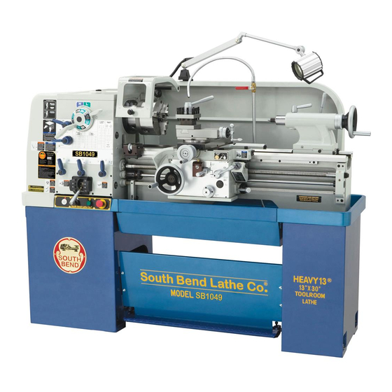
South bend SB1049 Manual (136 pages)
Heavy 13 - 13" x 40" Gearhead Lathe with Fagor DRO
Brand:
South bend
| Category:
Lathe
| Size: 14.27 MB
Table of Contents
Table of Contents
2
Introduction
9
About this Machine
9
Foreword
9
Capabilities
9
Features
9
General Identification
10
Controls & Components
11
Master Power Switch
11
Headstock
11
Control Panel
12
Carriage
12
Tailstock
13
End Gears
13
Safety Foot Brake
13
Product Dimensions
14
Weight
14
Shipping Dimensions
14
Type
14
Power Requirement
14
Full-Load Current Rating
14
Minimum Circuit Size
14
Plug Included
14
Recommended Plug Type
14
Product Specifications
14
Type
15
Horsepower
15
Phase
15
Amps
15
Safety
18
Understanding Risks of Machinery
18
Basic Machine Safety
18
Additional Metal Lathe Safety
20
Additional Chuck Safety
21
Preparation
22
Preparation Overview
22
Things You'll Need
22
Power Supply Requirements
23
Availability
23
Full-Load Current Rating
23
Circuit Requirements
23
Grounding Requirements
24
Extension Cords
24
Unpacking
25
Inventory
25
Cleaning & Protecting
26
Location
27
Physical Environment
27
Electrical Installation
27
Lighting
27
Weight Load
27
Space Allocation
27
Lifting & Moving
28
Leveling & Mounting
29
Leveling
29
Bolting to Concrete Floors
30
Assembly
30
Lubricating Lathe
30
Adding Coolant
31
Power Connection
31
Test Run
32
Speed
33
Spindle Break-In
36
Recommended Adjustments
36
Operation
37
Operation Overview
37
Chuck & Faceplate Mounting
38
Installation & Removal Devices
38
Chuck Installation
39
Registration Marks
40
Chuck Removal
40
Scroll Chuck Clamping
41
4-Jaw Chuck
41
Mounting Workpiece
41
Faceplate
42
Tailstock
43
Positioning Tailstock
43
Using Quill
43
Installing Tooling
44
Removing Tooling
45
Offsetting Tailstock
45
Aligning Tailstock to Spindle Centerline
46
Centers
47
Dead Centers
47
Live Centers
48
Mounting Dead Center in Spindle
48
Removing Center from Spindle
48
Mounting Center in Tailstock
48
Removing Center from Tailstock
49
Mounting Workpiece between Centers
49
Steady Rest
50
Follow Rest
51
Carriage & Slide Locks
51
Compound Rest
52
Four-Way Tool Post
52
Installing Tool
52
Aligning Cutting Tool with Spindle Centerline
53
Adjustable Feed Stop
54
Micrometer Stop
54
Manual Feed
55
Carriage Handwheel
55
Cross Slide Handwheel
55
Compound Rest Handwheel
55
Spindle Speed
55
Determining Spindle Speed
55
Setting Spindle Speed
56
Configuration Examples
56
Power Feed
57
Power Feed Controls
58
Setting Power Feed Rate
59
End Gears
60
Standard End Gear Configuration
60
Alternate Configuration
61
Threading
62
Headstock Threading Controls
62
Apron Threading Controls
63
Thread Dial
63
Thread Dial Chart
64
Chip Drawer
65
Coolant System
66
Accessories
67
Maintenance
70
Maintenance Schedule
70
Cleaning & Protecting
70
Maintenance Chart
71
Lubrication
72
Headstock
72
Quick-Change Gearbox
73
Apron
73
One-Shot Oiler
74
Longitudinal Leadscrew
74
Ball Oilers & Oil Cup
75
End Gears
76
Coolant System Service
77
Hazards
77
Adding Fluid
78
Changing Coolant
78
Machine Storage
79
Service
80
Backlash Adjustment
80
Compound Rest
80
Cross Slide
80
Leadscrew End Play Adjustment
81
Gib Adjustment
81
Half Nut Adjustment
83
V-Belts
83
Brake & Switch
84
Leadscrew Shear Pin Replacement
86
Gap Insert Removal & Installation
88
Gap Removal
88
Gap Installation
89
Troubleshooting
90
Electrical
93
Electrical Safety Instructions
93
Wiring Overview
94
Component Location Index
95
Electrical Cabinet Wiring
96
Electrical Box
97
Spindle Motor
98
Coolant Pump Motor Wiring
98
Control Panel Wiring
99
Spindle Switches
99
Additional Component Wiring
100
Power Connection
100
Parts
101
Headstock Cover
101
Headstock Controls
102
Headstock Internal Gears
104
Headstock Transfer Gears
106
Gearbox Gears
107
Gearbox Controls
109
Apron Front View
111
Apron Rear View
113
Compound Rest & Tool Post
115
Saddle Top View
116
Saddle Bottom View
118
Micrometer Stop
119
Dial Indicator
119
Bed & Shafts
120
End Gears
122
Main Motor
123
Stands & Panels
125
Tailstock
127
Steady Rest
129
Follow Rest
129
Electrical Cabinet & Control Panel
130
Accessories
131
Front Machine Labels
132
Rear & Side Machine Labels
133
Warranty
135
Advertisement
South bend SB1049 Owner's Manual (132 pages)
13" HEAVY 13 GEARHEAD LATHE
Brand:
South bend
| Category:
Lathe
| Size: 10.82 MB
Table of Contents
Table of Contents
3
Introduction
5
About this Machine
5
Foreword
5
Capabilities
5
Features
5
General Identification
6
Controls & Components
7
Master Power Switch
7
Headstock
7
Control Panel
8
Carriage
8
Tailstock
9
End Gears
9
Safety Foot Brake
9
Product Specifications
10
Safety
14
Understanding Risks of Machinery
14
Basic Machine Safety
14
Heavy
15
Additional Metal Lathe Safety
16
Additional Chuck Safety
17
Preparation
18
Preparation Overview
18
Things You'll Need
18
Power Supply Requirements
19
Availability
19
Full-Load Current Rating
19
Circuit Requirements
19
Grounding Requirements
20
Extension Cords
20
Unpacking
21
Inventory
21
Cleaning & Protecting
22
Location
23
Physical Environment
23
Electrical Installation
23
Lighting
23
Weight Load
23
Space Allocation
23
Lifting & Moving
24
Leveling & Mounting
25
Leveling
25
Bolting to Concrete Floors
26
Assembly
26
Lubricating Lathe
26
Adding Coolant
27
Power Connection
27
Test Run
28
Spindle Break-In
32
Recommended Adjustments
32
Operation
33
Operation Overview
33
Chuck & Faceplate Mounting
34
Installation & Removal Devices
34
Chuck Installation
35
Registration Marks
36
Chuck Removal
36
Scroll Chuck Clamping
37
4-Jaw Chuck
37
Mounting Workpiece
37
Faceplate
38
Tailstock
39
Positioning Tailstock
39
Using Quill
39
Installing Tooling
40
Removing Tooling
41
Offsetting Tailstock
41
Aligning Tailstock to Spindle Centerline
42
Centers
43
Dead Centers
43
Live Centers
44
Mounting Dead Center in Spindle
44
Removing Center from Spindle
44
Mounting Center in Tailstock
44
Removing Center from Tailstock
45
Mounting Workpiece between Centers
45
Steady Rest
46
Follow Rest
47
Carriage & Slide Locks
47
Compound Rest
48
Four-Way Tool Post
48
Installing Tool
48
Aligning Cutting Tool with Spindle Centerline
49
Adjustable Feed Stop
50
Micrometer Stop
50
Manual Feed
51
Carriage Handwheel
51
Cross Slide Handwheel
51
Compound Rest Handwheel
51
Spindle Speed
51
Determining Spindle Speed
51
Setting Spindle Speed
52
Configuration Examples
52
Power Feed
53
Power Feed Controls
54
Setting Power Feed Rate
55
End Gears
56
Standard End Gear Configuration
56
Alternate Configuration
57
Threading
58
Headstock Threading Controls
58
Apron Threading Controls
59
Thread Dial
59
Thread Dial Chart
60
Chip Drawer
61
Coolant System
62
Accessories
63
Maintenance
66
Maintenance Schedule
66
Cleaning & Protecting
66
Maintenance Chart
67
Lubrication
68
Headstock
68
Quick-Change Gearbox
69
Apron
69
One-Shot Oiler
70
Longitudinal Leadscrew
70
Ball Oilers & Oil Cup
71
End Gears
72
Coolant System Service
73
Hazards
73
Adding Fluid
74
Changing Coolant
74
Machine Storage
75
Service
76
Backlash Adjustment
76
Compound Rest
76
Cross Slide
76
Leadscrew End Play Adjustment
77
Gib Adjustment
77
Half Nut Adjustment
79
V-Belts
79
Brake & Switch
80
Leadscrew Shear Pin Replacement
82
Gap Insert Removal & Installation
84
Gap Removal
84
Gap Installation
85
Troubleshooting
86
Electrical
89
Electrical Safety Instructions
89
Wiring Overview
90
Component Location Index
91
Electrical Cabinet Wiring
92
Electrical Box
93
Spindle Motor
94
Coolant Pump Motor Wiring
94
Control Panel Wiring
95
Spindle Switches
95
Additional Component Wiring
96
Power Connection
96
Parts
97
Headstock Cover
97
Headstock Controls
98
Headstock Internal Gears
100
Headstock Transfer Gears
102
Gearbox Gears
103
Gearbox Controls
105
Apron Front View
107
Apron Rear View
109
Compound Rest & Tool Post
111
Saddle Top View
112
Saddle Bottom View
114
Micrometer Stop
115
Dial Indicator
115
Bed & Shafts
116
End Gears
118
Main Motor
119
Stands & Panels
121
Tailstock
123
Tailstock Parts List
124
Steady Rest
125
Follow Rest
125
Electrical Cabinet & Control Panel
126
Accessories
127
Front Machine Labels
128
Rear & Side Machine Labels
129
Warranty
131
Advertisement
Related Products
South bend SB1045PF
South bend TURN-NADO SB1042PF
South bend SB1043PF
South bend TURN-NADO SB1047F
South bend TURN-NADO SB1047PF
South bend TURN-NADO SB1048PF
South bend SB1049F
South bend SB1014
South bend TURN-NADO SB10146PF
South bend SB1050F
South bend Categories
Lathe
Saw
Power Tool
Dust Collector
Grinder
More South bend Manuals
Login
Sign In
OR
Sign in with Facebook
Sign in with Google
Upload manual
Upload from disk
Upload from URL