Sign In
Upload
Manuals
Brands
Skyjack Manuals
Lifting Systems
SJIII 4830
Skyjack SJIII 4830 Wheeled Scissor Lift Manuals
Manuals and User Guides for Skyjack SJIII 4830 Wheeled Scissor Lift. We have
1
Skyjack SJIII 4830 Wheeled Scissor Lift manual available for free PDF download: Operating & Maintenance Manual
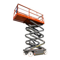
Skyjack SJIII 4830 Operating & Maintenance Manual (196 pages)
the conventionals
Brand:
Skyjack
| Category:
Lifting Systems
| Size: 6 MB
Table of Contents
Serial Number Breakdown
2
Table of Contents
3
Operator Safety Reminders
4
Base
7
Introduction
7
Description
7
Lifting Mechanism
7
Optional Accessories
7
Purpose of Equipment
7
Serial Number Nameplate
7
Use of Equipment
7
Warnings
7
Safety Rules
8
Optional Equipment (ANSI & CE)
10
Specifications and Features
10
Work Platform Major Component Identification
11
Electrical Panel
12
Emergency Battery Disconnect Switch
12
Operating Controls Identification
12
Operator Qualifications
12
Base Control Box (CE)
13
Base Controls-Hydraulic Emergency Lowering System
13
Base Controls-Hydraulic/Manual Parking Brake
14
Free-Wheeling Valve
14
Safety Bar and Pothole Protection Device
15
Operator’s Control Box
16
Platform Controls
16
Fold-Down Guardrail System
17
Powered Extension Platform Control Box
17
First Aid
18
Set-Up Procedure
18
Operating Procedures
19
Prestart Checks
19
Operator’s Checklist
19
Start and Operation
20
Shutdown Procedure
20
Battery Charging Procedures (Standard Machines)
21
Battery Service and Charging Procedures
21
Battery Charger Operation
22
Battery Charging Procedures (EE-Ratemachines)
22
Battery Status
22
MAC Charger
23
Section 3 Systems Component Identification and Schematics
24
System Component Identification and Schematics
24
Table of Contents
24
Control Box Diagram and Parts List with Horn (ANSI/SIA and CSA)
25
Control Box Diagram and Parts List with All Options (ANSI/SIA and CSA)
26
Control Box Diagram and Parts List with Horn (CE)
27
Control Box Diagram and Parts List with All Options (CE)
28
Electrical Symbol Chart
29
Relay Function Chart
30
Electrical Schematic Parts List with Horn (ANSI/SIA and CSA) Serial Numbers 608118, 66287, 703453, 86734, 75498 or 82263 & below
31
Electrical Schematic with Horn (ANSI/SIA and CSA) Serial Numbers 608118, 66287, 703453, 86734, 75498 or 82263 & below
32
Electrical Schematic with Horn (ANSI/SIA and CSA)
33
Electrical Schematic Parts List with Horn (ANSI/SIA and CSA)
34
Electrical Schematic with All Options (ANSI/SIA and CSA)
35
Electrical Schematic Parts List with All Options (ANSI/SIA and CSA)
36
Electrical Schematic Parts Listmodels 3220, 4620, 4626, 4830 & 4832 with All Options (CE)
37
Electrical Schematic Models 3220, 4620, 4626, 4830 & 4832 with All Options (CE)
38
Electrical Schematic Models 6826 and 6832 with All Options (CE)
39
Electrical Schematic Parts List Models 3220, 4620, 4626, 4830 & 4832 with All Options (CE)
40
Electrical Panel Parts List-No Options (ANSI/SIA and CSA) Serial Numbers 608118, 66287, 703453, 86734, 75498 or 82263 & below
41
Electrical Panel Diagram-No Options (ANSI/SIA and CSA) Serial Numbers 608118, 66287, 703453, 86734, 75498 or 82263 &Amp; below
42
Electrical Panel Diagram-No Options (ANSI/SIA and CSA)
43
Electrical Panel Parts List-No Options (ANSI/SIA and CSA)
44
Electrical Panel Parts List-All Options (ANSI/SIA and CSA) Serial Numbers 608118, 66287, 703453, 86734, 75498 or 82263 & below
45
Electrical Panel Diagram-All Options (ANSI/SIA and CSA) Serial Numbers 608118, 66287, 703453, 86734, 75498 or 82263 & below
46
Electrical Panel Diagram-All Options (ANSI/SIA and CSA)
47
Electrical Panel Parts List-All Options (ANSI/SIA and CSA)
48
Electrical Panel Parts List-All Options (Ce)Serial Numbers 608118, 66287, 703453, 86734, 75498 or 82263 & below
49
Electrical Panel Parts List-All Options (CE) Serial Numbers 608118, 66287, 703453, 86734, 75498 or 82263 & below
50
Electrical Panel Parts List-All Options (CE)
51
Battery Charger Schematic-Motor Appliance-Motor Appliance #BA610
53
Battery Charger Schematic Parts List-Bycan #2440A and 2440E
54
Hydraulic Symbol Chart
55
Hydraulic Schematic Parts List (Models 3220 & 4620)
56
Hydraulic Schematic (Models 3220 & 4620)
57
Hydraulic Schematic (Model 4626)
58
Hydraulic Schematic Parts List (Model 4626)
59
Hydraulic Schematic Parts List (Model 4830 & 4832)
60
Hydraulic Schematic (Model 4830 & 4832)
61
Hydraulic Schematic (Models 6826 & 6832)
62
Hydraulic Schematic Parts List (Models 6826 & 6832)
63
Hydraulic Manifold Component Identification
64
Electrical System
65
Troubleshooting Information
65
Hydraulic System
74
Maintenance and Service
76
Maintenance and Inspection Schedule
76
Owner's Annual Inspection Record
76
Hydraulic System and Component Maintenance and Repair
77
Maintenance and Inspection Schedule
78
Owner’s Annual Inspection Record
79
Maximum Platform Capacities (Evenly Distributed)
79
Torque Specifications
80
General Specifications-SJIII Series the Conventionals
81
Controller Troubleshooting Procedure
82
Proportional Controller
82
Controller Adjustment Procedure
83
Proportional Controller Adjustment
84
System and Lift Pressure Adjustments
85
General Maintenance Hints
76
Operator’s Responsibility for Maintenance
76
Hardware
86
How to Order Repair Parts
86
Parts Lists
86
Parts Ordering Information
86
Section 6 Parts Lists
86
List of Illustrations
87
Figure 6-1. Gate Options
89
FIGURE 6-2. MAIN PLATFORM and RAILINGS - Model 3220
91
FIGURE 6-3. MAIN PLATFORM and RAILINGS - Model 4620 with Rigid Railings
93
FIGURE 6-4. MAIN PLATFORM and RAILINGS - Model 4620 with Hinged Railings
95
FIGURE 6-5. MAIN PLATFORM and RAILINGS - Model 4626 with Hinged Railings
97
Main Platform and Railings-Model 4830 and 4832 with Hinged Railings
99
FIGURE 6-7. MAIN PLATFORM and RAILINGS - Model 6826 with Hinged Railings
101
FIGURE 6-8. MAIN PLATFORM and RAILINGS - Model 6832 with Hinged Railings
103
Figure 6-9. Ac Outlet on Platform Option
105
FIGURE 6-10. 3 FT. MANUAL EXTENSION PLATFORM - Models 3220, 4620, 4626,4830 and 4832
107
FIGURE 6-11. 3 FT. MANUAL EXTENSION PLATFORM - Models 6826 and 6832
109
Figure 6-12. Powered Extension Platform Assembly
111
FIGURE 6-13. HYDRAULIC HOSE CONNECTIONS - Powered Extension Platform
114
Figure 6-16. Operator's Control Box Assembly
118
Operator’s Control Box Assembly
118
Proportional Controller Assembly
121
Hose Connections-Scissors (Models 3220 and 4620)
122
Hose Connections-Scissors (Models 4626 and 6826)
123
FIGURE 6-20. HOSE CONNECTIONS - SCISSORS (Model 4830 and 4832)
124
FIGURE 6-21. HOSE CONNECTIONS - SCISSORS (Model 6832)
125
Scissor Arm Assembly-3220 and 4620
126
Scissor Arm Assembly-4626
128
Scissor Arm Assembly-4626 and 6826
129
Scissor Arm Assembly-4830 and 4832
130
Scissor Arm Assembly-6832
132
Figure 6-26. Lift Cylinder Assembly
134
FIGURE 6-27. BASE, AXLES and WHEELS - Models 3220, 4620, 4626, 4830 and 4832
136
FIGURE 6-28. BASE, AXLES and WHEELS - Models 6826 and 6832
140
Figure 6-29. Pot Hole Protection Device
143
FIGURE 6-30. HYDRAULIC HOSE CONNECTIONS - Base (Models 3220, 4620, 4626, 4830 and 4832)
145
FIGURE 6-31. HYDRAULIC HOSE CONNECTIONS - Base (Models 6826 and 6832)
147
Brake Cylinder Assembly
149
Steer Cylinder Assembly
150
Rear Drive Manifold Assembly-Models 3220, 4620, 4626, 4830 and 4832
151
Rear Drive Manifold Assembly-Models 6826 and 6832
152
Figure 6-36. Base Control Box Option (Ce)
153
Figure 6-37. Hydraulic/Electric Tray Assembly
155
FIGURE 6-38. HYDRAULIC HOSE CONNECTIONS - Hydraulic/Electric Tray
158
FIGURE 6-39. BATTERY TRAY ASSEMBLY (Models 3220, 4620, 4626,4830 and 4832)
160
FIGURE 6-40. BATTERY TRAY ASSEMBLY (Models 6826 and 6832)
162
Battery Charger Assembly (Motor Appliance Model BA610)
164
Battery Charger Assembly (Motor Appliance Model BA169)
165
Battery Charger Assembly (Motor Appliance Model BA1044)
166
Battery Charger Assembly (Bycan Model 2440A and 2440E)
167
Battery Charger Assembly (Bycan Model 2440U)
168
Proportional Control Manifold Assembly
169
Powered Extension Platform Cylinder Assembly
116
Powered Extension Platform Control Box Assembly
117
Figure 6-47. Main Manifold Assembly
170
FIGURE 6-48. ELECTRICAL PANEL ASSEMBLY (ANSI/SIA and CSA)
172
Electrical Panel Assembly (EE-Rated) (ANSI/SIA and CSA)
174
Figure 6-50. Electrical Panel Assembly (Ce)
176
Labels and Nameplates-ANSI/SIA and CSA
178
Figure 6-52. Labels and Nameplates (Ce)
180
Air Hose to Platform Option
182
Figure 6-54. 800 Watt Generator Option
183
FIGURE 6-55. SCISSOR GUARD OPTION (Models 6826 and 6832)
184
Scissor Guard Option (French)
187
Scissor Guard Option (Galvenized Mesh)
189
Figure 6-58. Light Duty Pipe Rack Option
192
Advertisement
Advertisement
Related Products
Skyjack SJIII 3226
Skyjack SJIII 4632
Skyjack SJIII 3220
Skyjack SJIII 3220m
Skyjack SJIII 4620
Skyjack SJIII 4626
Skyjack SJIII 6832
Skyjack SJIII 4832
Skyjack SJIII 4740
Skyjack SJ45 T+
Skyjack Categories
Boom Lifts
Lifting Systems
Scissor Lifts
Forklifts
Safety Equipment
More Skyjack Manuals
Login
Sign In
OR
Sign in with Facebook
Sign in with Google
Upload manual
Upload from disk
Upload from URL