Sign In
Upload
Manuals
Brands
Skyjack Manuals
Lifting Systems
SJ45 T+
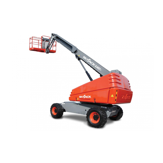
User Manuals: Skyjack SJ45 T+ Telescopic Boom Lift
Manuals and User Guides for Skyjack SJ45 T+ Telescopic Boom Lift. We have
3
Skyjack SJ45 T+ Telescopic Boom Lift manuals available for free PDF download: Service Manual, Operation Manual
Skyjack SJ45 T+ Service Manual (154 pages)
TELESCOPIC BOOMS
Brand:
Skyjack
| Category:
Boom Lifts
| Size: 17 MB
Table of Contents
Table of Contents
5
Section 1 - Scheduled Maintenance
11
Read and Heed
11
Mobile Elevating Work Platform (MEWP) Definition
11
Purpose of Equipment
11
Use of Equipment
11
Manual
11
Service Policy and Warranty
11
Operator Safety Reminders, Warnings and Precautions
11
Maintenance and Service
12
Maintenance and Inspection Schedule
12
Owner's Annual Inspection Record
12
Replacement Parts
12
Maintenance and Service Safety Tips
12
Hydraulic System & Component Maintenance and Repair
13
Hydraulic Maintenance Hints
13
Railing Maintenance and Repair
14
Scheduled Maintenance
15
Service Bulletins
15
Maintenance and Inspection
15
Maintenance Instructions
15
Owner's Annual Inspection Record
16
Pre-Delivery/Maintenance Inspection Checklist
17
Scheduled Maintenance Inspections
18
Electrical
18
Hydraulic
18
Labels (B)
18
Limit Switches (B)
18
Engine Compartment
19
Control Compartment
22
Base
24
Platform
26
Boom Assembly (B)
27
10 Optional Equipment (B)
28
Function Tests
29
Section 2 - Maintenance Tables and Diagrams
30
Standard Hose Numbering System
30
MEWP Torque Specifications
32
Axle Torque Specifications
33
Torque Specifications for Fasteners (US)
34
Torque Specifications for Fasteners (Metric)
35
Torque Specifications for Hydraulic Couplings & Hoses
36
Axles Maintenance Intervals
37
Tires
38
Floor Loading Pressure
39
Hydraulic Specifications
40
Fluids
41
Engine
41
MEWP Specifications
42
Maximum Platform Capacities
43
Reach Diagram - SJ40 T
44
Reach Diagram - SJ45 T
44
Dimension Diagrams - SJ40 T
45
Dimension Diagrams - SJ45 T
46
Axle Oscillation Diagrams
47
Section 3 - System Component Identification and Schematics
48
Electrical Symbol Chart
49
Hydraulic Symbol Chart
50
Wire Number and Color Code
51
Hydraulic Parts List
52
Electrical Component Parts List
55
Rotary Manifold Port Identification
58
Brake Manifold Port Identification
59
System Pump Port Identification
60
Drive Pump Port Identification
61
Drive Motor Port Identification
62
Jib Valve Port Identification - SJ45 T
63
No Jib Valve Port Identifications - SJ40 T
64
Main Manifold Port Identification
65
Main Manifold Electrical Component Identification
66
Main Manifold Hydraulic Component Identification
67
Main Harness Wiring Diagram
68
Engine Harness
69
Engine Harness Schematic
70
Platform Harnesses
71
Limit Switch Connections
72
Flashing Light Connection
73
Differential Lock Harness
74
Hydraulic Schematic
75
Platform Controls Wiring - SJ40 T
76
Platform Controls Wiring - SJ45 T
77
Base Controls Wiring - SJ40 T
78
Base Controls Wiring - SJ45 T+ ANSI/CSA & as
79
Base Controls Wiring - SJ45 T+ CE
80
Electrical Schematic - ANSI/CSA & as
81
Electrical Schematic - CE
82
Engine Schematic - Kubota D1305
83
Engine Schematic - Kuboa WG972
84
Section 4 - Troubleshooting Information
85
Introduction
85
Electrical System
86
All Controls Are Inoperative from the Base or Platform Console
86
All Controls Are Inoperative from the Base Console
88
The Engine will Not Crank from the Base or Platform
88
The Engine will Not Crank from the Base
89
The Engine will Not Crank from the Platform
89
The Boom Controls Are Inoperative (Drive Operates)
89
No Boom up from the Base or Platform Controls
90
No Boom up from the Base Console
90
No Boom up from the Platform Console
90
10 No Boom down from the Base or Platform Consoles
90
11 No Boom down from the Base Console
91
12 No Boom down from the Platform Console
91
13 No Turret Rotate Right from the Base or Platform Consoles
91
14 No Turret Rotate Right from the Platform Console
91
15 No Turret Rotate Right from the Platform Console
92
16 No Turret Rotate Left from the Base or Platform Consoles
92
17 No Turret Rotate Left from the Base Console
92
18 No Turret Rotate Left from the Platform Console
92
19 No Telescope out from the Base or Platform Consoles
93
20 No Telescope out from the Base Console
93
21 No Telescope out from the Platform Console
93
22 No Telescope in from the Base or Platform Consoles
94
23 No Telescope in from the Base Console
94
24 No Telescope in from the Platform Console
94
25 No Platform Level up from the Base or Platform Consoles
94
26 No Platform Level up from the Base Console
95
27 No Platform Level up from the Platform Console
95
28 No Platform Level down from the Base or Platform Consoles
95
29 No Platform Level down from the Base Console
95
30 No Platform Level down from the Platform Console
96
31 No Platform Rotate or Jib Functions from the Base or Platform Consoles
96
32 No Platform Rotate Right from the Base or Platform Consoles
96
33 No Platform Rotate Right from the Base Console
97
34 No Platform Rotate Right from the Platform Console
97
35 No Platform Rotate Left from the Base or Platform Consoles
97
36 No Platform Rotate Left from the Base Console
97
37 No Platform Rotate Left from the Platform Console
98
38 No Jib up from the Base or Platform Consoles
98
39 No Jib up from the Base Console
98
40 No Jib up from the Platform Console
98
41 No Jib down from the Base or Platform Consoles
99
42 No Jib down from the Base Console
99
43 No Jib down from the Platform Console
99
44 No Drive or Steer Functions
99
45 No Forward or Reverse Drive
100
46 No Forward Drive
100
47 No Reverse Drive
100
48 The Brake will Not Release
101
49 No Left Steer
101
50 No Right Steer
102
51 The Directon Sensing Is Inoperative
102
53 The Overload Indicator Light Does Not Turn on When the Platform Is Overloaded
103
54 The Audible Alarm Does Not Turn on with the Platform Overloaded
103
Hydraulic System
104
All Controls Are Inoperative
104
All Boom Functions Are Inoperative
104
No Main Boom up
104
No Main Boom down
105
No Turret Rotate
105
No Boom Extend
106
No Boom Retract
107
No Jib up
107
No Jib down
108
10 No Platform Rotation
108
11 Platform will Not Level
109
12 Brake will Not Release
110
13 Brake will Not Engage
110
14 No Drive
110
15 Differential Lock will Not Engage
111
16 No High Speed Drive
111
17 No Steer
111
18 Axle will Not Oscillate
112
19 Axle will Not Lock
112
Section 5 - Procedures
113
General
113
Safety and Workmanship
113
Platform
114
Human Machine Interface (HMI)
114
User Interface Keys
114
OCM Character Functions Charts
115
OCM Pin Reference
116
SCM Calibration
122
SCM Calibration Flowchart
123
Platform Controller Voltage References
125
Boom
126
Check Wear Pads
126
Shim Wear Pads
126
Cable Carrier Repair
126
Rotary Actuator Bolt Torque Procedure
126
Limit Switch Locations
127
Turret
128
Check and Replace the High Pressure Filter
128
Adjust the Turret Rotation Gear Backlash
128
Check the Swing Drive Oil
129
Change the Swing Drive Oil
129
Battery Replacement
130
Turret Rotation Gear Bolt Torque Sequence
130
Electronic Tilt Switch Setup Procedure
131
Check Rotation Bearing for Axial Wear
133
Engines
134
Replace the Engine Oil and Filter
134
Replace the Fuel Filter
134
Replace the Air Filter
134
Check the Engine Belt
135
Hydraulic Tank
136
Hydraulic Oil Replacement
136
Hydraulic Filter Replacement
136
Manifold and Hydraulic Pumps
137
Hydraulic Brake Pressure Adjustment
137
Hydraulic Standby Pressure Adjustment
138
Hydraulic High Pressure Adjustment
139
Hydraulic System Relief Valve Adjustment
140
Turret Rotate Relief Valve Adjustment
141
Platform Level Relief Valve Adjustment
141
Fly Boom Relief Valve Adjustment
142
Test Charge Pump Pressure on Drive Pump
142
Test Forward Drive Pressure on Drive Pump
143
10 Test Reverse Drive Pressure on Drive Pump
143
Axles
144
Change the Oil in the Axles
144
Check the Oil Level in the Torque Hubs
144
Change the Oil in the Torque Hubs
144
Check the Oil Level in the Axle Gearbox
145
Change the Oil in the Axle Gearbox
145
Oscillating Cylinder Bolt Replacement
146
Oscillating Cylinder Replacement
146
Bleed the Oscillating Axle Cylinders
148
Test the Oscillating Axle Cylinders
148
10 Pin Brake Adjustments
149
11 Brake Inspection
150
Grease Points
151
Grease the Turret Ring Gear
151
Grease the Turret Swing Drive
151
Grease the Axles
152
Grease the Drive Shaft
152
Advertisement
Skyjack SJ45 T+ Operation Manual (130 pages)
TELESCOPIC BOOMS
Brand:
Skyjack
| Category:
Lifting Systems
| Size: 8 MB
Table of Contents
Table of Contents
5
Section 1 - about this Mobile Elevating Work Platform (MEWP)
11
Read and Heed
11
Mobile Elevating Work Platform (MEWP) Definition
11
Purpose of Equipment
11
Use of Equipment
11
Operation Manual
11
Operator
11
Service Policy and Warranty
11
Ownership of MEWP
11
Optional Equipment
11
Scope of this Manual
12
Primary Assemblies
13
Serial Number Nameplate
15
Maintenance Responsibility
16
Operator
16
Maintenance and Inspection Schedule
16
Owner
16
Section 2 - General Safety Precautions
17
Electrocution Hazards
17
Minimum Distance from Electrical Conductors
17
Safety Instructions
18
Fall-Protection
21
Worksite Inspection
21
Section 3 - Familiarization
23
Overview of the MEWP
24
Manual Storage Box
25
Control Functions
25
Main Power Disconnect Switch
25
Footswitch
25
Base Control Console
26
Platform Control Console
28
Features and Devices
31
Lowered Travel Position and Elevated Travel Position
31
Drive Speed
32
Drive Direction
32
Tilt Switch
32
Function Restrictions When the MEWP Is Tilted
32
Platform Load Sensing System
32
Overload Status
33
Brake-Release System
34
Secondary Guarding Electrical (SGE)
34
10 Drive-Bypass Valve
35
11 AC Power Socket on the Platform
35
12 Motion Alarm
35
13 Differential Lock Switch
35
14 Turret Transportation Lock
35
Optional Equipment and Attachments
36
AC Power Socket on the Platform
36
Flashing Amber Light
36
Welder
36
Cold or Arctic Weather Package
37
Tool Tray
37
Glazier
37
Pipe Rack
38
Elevate™ Telematics - Access Control Unit
38
Section 4 - Inspections before Operation
41
Operator's Responsibility
41
Visual and Daily Maintenance Inspections
42
Labels
42
Electrical
42
Limit Switches
42
Hydraulic
42
Engine Compartment
43
Control Compartment
45
Base
46
Platform Assembly
48
Boom Assembly
49
10 Optional Equipment
50
Function Tests
51
Do a Test of the Main Power Disconnect Switch
51
Do a Test of the Base Keyswitch and the Emergency-Stop Button and Light
51
Functions
52
Do a Test of the Platform Self-Leveling
52
Do a Test of the Platform Capacity Zone Indicator Lights
53
Do a Test of the Emergency Power Unit
53
Do a Test of the Off/Base/Platform Switch
54
Do a Test of the Positive Air Shut-Off Switch (Optional Equipment)
54
Do a Test of the Emergency-Stop Button and Emergency-Stop Light on the Platform
55
10 Do a Test of the Load Sensing Module Self-Check
55
11 Do a Test of the Footswitch and All the Boom and Platform Functions
56
12 Do a Test of the Platform Capacity Zone Indicator Lights
56
13 Do a Test of the Secondary Guarding Electrical (SGE)
57
14 Do a Test of the Engine Start/On/Off Switch
58
15 Do a Test of the Emergency Power Unit
58
16 Do a Test of the Manual Platform-Leveling
59
17 Do a Test of the Steer Function
59
18 Do a Test of the Drive Function
59
19 Do a Test of the Brakes
59
20 Do a Test of the Horn
59
21 Do a Test of the Elevated Travel Speed
60
22 Do a Test of the Differential Lock Switch
60
23 Do a Test of the Oscillating Cylinders
61
24 Do a Test of the Wire Ropes (SJ61 T+/SJ66 T+ Only)
61
Operator's Checklist
62
Section 5 - Operation
65
Energize the Base Control Console
65
Rotate the Platform with the Base Control Console
66
Rotate the Turret with the Base Control Console
66
Move the Jib up and down with the Base Control Console
66
Raise or Lower the Main Boom with the Base Control Console
66
Extend or Retract the Boom with the Base Control Console
66
Make the Platform Level with the Base Control Console
67
Operate with the Emergency Power Switch at the Base Control Console
67
Energize the Platform Control Console
67
Drive Forward or Rearward
68
Steer
68
Move the Jib up and down with the Platform Control Console
68
Extend or Retract the Boom with the Platform Control Console
68
Make the Platform Level with the Platform Control Console
68
Rotate the Platform with the Platform Control Console
68
Raise or Lower the Main Boom with the Platform Control Console
69
Operate the Horn
69
Rotate the Turret with the Platform Control Console
69
Operate with the Emergency Power Switch at the Platform Control Console
69
Engage or Disengage the Differential Lock Switch
69
MEWP Shutdown
70
Generator (Optional Equipment)
70
Glazier Tray (Optional Equipment)
70
Pipe Rack (Optional Equipment)
70
Arctic Weather Package (Optional Equipment)
71
Section 6 - Additional Procedures
73
Use the Emergency-Lowering Function
73
At the Base Control Console
73
At the Platform Control Console
73
Chassis Tilt Recovery
74
Platform Uphill
74
Platform Downhill
74
Release the Brakes Manually
75
Winch and Tow the MEWP
76
Refuel
77
Refuel the MEWP with Diesel or Gasoline
77
Replace the Propane Cylinder (Optional Equipment)
78
Move the MEWP for Transport
79
Lock the Turret
79
Hoist the MEWP
80
Tie down the MEWP
82
Section 7 - Technical Diagrams and Specifications
83
Technical Diagrams
84
Reach Diagram - SJ40 T
84
Reach Diagram - SJ45 T
84
Reach Diagram - SJ61 T
85
Reach Diagram - SJ66 T
85
Dimensions - SJ40 T
86
Dimensions - SJ45 T
88
Dimensions - SJ61 T
90
Dimensions - SJ66 T
92
Standard and Optional Equipment
94
Owner's Annual Inspection Record
95
Specifications
96
Environment
98
Tire/Wheel Specifications
98
Maximum Platform Capacities (Evenly Distributed)
99
Floor Loading Pressure
100
Section 8 - Labels
101
SJ40 T+/SJ45 T+ & SJ61 T+/SJ66 T+ Labels
102
Engine Side
102
Front Side
107
Control Side
108
Platform
113
Control Compartment
115
Rear Side
119
Platform Control Console
122
Section 9 - Unique Skyjack Features
127
Skyjack SJ45 T+ Operation Manual (116 pages)
TELESCOPIC BOOMS
Brand:
Skyjack
| Category:
Boom Lifts
| Size: 9 MB
Table of Contents
Table of Contents
5
Section 1 - about this Mobile Elevating Work Platform (MEWP)
9
Read and Heed
9
Mobile Elevating Work Platform (MEWP) Definition
9
Purpose of Equipment
9
Use of Equipment
9
Operation Manual
9
Operator
9
Service Policy and Warranty
9
Ownership of MEWP
9
Optional Equipment
9
Scope of this Manual
10
Primary Assemblies
11
Serial Number Nameplate
12
Maintenance Responsibility
13
Operator
13
Maintenance and Inspection Schedule
13
Owner
13
Section 2 - General Safety Precautions
14
Electrocution Hazards
14
Minimum Distance from Electrical Conductors
14
Safety Instructions
15
Fall-Protection
18
Worksite Inspection
18
Section 3 - Familiarization
19
Overview of the MEWP
20
Manual Storage Box
21
Control Functions
21
Main Power Disconnect Switch
21
Footswitch
21
Engine Display Module
21
Positive Air Shut-Off (Optional Equipment)
21
Base Control Console
22
Platform Control Console
24
Features and Devices
27
Lowered Travel Position and Elevated Travel Position
27
Drive Speed
28
Drive Direction
28
Tilt Switch
28
Function Restrictions When the MEWP Is Tilted
28
Platform Load Sensing System
28
Overload Status
29
Brake-Release System
30
Secondary Guarding Electrical (SGE)
30
10 Drive-Bypass Valve
31
11 AC Power Socket on the Platform
31
12 Motion Alarm
31
13 Differential Lock Switch
31
14 Turret Transportation Lock
31
Optional Equipment
32
AC Power Socket on the Platform
32
Flashing Amber Light
32
Welder
32
Cold or Arctic Weather Package
33
Tool Tray
33
Glazier
33
Pipe Rack
34
Elevate™ Telematics - Access Control Unit
34
Section 4 - Inspections before Operation
36
Operator's Responsibility
36
Visual and Daily Maintenance Inspections
37
Labels
37
Electrical
37
Limit Switches
37
Hydraulic
37
Engine Compartment
38
Control Compartment
40
Base
42
Platform Assembly
44
Boom Assembly
45
10 Optional Equipment
46
Function Tests
47
Do a Test of the Main Power Disconnect Switch
47
Do a Test of the Base Keyswitch and the Emergency-Stop Button and Light
47
Functions
48
Do a Test of the Platform Self-Leveling
48
Do a Test of the Platform Capacity Zone Indicator Lights
49
Do a Test of the Emergency Power Unit
49
Do a Test of the Off/Base/Platform Switch
50
Do a Test of the Positive Air Shut-Off Switch (Optional Equipment)
51
Do a Test of the Emergency-Stop Button and Emergency-Stop Light on the Platform
52
10 Do a Test of the Load Sensing Module Self-Check
52
11 Do a Test of the Footswitch and All the Boom and Platform Functions
53
12 Do a Test of the Platform Capacity Zone Indicator Lights
53
13 Do a Test of the Secondary Guarding Electrical (SGE)
54
14 Do a Test of the Engine Start/On/Off Switch
55
15 Do a Test of the Emergency Power Unit
55
16 Do a Test of the Manual Platform-Leveling
56
17 Do a Test of the Steer Function
56
18 Do a Test of the Drive Function
56
19 Do a Test of the Brakes
56
20 Do a Test of the Horn
56
21 Do a Test of the Elevated Travel Speed
57
22 Do a Test of the Differential Lock Switch
57
23 Do a Test of the Oscillating Cylinders
58
Operator's Checklist
60
Section 5 - Operation
61
Energize the Base Control Console
61
Rotate the Platform with the Base Control Console
62
Rotate the Turret with the Base Control Console
62
Move the Jib up and down with the Base Control Console
62
Raise or Lower the Main Boom with the Base Control Console
62
Extend or Retract the Boom with the Base Control Console
62
Make the Platform Level with the Base Control Console
63
Operate with the Emergency Power Switch at the Base Control Console
63
Energize the Platform Control Console
63
Drive Forward or Rearward
64
Steer
64
Move the Jib up and down with the Platform Control Console
64
Extend or Retract the Boom with the Platform Control Console
64
Make the Platform Level with the Platform Control Console
64
Rotate the Platform with the Platform Control Console
64
Raise or Lower the Main Boom with the Platform Control Console
65
Operate the Horn
65
Rotate the Turret with the Platform Control Console
65
Operate with the Emergency Power Switch at the Platform Control Console
65
Engage or Disengage the Differential Lock Switch
65
MEWP Shutdown
66
Generator (Optional Equipment)
66
Glazier Tray (Optional Equipment)
66
Pipe Rack (Optional Equipment)
66
Cold or Arctic Weather Package (Optional Equipment)
67
Section 6 - Additional Procedures
68
Use the Emergency-Lowering Function
68
At the Base Control Console
68
At the Platform Control Console
68
Chassis Tilt Recovery
69
Platform Uphill
69
Platform Downhill
69
Release the Brakes Manually
70
Winch and Tow the MEWP
71
Refuel
72
Refuel the MEWP with Diesel
72
Move the MEWP for Transport
73
Lock the Turret
73
Hoist the MEWP
74
Tie down the MEWP
75
Section 7 - Technical Diagrams and Specifications
76
Technical Diagrams
77
Reach Diagram - SJ40 T
77
Reach Diagram - SJ45 T
77
Dimensions - SJ40 T
78
Dimensions - SJ45 T
80
Standard and Optional Equipment
82
Owner's Annual Inspection Record
83
Specifications
84
Environment
85
Tire/Wheel Specifications
85
Maximum Platform Capacities (Evenly Distributed)
86
Floor Loading Pressure
87
Section 8 - Labels
88
Engine Side
89
Engine Compartment
92
Front
94
Control Side
95
Control Compartment
100
Rear
104
Platform
107
Platform Railings
109
Platform Control Console
110
Section 9 - Unique Skyjack Features
113
Advertisement
Advertisement
Related Products
Skyjack SJ4732
Skyjack SJ4740
Skyjack SJ4726
Skyjack Telescopic Boom SJ 40T
Skyjack SJ46 AJ
Skyjack SJ40 T+
Skyjack SJ16
Skyjack SJIII 4620
Skyjack SJIII 4832
Skyjack SJIII 4740
Skyjack Categories
Boom Lifts
Lifting Systems
Scissor Lifts
Forklifts
Safety Equipment
More Skyjack Manuals
Login
Sign In
OR
Sign in with Facebook
Sign in with Google
Upload manual
Upload from disk
Upload from URL