User Manuals: SIGLENT SNA5000A Vector Network Analyzer
Manuals and User Guides for SIGLENT SNA5000A Vector Network Analyzer. We have 4 SIGLENT SNA5000A Vector Network Analyzer manuals available for free PDF download: User Manual, Quick Start Manual
SIGLENT SNA5000A User Manual (329 pages)
Digital Oscilloscope
Brand: SIGLENT
|
Category: Test Equipment
|
Size: 17 MB
Table of Contents
-
Introduction13
-
Cleaning21
-
Nettoyage29
-
First Steps31
-
Power on33
-
Shut down33
-
Quick Start34
-
Power Supply38
-
Probes38
-
Lan39
-
Logic Probe41
-
Web Browser42
-
Overview44
-
Menu Bar45
-
Grid Area45
-
Dialog Box51
-
Front Panel57
-
Overview57
-
Menu Bar62
-
Overview71
-
Overview77
-
Acquisition78
-
Roll Mode82
-
Sequence82
-
History85
-
Zoom88
-
Trigger91
-
Overview91
-
Trigger Mode94
-
Trigger Type95
-
Overview95
-
Edge Trigger96
-
Window Trigger103
-
Interval Trigger104
-
Dropout Trigger105
-
Runt Trigger106
-
Pattern Trigger106
-
Nth Edge Trigger109
-
Delay Trigger109
-
Serial Trigger110
-
Trigger Source111
-
Holdoff112
-
Trigger Coupling113
-
Noise Reject114
-
Zone Trigger115
-
Overview119
-
I2C Trigger122
-
Spi Trigger130
-
Uart Trigger132
-
Can Trigger134
-
Lin Trigger136
-
Flexray Trigger139
-
Can Fd Trigger141
-
I2S Trigger145
-
Sent Trigger151
-
Cursors164
-
Overview164
-
Measurement172
-
Overview172
-
Set Parameters173
-
Trend181
-
Track182
-
Display Mode183
-
Gate187
-
Threshold188
-
Math189
-
Overview189
-
Arithmetic190
-
Average / Eres192
-
Algebra192
-
Differential192
-
Integral193
-
Square Root194
-
Absolute194
-
Sign195
-
Exp/Exp10195
-
Ln/Lg196
-
Interpolate196
-
Filter197
-
Formula Editor207
-
Memory209
-
Analysis Gate212
-
Overview212
-
Gate Setup214
-
Search215
-
Navigate218
-
Signalscan224
-
Overview224
-
Scan Mode225
-
Scan Tools226
-
List226
-
Scan Zoom227
-
Histogram228
-
Overlay229
-
Trigger Action230
-
Mask Test231
-
Overview231
-
Mask Setup233
-
Create Mask233
-
Mask Editor234
-
Pass/Fail Rule236
-
Operation236
-
DVM237
-
Overview237
-
Mode238
-
Diagrams239
-
Counter242
-
Overview242
-
Mode243
-
Histogram245
-
Overview245
-
Region Setting247
-
Power Analysis249
-
Overview249
-
Power Quality249
-
Inrush Current254
-
Switching Loss255
-
Slew Rate258
-
Modulation259
-
Output Ripple259
-
Turn On/Turn off260
-
Psrr263
-
Power Efficiency264
-
Soa264
-
Bode Plot267
-
Overview267
-
Configuration268
-
Connection268
-
Sweep268
-
Display270
-
Data Analysis272
-
Eye Diagram276
-
Overview276
-
Signal Setting278
-
Clock Recovery278
-
Measurement280
-
Mask Test281
-
Other Operation281
-
Jitter Analysis283
-
Overview283
-
Clock Recovery285
-
Jitter Measure286
-
Other Operation289
-
Compliance Test290
-
Overview291
-
Wave Type292
-
Other Setting293
-
System294
-
Display296
-
Display Type297
-
Color Grade298
-
Set Persist299
-
Set Grid300
-
Color Setting301
-
Save/Recall306
-
Save Type306
-
File Manager308
-
Utility312
-
System Setting312
-
Language312
-
Screen Saver313
-
Sound313
-
Date/Time313
-
Touch Screen316
-
I/O Setting317
-
Lan317
-
Clock Source317
-
Install Options318
-
Maintenance319
-
Upgrade319
-
Self-Calibration320
-
Self Test321
-
Service324
-
Smb File Share324
-
Web325
-
Emulation325
-
Save Button326
-
Quick Action326
-
Troubleshooting327
Advertisement
SIGLENT SNA5000A User Manual (295 pages)
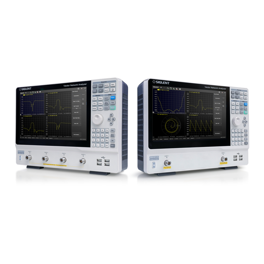
Vector Network Analyzer
Brand: SIGLENT
|
Category: Measuring Instruments
|
Size: 11 MB
Table of Contents
-
Content3
-
Copyright12
-
Calibration16
-
Cleaning16
-
Features17
-
Quick Start21
-
Dimensions21
-
Power Supply22
-
Front Panel23
-
Power Switch25
-
Rear Panel27
-
Active Entry31
-
Trace State31
-
Hardkeys32
-
Label Page32
-
Window State33
-
Status Bar33
-
Message Bar33
-
Touch Screen40
-
S Parameters43
-
Ratio54
-
Power Level56
-
Sweep58
-
Points58
-
Sweep Type59
-
Trigger62
-
Trigger Mode64
-
Data Format69
-
Scale74
-
Divisions78
-
Scale Type79
-
Avg BW79
-
Overview79
-
Averaging80
-
IF Bandwidth80
-
Smoothing82
-
Overview85
-
Basic Cal93
-
Overview103
-
Connector Tab104
-
Standards Tab106
-
SOLT Tab108
-
TRL Tab109
-
Power Cal116
-
Port Extension118
-
Port Match122
-
2-Port De-Embed124
-
Adapter Removal128
-
Ecal129
-
Ecal Overview129
-
Ecal Config130
-
Confidence Check131
-
Orientation132
-
Characterization133
-
Data Analysis135
-
Marker135
-
Ordinary Marker135
-
Reference Marker135
-
Marker Setting135
-
Marker Display138
-
Marker Function138
-
Search Domain139
-
Peak Search140
-
Target Search141
-
Tracking Search142
-
Bandwidth Search143
-
Notch Search143
-
Conversion145
-
Equation Editor147
-
Trace Statistics156
-
Limit Test156
-
Point Limit Test159
-
Time Domain164
-
Transform164
-
Gating166
-
Window168
-
Coupling170
-
Marker171
-
Advance172
-
Save and Recall174
-
Overview177
-
TDR Setup Wizard179
-
Deskew180
-
DUT Topology183
-
DUT Length183
-
Port Impedance184
-
Power Level185
-
Average185
-
IF Bandwidth186
-
Trigger Mode186
-
TDR Trace Setup186
-
Select a Trace186
-
Scale Management187
-
Smoothing190
-
Trace Allocation190
-
DC Value192
-
Marker Setup193
-
Rise Time Search193
-
Peeling194
-
Overview195
-
View Point201
-
Embedding202
-
Equalization203
-
Hot TDR205
-
Overview205
-
Usage Guidelines206
-
Overview208
-
User Interface208
-
SA Setting Tab211
-
Source Tab215
-
Advanced Tab217
-
Trace Setup219
-
Marker → SA221
-
Channel Power222
-
Acpr224
-
Occupied BW226
-
Toi227
-
Cnr229
-
Spectrum Monitor231
-
Overview233
-
Overview249
-
Overview252
-
Pulse Timing253
-
Properties254
-
Overview257
-
Preset Tab259
-
Overview272
-
System Setting279
-
Firmware Upgrade280
-
File Browser280
-
Screensaver281
-
System Language281
-
Power281
-
LAN Status282
-
Mdns Setting282
-
Lxi282
-
VNC Setting282
-
Web Setting282
-
Gpib283
-
External Device283
-
Preset283
-
Factory Reset284
-
Help Information285
-
Help and about285
-
Message Setting285
-
View Message285
-
Buzzer285
-
Self-Test286
-
Performance Test286
-
Options291
-
External Ports291
-
Contact SIGLENT293
SIGLENT SNA5000A User Manual (243 pages)
Vector Network Analyzer
Brand: SIGLENT
|
Category: Measuring Instruments
|
Size: 8 MB
Table of Contents
-
Content3
-
Calibration13
-
Cleaning13
-
Features14
-
Quick Start18
-
Dimensions18
-
Power Supply19
-
Front Panel20
-
Power Switch24
-
Rear Panel25
-
Active Entry29
-
Trace State29
-
Hardkeys30
-
Label Page31
-
Window State32
-
Status Bar32
-
Message Bar33
-
Touch Screen36
-
S Parameters37
-
Power Level49
-
Sweep52
-
Points52
-
Sweep Type53
-
Trigger56
-
Trigger Mode58
-
Data Format63
-
Scale68
-
Divisions72
-
Scale Type72
-
Avg BW73
-
Overview73
-
Averaging73
-
IF Bandwidth74
-
Smoothing75
-
Overview78
-
Port Extension110
-
Ecal121
-
Ecal Overview121
-
Ecal Config122
-
Confidence Check123
-
Orientation124
-
Characterization125
-
Data Analysis126
-
Marker126
-
Ordinary Marker126
-
Reference Marker126
-
Marker Setting126
-
Marker Function129
-
Conversion137
-
Equation Editor139
-
Trace Statistics148
-
Limit Test148
-
Time Domain154
-
Transform154
-
Gating156
-
Window157
-
Coupling159
-
Marker160
-
Overview162
-
TDR Setup Wizard164
-
Deskew165
-
DUT Topology167
-
DUT Length167
-
Port Impedance169
-
Power Level169
-
Average169
-
IF Bandwidth170
-
Trigger Mode170
-
TDR Trace Setup171
-
Select a Trace171
-
Scale Management171
-
Smoothing174
-
Trace Allocation174
-
Marker Setup176
-
Rise Time Search176
-
Peeling177
-
Overview179
-
View Point185
-
Equalization186
-
Overview188
-
User Interface188
-
SA Tab Setting191
-
Source Tab197
-
Advanced Tab199
-
Trace Setup201
-
Marker→Sa204
-
Channel Power205
-
Acpr207
-
Occupied BW208
-
Overview210
-
Setup Examples214
-
Overview226
-
Save and Recall228
-
System Setting231
-
Firmware Upgrade232
-
Preset233
-
Factory Reset233
-
Help Information234
-
Buzzer234
-
Self-Test235
-
Performance Test235
-
System Language239
Advertisement

SIGLENT SNA5000A Quick Start Manual (14 pages)
Vector Network Analyzer
Brand: SIGLENT
|
Category: Measuring Instruments
|
Size: 1 MB