Sign In
Upload
Manuals
Brands
SICK Manuals
Accessories
WebChecker MLG-2
SICK WebChecker MLG-2 Light Grids Manuals
Manuals and User Guides for SICK WebChecker MLG-2 Light Grids. We have
7
SICK WebChecker MLG-2 Light Grids manuals available for free PDF download: Operating Instructions Manual, Quick Manual, Technical Information, Quick Start, Quick Start Manual
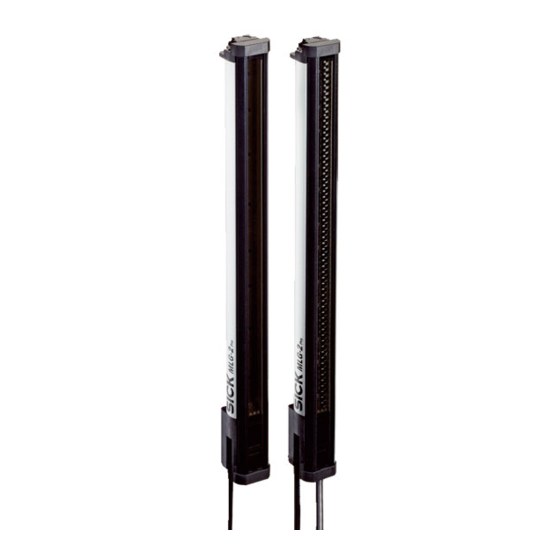
SICK WebChecker MLG-2 Operating Instructions Manual (104 pages)
Measuring automation light grid
Brand:
SICK
| Category:
Measuring Instruments
| Size: 10 MB
Table of Contents
Table of Contents
3
1 About this Document
7
Purpose of this Document
7
Scope
7
Target Group
7
Information Depth
7
Symbols Used
7
Abbreviations Used
8
2 Safety Information
9
Requirements for the Qualification of Personnel
9
Intended Use
9
General Safety Notes
10
3 Product Description
11
MLG-2 Type Label
11
Type Code
11
Sender Type Label
11
Receiver Type Label
11
Measurement Field Width
12
Configuring MLG-2 Measurement Field Width Using Type Code
12
Combinations of MLG-2 Inputs and Outputs
13
Optical Properties
14
Structure and Function
14
Device Components
15
Measurement Principle
15
Function
16
Definitions
17
Definitions for MLG-2
17
Scan Time
18
Operating Reserve
18
Scan Time, Example of Read Direction of the Connection Side
18
Minimum Object Attenuation
19
Display and Operating Elements
19
Mlg-2
19
Leds and Control Panel of the MLG-2
19
Inputs
20
Switching Inputs on the Receiver
20
Test Input on the Sender
20
Application Examples
20
MLG2 Application Examples
20
Automobile Industry, Position Detection of Rubber Bands
20
Automobile Industry, Position Detection of Material Rolls
20
Textile Industry, Width Measurement of Material Sheets
21
Textile Industry, Edge Measurement
21
Paper Industry, Edge Positioning
21
Glass Production, Position Detection of Matte Glass
21
4 Planning
22
Planning Mounting Distance between Sender and Receiver
22
Optimal Object Position
22
Identifying Optimal Object Position
23
Identifying Optimal Object Position - Example
23
Determining Measurement Accuracy for Actual Object Position
24
Accuracy of a Web Sheet - Example
24
Required Minimum Distances for an Object
25
Object Widths (Example of MLG-2 with Empty Modules)
25
Required Minimum Distances for Several Objects
26
Minimum and Maximum Object Width
26
Edge Measurement Distances
26
Edge Measurement and Edge Designation
27
Functions: Calculation of Width and Center Positions
29
Example: Measured Edges, Calculated Width
29
5 Mounting
30
Scope of Delivery
30
Mlg-2
30
Recommended Mounting Arrangements
30
Mounting with Light in Opposite Directions
30
Mounting with Light in the same Direction
30
Distances with Light in the same Direction
31
Minimum Distance from Reflective Surfaces
32
Diagram of Distances with Light in the same Direction
32
Mounting Procedure
33
Graph of Minimum Distance from Reflective Surfaces
33
Mounting the Quickfix Bracket
34
Correct Mounting
34
Examples for Incorrect Mounting
34
Mounting the Quickfix Bracket
35
Mounting the Flexfix Bracket
36
6 Electrical Installation
38
Connect the Sender and Receiver
38
T-Connector for MLG-2 Connection
41
Connecting the T-Connector
41
T-Connector Sender, Receiver, PLC
42
T-Connector, Receiver, IO-Link Master Connection
43
7 Commissioning
44
Putting the MLG-2 into Operation
44
Aligning Sender and Receiver
44
Alignment with the Quickfix Bracket
44
Performing Sensor Teach-In
45
Alignment with the Flexfix Bracket
45
Performing Material Teach-In
46
Calling up Teach-In Quality and Process Quality
46
Performing Sensor Teach-In
46
8 Operating MLG-2 Via Control Panel
48
Activating and Deactivating Pushbutton Lock
48
Aligning Sender and Receiver
48
Performing Sensor Teach-In
49
Performing Material Teach-In
49
Reset to Factory Settings
50
9 Commissioning Via SOPAS
51
Preparation
51
Device Selection
51
Installing the Software
51
Setting up MLG-2 (Installation Assistant)
51
Installation Assistant" Wizard, Sensor Alignment
52
Installation Assistant" Wizard, Sensor Teach-In - Step 1
53
Installation Assistant" Wizard, Sensor Teach-In - Step 2
53
Installation Assistant" Wizard, Sensor Teach-In Successful
53
Installation Assistant" Wizard, Material Teach-In - Step 1
55
Installation Assistant" Wizard, Material Teach-In Successful (for 10 Edges)
56
Setting up Edge Measurement
57
Parameterizing Functions: Calculation of Width and Center Positions
57
Example for Edge Measurement - Display in "Start" Tab, here 1 Object with 2 Edges
57
Other Configurations
58
Results for "Functional Configuration" Examples, "Enhanced Sensing" Page
58
10 Configuration with SOPAS
59
Start" Page
59
Device" Area
59
Overview
59
Start" Page (Example)
59
Application" Area
60
Start" Page, "Application" Area
60
Graphic Display" Area
61
Start" Page, "Graphic Display" Area
61
Histogram of Switching Output and Input Display/Blanking
62
General Device Settings" Page
63
General Device Settings" Page (Example)
63
General Settings" Area
63
Overview
63
Communication Configuration" Area
64
General Settings" Area, PIN Configuration (Example)
64
Enhanced Sensing" Page
65
Enhanced Sensing" Page (Example)
65
Overview
65
Details" Area
66
Graphic Representation of the Position and Attenuation" Area
66
Menus
66
Blanking" Menu
67
Enhanced Sensing - Menus
67
Enhanced Sensing" Page, Graphic Display of the Width
67
Graphic Display of the Width" Area
67
Sensor Alignment" Menu
67
Enhanced Sensing" Page, "Blanking" Menu (2 Examples)
68
Material Teach-In" Menu
68
Sensor Teach-In" Menu
68
Assignment of Detected Edges
70
Disappearance of Edges (E.g. Due to Band Crack)
71
Received Assignment of Edges in the Event of Band Cracks
71
Search Fields Around Edges
71
No Detection of Edges E1 and E2
72
Reinterpretation of Edge E4
72
Switching Points Inside the Search Fields
72
Without Search Fields" Device Mode
72
Edges E3 and E4 Leave the Window
73
Enhanced Sensing" Page, "Functional Configuration" Menu
73
Functional Configuration" Menu
73
Ignoring Edges E3 and E4 (Example)
73
Results for "Functional Configuration" Examples, "Enhanced Sensing" Page
74
Analog Output" Menu
75
Digital Configuration" Menu
75
Enhanced Sensing" Page, "Analog Output" Menu
75
Enhanced Sensing" Page, "Digital Configuration" Menu
76
RS-485" Menu
77
11 IO-Link
79
Configuration Via Acyclic Service Data
79
Data Storage (IO-Link)
79
Output of Process Data from the MLG-2
79
12 Rs-485
80
Application Data
80
Data Volume for Functions
81
Data Volume for the Separators
81
13 Servicing
82
14 Troubleshooting
83
Response to Faults
83
SICK Support
83
LED Indicators and Error Indicators
83
15 Decommissioning
85
Disposal
85
Returns
85
16 Technical Data
86
Data Sheet
86
Diagrams
89
Response Time
89
Response Time and Minimum Presence Time Without Smoothing
89
Minimum Presence Time with Smoothing
90
Optimal Object Position
91
Response Time with Smoothing
91
Accuracy
93
Dimensional Drawings
94
Dimensional Drawing for the MLG-2
94
Dimensions
94
17 Accessories
96
18 Annex
99
Compliance with EU Directive
99
19 List of Figures
100
20 List of Tables
102
Advertisement
SICK WebChecker MLG-2 Operating Instructions Manual (132 pages)
Measuring automation light grid with fieldbus interfaces: Ethernet/IPTM, PROFINET, EtherCAT
Brand:
SICK
| Category:
Measuring Instruments
| Size: 8 MB
Table of Contents
Table of Contents
3
1 About this Document
7
Purpose of this Document
7
Scope
7
Target Group
7
Information Depth
7
Symbols Used
7
Abbreviations Used
8
2 Safety Information
9
Requirements for the Qualification of Personnel
9
Intended Use
9
General Safety Notes
10
3 Product Description
11
Type Labels of the MLG-2 Webchecker
11
Type Code
13
Measurement Field Width
14
Switching Outputs of the MLG-2 Webchecker
15
Optical Properties
15
Structure and Function
16
Device Components
16
Measurement Principle
17
Definitions
18
Scan Time
19
Operating Reserve
19
Minimum Object Attenuation
20
Display and Operating Elements
20
Webchecker with Fieldbus Interface
20
Fieldbus Module
21
Inputs
23
Switching Inputs on the Receiver
23
Test Input on the Sender
23
Application Examples
23
Application Examples for the MLG-2 Webchecker
23
4 Planning
25
Planning Mounting Distance between Sender and Receiver
25
Identifying Optimal Object Position
26
Determining Measurement Accuracy for Actual Object Position
27
Required Minimum Distances for an Object
28
Required Minimum Distances for Several Objects
29
Minimum and Maximum Object Width
29
Edge Measurement and Edge Designation
30
Functions: Calculation of Width and Center Positions
32
5 Mounting
33
Scope of Delivery
33
Webchecker with Fieldbus Interface
33
Recommended Mounting Arrangements
33
Mounting with Light in Opposite Directions
33
Mounting with Light in the same Direction
33
Minimum Distance from Reflective Surfaces
34
Mounting Procedure
35
Mounting the Quickfix Bracket
36
Mounting the Flexfix Bracket
38
Turning the Fieldbus Module on the MLG-2
40
6 Electrical Installation
42
Fieldbus Module Connections
42
Sender Connections
44
T-Connector for MLG-2 Webchecker Connection
45
7 Commissioning
47
Putting the MLG-2 Webchecker into Operation
47
Aligning Sender and Receiver
47
Performing Sensor Teach-In
48
Performing Material Teach-In
49
Calling up Teach-In Quality and Process Quality
49
8 Operating MLG-2 Via Control Panel
51
Activating and Deactivating Pushbutton Lock
51
Alignment and Teach-In
51
Performing Sensor Teach-In
53
Performing Material Teach-In
53
Reset to Factory Settings
54
9 Commissioning Via SOPAS
55
Preparation
55
Installing the Software
55
Device Selection
55
Setting up MLG-2 Webchecker (Installation Assistant)
55
Setting up Edge Measurement
61
Parameterizing Functions: Calculation of Width and Center Positions
61
Other Configurations
62
10 The MLG-2 Webchecker in the Fieldbus Network
63
The MLG-2 in PROFINET
63
Overview
63
GSDML File
65
Function Blocks
65
The MLG-2 on the Ethercat ® Network
65
Overview
65
Integration in the Control Using an ESI File
67
Function Blocks
68
The MLG-2 on the Ethernet/Ip™ Network
68
Overview
68
Common Industrial Protocol (CIP)
70
Integration and Configuration Options
71
Error Messages of the allen Bradley Control System
75
Supported Classes
76
Identity Object
77
Assembly Object
79
Object Library
80
11 Configuration with SOPAS
86
Start" Page
86
Overview
86
Device" Area
87
Application" Area
88
Graphic Display" Area
89
General Device Settings" Page
91
Overview
91
General Settings" Area
91
Communication Configuration" Area
93
Enhanced Sensing" Page
94
Overview
94
Details" Area
95
Menus
95
Graphic Representation of the Position and Attenuation" Area
95
Graphic Display of the Width" Area
95
Enhanced Sensing - Menus
96
Sensor Alignment" Menu
96
Blanking" Menu
96
Sensor Teach-In" Menu
97
Material Teach-In" Menu
97
Functional Configuration" Menu
101
Digital Configuration" Menu
103
12 Servicing
105
13 Troubleshooting
106
Response to Faults
106
SICK Support
106
LED Displays and Error Indicators
106
14 Decommissioning
110
Disposal
110
Returns
110
15 Technical Data
111
Data Sheet
111
Webchecker Fieldbus Module Data Sheet
113
Diagrams
114
Response Time
114
Optimal Object Position
117
Accuracy
118
Dimensional Drawings
119
Webchecker Dimensional Drawing
119
Dimensional Drawings for the MLG-2 Fieldbus Module
121
16 Accessories
123
17 Annex
126
Compliance with EU Directive
126
18 List of Figures
127
19 List of Tables
129
SICK WebChecker MLG-2 Quick Manual (40 pages)
Measuring automation light grid
Brand:
SICK
| Category:
Safety Equipment
| Size: 5 MB
Table of Contents
Table of Contents
3
How to Find a New MLG-2 Light Grid as a Replacement for Your MLG-1 or XLG
4
Finding the Right MLG-2 Via the Type Code
4
Beam Separation
4
Detection Height
4
Interface and Connection Type
5
Finding a Replacement for Your XLG
6
Operating Range
6
Configuration Mode - "Software Default
6
Replacement for XLG-1
6
Type Code and Ordering Information
7
Advantages of the MLG-2 Compared to the MLG-1
8
Response Times
9
Minimum Detectable Object (MDO) - Cross-Beam Function
10
Cross-Beam Function, Operating Range 5 M - Minimum Detectable Object (Station- Ary Object) with Standard Measurement Accuracy
10
Cross-Beam Function, Operating Range 8.5 M - Minimum Detectable Object (Sta- Tionary Object) with Standard Measurement Accuracy
10
Mounting
11
Distance between Lower Edge of Housing and First Beam
11
Applications - Replacement Involving MLG-1 and MLG-2
11
Application 1
12
Application 2
13
Application 3 (PROFIBUS or Canopen)
14
Applications 1 and 3 - Distance between First Beam and Lower Edge of Housing.15 11. Application 2 - Distance between First Beam and Lower Edge of Housing
15
Overview of Brackets
15
Distance between Lower Edge of Housing and First Beam for All Applications
15
Replaceable MLG-1 and XLG-1 Brackets
16
Mounting the MLG-2 with the BEF-1SHABP004 Mounting Kit
17
Electrical Connection
19
Overview of Accessories Required
19
Accessories Required
19
Adapter Cables
20
Connecting the "AFB" Terminal Box
20
Connecting the M12 Female Connector
22
Terminals in the Terminal Box
22
Setting the Parameters for the MLG-2 in SOPAS et
24
Transferring the Parameter Settings from the MLG-1 to the MLG-2
24
Saving the MLG-1 Parameter Settings
24
Configuration
24
Mlgsetup and SOPAS et User Interfaces
26
Installation" Section
26
Configuration - Outputs" Section
27
Configuration - Light Beams" Section
32
Configuration - Inputs" Section
33
Configuration - Data Interface" Section
35
IPG Protective Pipes
36
Comparison of IPG Protective Pipe for MLG-1 and IPG2 Protective Pipe for MLG-2, Aluminum
37
List of Tables
38
Advertisement
SICK WebChecker MLG-2 Operating Instructions Manual (50 pages)
Brand:
SICK
| Category:
Measuring Instruments
| Size: 1 MB
Table of Contents
Table of Contents
3
About this Document
4
Purpose of this Document
4
Intended Use
4
Symbols
4
Description of IO-Link
5
Accessories for Visualization, Configuration, and Integration
6
Data Repository
7
Physical Layer
8
Process Data
9
PD in
9
System Status
11
Process Data Setting
11
PD out
12
Settings of Digital Outputs
13
Output Delay Setting
13
Configuring Outputs Q1-Q16
13
Service Data
26
Device Identification
26
General Device Settings
27
Analog Output Configuration
29
Definition of Functions
30
Teach-In / Detection Settings
33
Installation / Diagnostics
36
Observation of Edges
37
Device Diagnostics
40
Events
42
Application Scenarios
43
Beam Blanking
43
Teach-In
44
Sensor Teach-In
44
Material Teach-In
45
List of Abbreviations
46
Index
47
SICK WebChecker MLG-2 Technical Information (32 pages)
Smart Sensors/IO-Link, Device configuration - Advanced operating instructions
Brand:
SICK
| Category:
Accessories
| Size: 3 MB
Table of Contents
Table of Contents
3
1 About this Document
5
Purpose of this Document
5
Intended Use
5
Symbols
5
2 Description of IO-Link
6
3 Accessories for Visualization, Configuration, and Integration
7
4 Data Repository
8
5 Physical Layer
9
6 Process Data
10
PD in
10
System and Q Status + Run Length Code (RLC)
10
System and Q Status + Beam Status
10
User-Defined Process Data Content
10
System Status and Output Status
11
PD out
11
7 Service Data
12
Device Identification
12
Product Name and Manufacturer Name
12
Product Text and Serial Number
12
Definable Names
12
Hardware and Firmware Version
13
Find Me
13
Teach-In / Detection Settings for MLG-2 Devices
13
Teach-In and Beam Blanking Via Teach-In
13
Beam Blanking Mask
14
Definition of Zones
15
Performance Options
15
Process Data Setting
17
Beam Hold Functions
19
Configuring Outputs
21
System Settings
22
Installation / Diagnostics
23
Process Quality and Teach Quality
23
Device Alignment
23
Device Properties
24
Diagnostics
24
8 Events
25
Use Case
26
List of Abbreviations
30
Index
31
SICK WebChecker MLG-2 Quick Start (4 pages)
Brand:
SICK
| Category:
Measuring Instruments
| Size: 1 MB
Table of Contents
1 Operating and Status Indicators
1
2 Mounting
1
3 Electrical Installation
2
4 Commissioning
3
5 Troubleshooting
4
SICK WebChecker MLG-2 Quick Start Manual (4 pages)
Brand:
SICK
| Category:
Measuring Instruments
| Size: 0 MB
Advertisement
Related Products
SICK ML20
SICK MLS Series
SICK MLSE-0200
SICK MLSE-0300
SICK MLSE-0400
SICK MLSE-0500
SICK MLSE-0600
SICK MLS
SICK MRS1000P
SICK multiScan136
SICK Categories
Accessories
Security Sensors
Measuring Instruments
Scanner
Barcode Reader
More SICK Manuals
Login
Sign In
OR
Sign in with Facebook
Sign in with Google
Upload manual
Upload from disk
Upload from URL