Sign In
Upload
Manuals
Brands
SICK Manuals
Scanner
microScan3 Pro I/O-EFI-pro
SICK microScan3 Pro I/O-EFI-pro Manuals
Manuals and User Guides for SICK microScan3 Pro I/O-EFI-pro. We have
1
SICK microScan3 Pro I/O-EFI-pro manual available for free PDF download: Operating Instructions Manual
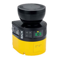
SICK microScan3 Pro I/O-EFI-pro Operating Instructions Manual (228 pages)
Safety laser scanners
Brand:
SICK
| Category:
Scanner
| Size: 20 MB
Table of Contents
Table of Contents
3
About this Document
8
Function of this Document
8
Scope
8
Target Groups of These Operating Instructions
8
Further Information
8
Symbols and Document Conventions
9
Safety Information
10
General Safety Notes
10
Laser Class 1M
10
Intended Use
11
Inappropriate Use
11
Cybersecurity
12
Requirements for the Qualification of Personnel
12
Product Description
13
Device Overview
13
Setup and Function
14
Principle of Time-Of-Flight Measurement
14
Product Characteristics
15
Variants
15
Light Pulses Scan an Area
15
Connections
16
System Plug
16
Field Types
16
Protective Field, Shown in Red in this Document
17
Reference Contour Field, Shown in Blue-Green in this Document
18
Field Set
19
Collision Protection Field, Shown in Purple in this Document, with Reference Target
19
Protective Field and Warning Field
19
Warning Field, Shown in Yellow or Orange in this Document
19
Monitoring Case
20
Yellow)
20
Monitoring Case 2 with Field Set 2
21
Simultaneous Monitoring
21
Monitoring Case 1 with Field Set 1
21
Example Applications
22
Simultaneous Monitoring
22
Hazardous Area Protection: Detection of the Presence of a Person in the Hazard- Ous Area
22
Hazardous Point Protection: Hand Detection
23
Access Protection: Detection of a Person When Accessing a Hazardous Area
23
Mobile Hazardous Area Protection: Detection of a Person When a Vehicle Approaches
24
Operator of the Machine
25
Project Planning
25
Manufacturer of the Machine
25
Assembly
26
Prevent Crawling Beneath
26
Protection from Influences
27
Prevent Stepping over
27
Preventing Unprotected Areas
28
Unsecured Areas
28
Mounting with Deflector Plates (Example)
29
Mounting in an Undercut (Example)
29
Response Time of the Safety Laser Scanner
30
Reference Contour Monitoring
30
Mounting in Vehicle Paneling (Example)
30
Overrun of the Protective Field in Front of an Opening
31
Monitoring Case Switching Time
32
Tolerance Band of the Contour as Reference Field
32
Tected Opening, Edge of the Protected Opening = Reference Contour)
32
Hazardous Area Protection
34
Stationary Application with Horizontal Scan Plane for Hazardous Area Protection.34
34
Protection against Reaching over When Mounted Low (Dimensions in MM)
37
Protection against Reaching over When Mounted High (Dimensions in MM)
38
Scan Plane at Ankle Height
39
Scan Plane at Calf Height
39
Distance of the Protective Field from the Wall
40
Hazardous Point Protection
41
Stationary Application in Vertical Operation for Hazardous Point Protection
41
Access Protection
44
Stationary Application in Vertical Operation for Access Protection
45
Mobile Hazardous Area Protection
47
Mobile Application in Horizontal Operation for Hazardous Area Protection
48
Flat-Rate Supplement ZF for Lack of Ground Clearance
49
Minimum Supplement for Lack of Ground Clearance
50
Stopping Distance as a Function of the Vehicle's Speed
51
Mobile Protection in Narrow Aisles
53
Recommended Fitting Height
53
Recommended Fitting Height for Inverted Mounting
53
Permissible Guide Tolerance of the Industrial Truck
55
Protective Field in Narrow Aisle
57
Integrating the Equipment into the Electrical Control
61
Electromagnetic Compatibility
63
Voltage Supply
64
USB Connection
64
Ossds
64
No Potential Difference between Load and Protective Device
65
Dual-Channel and Separate Connection of the Ossds of an OSSD Pair
65
Control Inputs
66
Universal Inputs, Universal Outputs, Universal I/Os
69
EFI-Pro
69
Restart Interlock
69
How the Restart Interlock Works (1): no One in Protective Field, Machine Operates
71
How the Restart Interlock Works (2): Person Detected in Protective Field, Safety Out- Put in off State
71
Restarting the Machine
72
Electrical Diagram of External Device Monitoring (EDM)
73
External Device Monitoring (EDM)
73
Network Services and Ports
73
Integration into the Network
73
Integration of the Safety Laser Scanner into the Network
74
Assemblies
75
Host-Guest Group
78
Testing Plan
79
Planning the Thorough Check During Commissioning and in Certain Situations
79
Planning the Regular Thorough Check
80
Notes on the Tests
81
Mounting
85
Safety
85
Unpacking
85
Mounting Procedure
86
Prevent Crawling Beneath
86
Prevent Stepping over
86
Changing Position of the System Plug
87
Remove the System Plug from below
88
Remove the Cover Plate from the Rear
88
Direct Mounting
89
Installing the Rear System Plug
89
Mounting the Safety Laser Scanner Directly
89
Electrical Installation
90
Safety
90
No Potential Difference between Load and Protective Device
91
Connection of the Ossds of an OSSD Pair
91
Microscan3 Pro I/O
92
Pin Assignment
92
Voltage Supply (XD1)
92
Alternative FE Connection
92
Pin Assignment of the Voltage Supply (Male Connector, M12, 4-Pin, A-Coded)
92
Connection Overview
92
Pin Assignment of Local Inputs and Outputs
93
Coded)
93
Local Inputs and Outputs 1 (XG1)
93
Network Pin Assignment (M12 Female Connector, 4-Pin, D-Coding)
93
Ethernet for EFI-Pro, Data Output, Configuration, and Diagnostics (XF1, XF2)
93
Dynamic Control Input (XG2, XG3)
94
Local Inputs and Outputs 2 (XG4)
95
Pin Assignment of Dynamic Control Input (Female Connector, M12, 8-Pin, A-Coded)
95
Pin Assignment of Inputs and Outputs 2 (Female Connector, M12, 17-Pin, A-Coded)
95
Projects
97
Installing Safety Designer
97
Safety Designer Configuration Software
97
Delivery State
97
Configuration
97
User Interface
98
Software Controls
98
User Groups
99
Settings
100
Configuration
100
Configuration
101
Networking
102
Overview
102
Functional Scope
104
Network Settings
105
EFI-Pro
105
Network Settings: EFI-Pro
105
Reading Configuration
106
Identification
107
Protocol Settings
108
EFI-Pro
108
Application
110
Monitoring Plane
111
Parameters for the Monitoring Plane
112
Parameters for the Safety Laser Scanner
114
Reference Contour Field
116
Fields
117
Using the Field Editor
118
Field Editor
118
Creating Field Set Templates
121
Importing and Exporting Field Sets and Fields
122
Background Image
122
Field Set Template
122
Settings for the Field Editor
123
Background Image
123
Editing Fields Using Coordinates
124
Editing Fields Using Coordinates
125
Drawing in Points that Cannot be Monitored
125
Area that Cannot be Monitored
126
Enable Propose Field
127
Inputs and Outputs
129
Inputs and Outputs, Local
131
Outputs
132
Inputs
132
Further Settings for some Signals
133
Monitoring Cases
135
Settings for Monitoring Case Tables
135
Several Monitoring Case Tables
137
Settings for Monitoring Cases
137
Input Condition
137
Cut-Off Paths
138
Assigning Field Sets
138
Importing and Exporting Monitoring Case Tables
139
Simulation
140
Data Output
141
Transfer
142
Starting and Stopping Safety Function
143
Reports
144
Report
144
Service
145
Device Restart
145
Managing Passwords
146
Factory Settings
146
Ethernet/Ip
146
Access Management
147
Optics Cover Calibration
148
Commissioning
149
Safety
149
Alignment
149
Switching on
150
Alignment about the Transverse Axis
150
Alignment about the Depth Axis
150
Check During Commissioning and Modifications
151
Status Leds
151
Operation
152
Safety
152
Regular Thorough Check
152
Status Indicators
152
Status Leds
152
Leds
152
Status Leds
153
Network Leds
153
Status Indicator with the Display
155
Maintenance
159
Safety
159
Regular Cleaning
159
Replacing the Optics Cover
160
Fixing Screws for the Optics Cover
161
Replacing the Safety Laser Scanner
162
Replacing the Safety Laser Scanner Without System Plug
163
Replacing the System Plug
164
Completely Replacing the Safety Laser Scanner
164
Replacing the System Plug
165
Regular Thorough Check
165
Troubleshooting
166
Safety
166
Detailed Diagnostics Using the Display
166
Pushbuttons on the Device
166
Fault Indication on the Display
168
Fault Display
168
Diagnostics Using Safety Designer
171
Data Recorder
172
Event History
173
Message History
175
Status Inputs and Outputs
175
Decommissioning
177
Disposal
177
Data Sheet
178
Microscan3 Pro I/O
178
Technical Data
178
Version Numbers and Functional Scope
178
Variant Overview
178
Response Times
186
Course of the OSSD Test over Time
188
Switch-Off Tests
188
Sensing Range
189
Duration and Time Offset for the Switch-Off Tests in an OSSD Pair
189
Scanning Range and Object Size for Warning Fields (Devices with a Max. Protective Field Range of 4.0 M and Devices with Max. Protective Field Range of 5.5 M)
190
Data Exchange in the Network
194
Assemblies
194
Dimensional Drawings
205
Ordering Information
206
Scope of Delivery
206
System Plug
207
Additional Spare Parts
207
Safety Laser Scanner Without System Plug
207
Spare Parts
207
Accessories
208
Brackets
208
Alignment Aid
208
Cleaning Agent
208
Test Rods
208
Additional Accessories
208
Glossary
210
Annex
215
Conformities and Certificates
215
Compliance with EU Directives
215
Note on Standards
215
Checklist for Initial Commissioning and Commissioning
216
Mounting Methods for Protection from Interference from Systems in Close Proximity
217
List of Figures
220
List of Tables
223
Advertisement
Advertisement
Related Products
SICK microScan3 - EFI-pro
SICK microScan3-EtherNet/IP
SICK microScan3-EFI-pro
SICK microScan3-PROFINET (M12)
SICK microScan3 Core I/O
SICK microScan3 - PROFINET
SICK microScan3 Core I/O AIDA
SICK microScan3 Pro I/O
SICK microScan3-EtherCAT
SICK microScan3-PROFINET
SICK Categories
Accessories
Security Sensors
Measuring Instruments
Scanner
Barcode Reader
More SICK Manuals
Login
Sign In
OR
Sign in with Facebook
Sign in with Google
Upload manual
Upload from disk
Upload from URL