Sign In
Upload
Manuals
Brands
SICK Manuals
Analytical Instruments
MCS200HW
SICK MCS200HW Manuals
Manuals and User Guides for SICK MCS200HW. We have
3
SICK MCS200HW manuals available for free PDF download: Service Manual, Operating Instructions Manual
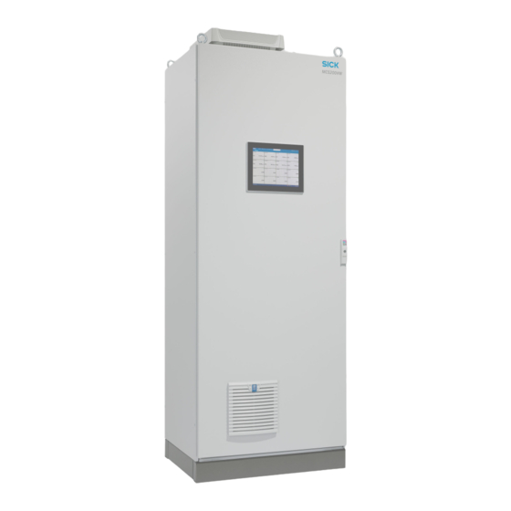
SICK MCS200HW Service Manual (146 pages)
Multicomponent Analysis System
Brand:
SICK
| Category:
Measuring Instruments
| Size: 21 MB
Table of Contents
Table of Contents
3
1 About this Manual
7
Target Group of this Manual
7
Purpose of this Manual
7
Information Concerning this Manual
7
Special Hazards
8
Safety Rules for Work on Electrical Systems
8
Esd
8
Inquiries to SICK AG
9
2 Tools
10
Special Tools and Auxiliary Means
10
3 Maintenance
11
Maintenance Interval
11
Expendable and Wearing Parts
11
Working on the Device Cabinet
12
Exchanging Filter Pads
12
Door Ventilator
12
Roof Ventilator
13
Working on the Cell
14
Removing the Complete Cell
15
Fitting the Complete Cell
18
Cell Inlet Filter Maintenance
21
Replacing the Non-Return Valve on the Cell Inlet Filter
25
Ejector Block Maintenance
26
Replacing the O-Ring on the Middle Section
29
Replacing the Sealing Ring on Hose Connection 2
30
Replacing the O-Rings on Exhaust Gas Connection and Ejector Nozzle
31
Mirror Plates and Tubes Maintenance
33
Replacing the O-Ring of the Upper Mirror Plate
34
Replacing the O-Rings of the Lower Mirror Plate
37
Tubes Maintenance
40
Working on the Sender/Receiver Unit
43
Replacing the Filter Mat on the Ventilator
43
Opening the Sender/Receiver Unit
44
Replacing the Drying Agent
44
4 Functional Test
46
IR Components, Drift Check
46
Oxygen Sensor Drift Check
46
Beamer Current Check
47
Reference Energy Check
47
Test Signal Transmission
48
Setting the IP Address
48
MODBUS Simulation
49
Test Analog and Digital Inputs and Outputs
50
Analog Outputs
50
Digital Outputs
50
Analog Inputs
51
Digital Inputs
51
5 Repairs
52
Working on the Device Cabinet
52
Replacing the Door Fan
52
Replacing the Pressure Reducer Unit
54
Replacing the CAN Node
55
Working on the Valve Manifold
57
Replacing the Valve Manifold
57
Replacing the Valve
58
Replacing the IO Module
59
Replacing the Test Gas Valves
60
Replacing the Display
62
Replacing the 24V Power Supply Unit
63
Working on the Cell
65
Removing the Complete Cell
65
Fitting the Complete Cell
68
Replacing the Oxygen Sensor
70
Replacing Mirror Plates
73
Replacing the Upper Mirror Plate
73
Replacing the Lower Mirror Plate
76
Replacing the Heating Cartridges
79
Replacing the PT100 Temperature Sensor
82
Replacing the Thermostatic Switch
85
Working on the Sender/Receiver Unit
88
Removing the Electronics Housing Cover
88
Replacing the Beamer
89
Resetting the Beamer Service Life
90
Resetting the Reference Energy
91
Removing the Complete Sender/Receiver Unit
93
Fitting the Complete Sender/Receiver Unit
98
Replacing the Fan
98
Replacing the Pressure Control Module
99
Replacing the Complete Beamer Unit
102
Performing Optical Adjustment
103
Replacing the Chopper Motor
105
Replacing the Filter Wheel Motor
107
Filter Wheel Motor 1
108
Filter Wheel Motor 2
111
Filter Wheel Motor 3
113
Replacing the Lens on Filter Wheel Housing 1
116
Replacing the LPMS03 Detector Cable
117
Replacing the LPMS03 Detector Circuit Board
118
Replacing the Cable and Light Barrier on the Filter Wheel Motor
120
Replacing the LPMS04 Circuit Board
121
Replacing the Heating Cartridges
122
Replacing the PT100 Temperature Sensor
125
Replacing the Sender/Receiver Windows
127
Adjusting the Zero Point
128
Working on the Electronics Unit
129
Removing and Fitting the Electronics Unit
129
Replacing the LPMS01 Circuit Board
132
Replacing the LINUX CPU
135
Performing a Firmware Update
137
Swapping the SD Card
138
Replacing the LPMS02 Circuit Board
139
Replacing the LPMS02 Fan
142
Replacing the LPMS01 to LPMS04 Connection Cable
145
Advertisement
SICK MCS200HW Operating Instructions Manual (74 pages)
Multicomponent Analysis System
Brand:
SICK
| Category:
Analytical Instruments
| Size: 5 MB
Table of Contents
Table of Contents
3
About this Document
7
Function of this Document
7
Scope of Application
7
Target Groups
7
Further Information
7
Symbols and Document Conventions
7
Warning Symbols
7
Warning Levels / Signal Words
8
Information Symbols
8
Data Integrity
8
Safety Information
9
Basic Safety Information
9
Warning Information on Device
10
Intended Use
11
Requirements on the Personnel's Qualification
11
Product Description
13
Product Identification
13
Gas Supply Terminology
14
Layout and Function
14
System Overview
14
Analyzer Cabinet
15
Gas Sampling Unit
17
Sample Gas Line, Heated
17
Instrument Air, Conditioning
18
Integrated GMS811 Fidori (Option)
18
Cooling Unit (Option)
19
Extended Interfaces (Option)
19
Remote Maintenance (Option)
19
Transport and Storage
20
Transport
20
Storage
21
Mounting
22
Safety
22
Scope of Delivery
22
Overview of Mechanical and Electrical Installation
22
Installation Sequence
23
Installing the Analyzer Cabinet
23
Installing the Sample Gas Line
24
Laying the Sample Gas Lines
24
Connecting the Heated Sample Gas Line to the Analyzer
25
Installing the Stainless Steel Screw Fitting
25
Using a Push-In Fitting (Pneumatic)
26
Laying the Hose Bundle Line
26
Connecting the Signal Lines on the Analyzer
27
Setting the Pressure Reducer Module
27
Connecting the Valve Block
28
Connecting the Span Gases
29
Connecting the Exhaust Gas Outlet
30
Electrical Installation
31
Safety
31
Equipment Protection
31
Disconnecting Device
31
Socket for Service Work
31
Connecting the Power Supply
31
Performing a High Voltage Test
32
Connecting the Signal Line (Option)
32
Connecting Ethernet (Option)
33
Commissioning
34
Prerequisites for Switching on
34
Switching on
34
Recognizing the Safe Operating State
34
Adjusting
34
Performing Zero Point Adjustment
34
Performing Reference Point Adjustment
35
Adjustment with Internal Adjustment Filter
35
Adjustment with Span Gas
35
O 2 Adjustment
36
Operation
37
Operating Concept
37
User Groups
37
Display
37
Tiles
38
Measuring Screen
39
Menus
41
Password
41
Menu Tree
41
Maintenance
45
Safety
45
Important Information
45
Cleaning
46
Clean Surfaces and Parts with Media Contact
46
Cleaning the Display
47
Maintenance Plan
47
Checking the System
48
Check Assemblies
48
Check External Instrument Air Supply
48
Check Span Gases
49
Check Environment
49
Check Gas Sampling Unit
49
Check Measured Values (When System in Operation)
49
Maintaining the Instrument Air Conditioning
49
Maintaining the Instrument Air Conditioning (Option)
49
Maintaining the External Instrument Air Conditioning (Option)
49
Replacing the Filter Pad
50
Replacing the Filter Mat of the Roof Fan Grill
50
Replacing the Filter Pad
51
Troubleshooting
52
Safety
52
Important Information
52
Error Messages and Possible Causes
52
Replacing the Electronics Module Filter Pad
57
Decommissioning
58
Switching off
58
Shutdown
58
Return Delivery
58
Shipping for Repair
58
Cleaning the Device before Returning
59
Transport
59
Disposal
59
Technical Data
60
Dimensional Drawings
60
Technical Data
62
Measured Values
62
Ambient Conditions
63
Housing
64
Interfaces and Protocols
64
Power Supply
64
Gas Supply
65
Tube Connections
65
Sample Gas Conditions
65
Connections in Analyzer
66
Power Supply - Connection / Fuses
66
Electronics Fuses
66
Connections for Heated Components
67
Connections for Interfaces and SD Card
69
Heated Sample Gas Line
71
Switching on the Circuit Breakers Again
71
Torques for Screw Fittings
71
Annex
73
Conformities
73
Licenses
73
Liability Disclaimer
73
Software Licences
73
Source Codes
73
SICK MCS200HW Operating Instructions Manual (62 pages)
Multicomponent Analysis System
Brand:
SICK
| Category:
Analytical Instruments
| Size: 4 MB
Table of Contents
Table of Contents
3
1 About this Document
6
Function of this Document
6
Scope of Application
6
Target Groups
6
Further Information
6
Symbols and Document Conventions
6
Warning Symbols
6
Warning Levels / Signal Words
7
Information Symbols
7
Data Integrity
7
2 Safety Information
8
Basic Safety Information
8
Warning Information on Device
8
Intended Use
9
Responsibility of User
9
User Qualification
10
3 Product Description
11
Product Identification
11
Gas Supply Terminology
11
Layout and Function
12
Analyzer Cabinet
14
Gas Sampling Unit
15
Heated Sample Gas Line
15
Hose Bundle Line
15
Instrument Air Conditioning (Option)
15
Integrated GMS811 Fidori (Option)
16
Extended Interfaces (Optional)
16
Remote Maintenance (Optional)
16
4 Transport and Storage
17
Transport
17
Protective Measures for Long-Term Storage
18
5 Mounting
19
Safety
19
Scope of Delivery
19
Checklist for Mechanical and Electrical Installation
19
Installing the Analyzer Cabinet
20
Assembly Information for Sample Gas Lines and Hose Bundle Line
20
Installation Sequence
21
Connect the Sample Gas Line to the Analyzer
21
Tube Screw Fittings
22
Connecting the Signal Lines to the Analyzer
22
Setting the Pressure Reducer Module
22
Connecting the Valve Block
23
Connecting the Span Gases
24
Connect Sample Gas Outlet
25
6 Electrical Installation
26
Safety
26
Equipment Protection
26
Disconnecting Device
26
Socket for Service Work
26
Electrical Connections
26
7 Commissioning
28
Before Switching on
28
Switching on
28
Recognizing the Safe Operating State
28
Adjusting
28
Performing Zero Point Adjustment
28
Performing Reference Point Adjustment
29
8 Operation
31
Operating Concept
31
User Groups
31
Display
31
Tiles
32
Measuring Screen
33
9 Menus
34
Password
34
Menu Tree
34
10 Maintenance
38
Important Information
38
Information on Span Gases
39
Cleaning
39
Maintenance Plan
40
Checking the System
40
Maintaining the Instrument Air Conditioning
41
Replacing the Filter Pads
42
11 Troubleshooting
44
Important Information
44
Error Messages and Possible Causes
45
Measured Values Erroneous
48
Replacing the Electronics Filter Pad
48
12 Decommissioning
49
Switch-Off States
49
Shipping for Repair
49
Transport
50
Disposal
50
13 Technical Data
51
Dimension Drawings
51
Technical Data
52
Measuring Parameters
52
Ambient Conditions
53
Design
53
Interfaces and Protocols
54
Voltage Supply
54
Supply Gases
55
Tube Connections
55
Sample Gas Conditions
55
Heated Sample Gas Lines
55
Connections in Analyzer
56
Circuit Breakers
59
Torques
60
14 Annex
61
Conformities
61
Licences
61
Advertisement
Advertisement
Related Products
SICK MCS200HW-MP
SICK MCS300P
SICK MCS100E
SICK MCR
SICK MCS100FT
Sick MAX48
SICK MITSUBISHI ELECTRIC MELSEC iQ-F Series
SICK MSL Series
SICK MLSE-0200
SICK ReLy MULT1
SICK Categories
Accessories
Security Sensors
Measuring Instruments
Scanner
Barcode Reader
More SICK Manuals
Login
Sign In
OR
Sign in with Facebook
Sign in with Google
Upload manual
Upload from disk
Upload from URL