Sign In
Upload
Manuals
Brands
SICK Manuals
Measuring Instruments
GM700 Ex
SICK GM700 Ex Manuals
Manuals and User Guides for SICK GM700 Ex. We have
3
SICK GM700 Ex manuals available for free PDF download: Operating Instructions Manual, Instruction Manual
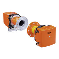
SICK GM700 Ex Operating Instructions Manual (108 pages)
Gas Analyzer, Cross-Duct Version
Brand:
SICK
| Category:
Measuring Instruments
| Size: 6 MB
Table of Contents
Table of Contents
3
1 About this Document
7
Function of this Document
7
Scope of Application
7
Target Groups
7
Further Information
7
Data Integrity
7
Symbols and Document Conventions
8
Warning Symbols
8
Warning Levels / Signal Words
8
Information Symbols
9
2 Safety Information
10
Main Operating Information
10
Warning Information on the Device
13
Intended Use
14
Purpose of the Device
14
Responsibility of User
14
3 Product Description
16
Product Identification
16
Product Characteristics
16
Type Plate
16
Device Variants
17
Pressure and Temperature Sensor
17
Options
17
Layout and Function
18
Function of the Pressurized Enclosure
19
Purge Air Unit
19
Check Cycle
19
Explosion Protection in Accordance with ATEX
20
Operation in Potentially Explosive Atmosphere
20
Zone of Use of GM700 Ex 3G Components
21
Pressurized Enclosure System
21
Sender/Receiver Unit - Evaluation Unit Connecting Hose
22
4 Transport and Storage
23
Remove the Transport Safety Device
23
Storage
23
5 Mounting
24
Information on Installation in Potentially Explosive Atmospheres
24
Tools Required
25
Material Required
25
Preparing the Sampling Point
25
GM700 Ex Scope of Delivery
26
Installation Sequence
26
Installation Example
26
Overview of Installation Steps (Duct-Side Preparation)
27
Installing the Flange with Tube
28
Install the Evaluation Unit
32
Installing the Purge Air Unit
34
6 Electrical Installation
35
Electrical Installation Safety Information
35
Connection Overview
38
Lines
38
Connecting Interfaces
39
Connect I/O Interfaces
39
Connecting the Connecting Hose to the SR-Unit on the Evu
42
Connecting Pressure, Temperature and Purge Air Monitor
42
Preparing the Power Supply
42
Connecting the FS840 Ex Overpressure Control
43
Electrical Connection of SR-Unit
45
Connecting the Potential Equalization
45
Connecting the Potential Equalization on the SR-Unit
46
Connecting the Potential Equalization on the Purge Air Fixture
46
Potential Equalization - Evaluation Unit and Ex Control Unit
46
7 Commissioning
48
Safety Information on Commissioning
48
Prerequisites for Successful Commissioning
48
Material Required
49
Overview of Commissioning Steps
49
Assembly Drawing
50
Zero Adjust on the Measuring Path Free from Sample Gas
51
Setting up the Zero Path
51
Fit the Purge Air Fixtures
51
Aligning Device Flanges and Purge Air Fixtures
52
Fitting the Purge Air Fixtures on the Flange with Tube
53
Fitting the Device Flange on the Purge Air Fixture
54
Feeding Protective Gas
56
Connecting the Protective Gas on the SR-Unit
56
Switch the Pressurized Enclosure on
57
Fitting the Sender/Receiver Unit and Reflector Unit on the Device Flange
57
Optical Fine Alignment of the Sender/Receiver Unit
58
Fitting the Weather Hood (Option)
59
Starting Measuring Operation
61
Operating States
61
Select the Ambient Temperature Range
62
8 Operation
63
Safety
63
Check before Start-Up
63
Operating and Display Elements (Evaluation Unit)
63
Function Buttons
64
Menu Tree of the Evaluation Unit
65
Menu Tree, Measuring
65
Menu Tree Diagnosis
65
Menu Tree Parameter
66
Menu Tree Calibration
68
Menu Tree Maintenance
68
Operating Using the Serial Interface
69
Significance of Command Line Elements
69
Setting for Serial Interfaces
69
Serial Interface Command - MEAS
69
Serial Interface Commands - Diag
70
Setting the Display Contrast
70
9 Maintenance
72
Safety
72
Maintenance Plan
74
Expendable, Wearing and Spare Parts
75
Preparatory Work
75
Function Test of the Pressurized Enclosure System
75
Maintenance Work on the FS840
76
Repair Work on the FS840
76
Removing the SR-Unit Resp. Reflector Unit
76
Visual Check of the Sender/Receiver Unit and Evaluation Unit
77
Cleaning the Optical Interfaces
78
Etalon Tool
79
Filter Box Measurement to Check the Measuring Channels (for Dry Gases)
79
Checking the Gas Analyzer with Test Cell GMK10
82
Checking the Evaluation Unit
83
Cleaning the Purge Air Unit
83
10 Troubleshooting
85
Safety
85
Monitoring and Diagnostic System
86
Device Not Functioning
87
Evaluation Unit Not Functioning
87
Communication Fault between Evaluation Unit and Receiver
88
Ex Operation Malfunction
88
Error Messages
88
Warning Messages
90
Repairing Inadequate Purge Air Supply
90
Corrosion on Flange
91
11 Decommissioning
92
Safety Information for Decommissioning
92
Decommissioning Ex-Relevant Subassemblies
93
Removing the Device
93
Preparing the Device Ready for Shipping
94
Environmentally Compatible Disposal
95
12 Technical Data
96
System: GM700 Ex Version 3G / Zone 2
96
Sender/Receiver Unit
96
Reflector Unit GM700
97
Purge Air Fixture
97
Evaluation Unit Ex Version
97
Technical Data for Pressurized Enclosure System
98
Technical Data Energy Supply
98
Limit Values for Terminal Assignment FS840
98
Technical Data for Protective Gas
98
Technical Data for Enclosure
98
Pressurized Enclosure System Settings
98
Dimension Drawings: Sender/Receiver Unit
100
Dimension Drawing, Reflector Unit
101
Dimension Drawings, Purge Air Fixtures, Without Electronics
102
Dimension Drawing, Purge Air Unit
103
Dimension Drawings, Evaluation Unit with Pressurized Enclosure System FS840
104
Dimension Drawing, Flange with Tube, DN125
104
Dimension Drawing, Weather Hoods
105
13 Annex
106
Conformities
106
Electrical Protection
106
Ex Certifications
106
Possible Ambient Temperatures
106
Ambient Temperature Ranges
106
Advertisement
SICK GM700 Ex Operating Instructions Manual (102 pages)
Laser Gas Analyzer, Version with Measuring Probe
Brand:
SICK
| Category:
Measuring Instruments
| Size: 8 MB
Table of Contents
Table of Contents
3
1 About this Document
7
Function of this Document
7
Scope of Application
7
Target Groups (and Document Structure)
7
Further Information
7
Data Integrity
7
Symbols and Document Conventions
8
Warning Symbols
8
Warning Levels / Signal Words
8
Information Symbols
9
2 Safety Information
10
Main Operating Information
10
Warning Information on the Device
13
Intended Use
14
Purpose of the Device
14
Responsibility of User
14
3 Product Description
16
Product Identification
16
Product Characteristics
16
Type Plate
16
Device Variants
17
Pressure and Temperature Sensor
17
Options
17
Layout and Function
17
Function of the Pressurized Enclosure
18
Purge Air Unit
18
Check Cycle
19
Explosion Protection in Accordance with ATEX
20
Operation in Potentially Explosive Atmosphere
20
Zone of Use GM700 Ex 3G Components
21
Pressurized Enclosure System
22
Safety Functions
22
Sender/Receiver Unit - Evaluation Unit Connecting Hose
22
GMP Measuring Probe in Detail
23
4 Transport and Storage
24
Transport Protection
24
Storage
25
5 Mounting
26
Information on Installation in Potentially Explosive Atmospheres
26
Tools Required
27
Material Required
27
Preparing the Sampling Point
27
GM700 Ex Scope of Delivery
28
Installation Sequence
28
Installation Example
28
Overview of Installation Steps (Duct-Side Preparation)
29
Installing the Flange with Tube
29
Install the Evaluation Unit
31
Install the FS840
31
Installing the Purge Air Unit
33
6 Electrical Installation
34
Electrical Installation Safety Information
34
Connection Overview
36
Lines
37
Connecting Interfaces
38
Connect I/O Interfaces
38
GM700 Ex 3G Terminal Connection Diagram
38
Electrical Connection of the Evaluation Unit Evu
40
Connecting the Connecting Hose to the SR-Unit on the Evu
41
Connecting Pressure, Temperature and Purge Air Monitor
41
Preparing the Power Supply
41
Connecting the FS840 Ex Overpressure Control
42
Electrical Connection of SR-Unit
44
Connecting the Potential Equalization
44
Connecting the Potential Equalization on the SR-Unit
45
Connecting the Potential Equalization on the Measuring Probe
45
Potential Equalization - Evaluation Unit and Ex Control Unit
46
7 Commissioning
47
Safety Information on Commissioning
47
Prerequisites for Successful Commissioning
47
Material Required
48
Overview of Commissioning Steps
48
Zero Adjust
49
Fitting the SR-Unit on the Measuring Probe
49
Aligning the Measuring Probe in Flow Direction
51
Feeding Protective Gas
52
Connecting the Protective Gas on the SR-Unit
52
Switch the Pressurized Enclosure on
54
Optical Fine Alignment of the Sender/Receiver Unit
54
Installing the Weatherproof Cover
55
Starting Measuring Operation
56
Operating States
57
Select the Ambient Temperature Range
57
8 Operation
58
Safety
58
Check before Commissioning
58
Operating and Display Elements (Evaluation Unit)
58
Function Buttons
59
Menu Tree of the Evaluation Unit
60
Menu Tree Measuring
60
Menu Tree Diagnosis
60
Menu Tree Parameter
61
Menu Tree Calibration
63
Menu Tree Maintenance
63
Operating Using the Serial Interface
64
Significance of Command Line Elements
64
Setting for Serial Interfaces
64
Serial Interface Command - MEAS
64
Serial Interface Commands - Diag
65
Call up the Table with Error Messages
65
View the Device Configuration
65
Check the System State and Configuration
65
Call up Diagnostic Data
65
Setting the Display Contrast
65
9 Maintenance
67
Safety
67
Maintenance Plan
69
Expendable, Wearing and Spare Parts
70
Preparatory Work
70
Function Test of the Pressurized Enclosure System
70
Maintenance Work on the FS840
71
Repair Work on the FS840
71
Removing the Sender/Receiver Unit
71
Visual Check of the Sender/Receiver Unit and Evaluation Unit
72
Cleaning the Optical Interfaces
73
Etalon Tool
74
Filter Box Measurement to Check the Measuring Channels (for Dry Gases)
75
Checking the Evaluation Unit
77
Cleaning the Purge Air Unit
78
10 Troubleshooting
79
Safety
79
Monitoring and Diagnostic System
80
Device Not Functioning
81
Evaluation Unit Not Functioning
81
Communication Fault between Evaluation Unit and Receiver
82
Ex Operation Malfunction
82
Error Messages
82
Warning Messages
84
Repairing Inadequate Purge Air Supply
85
Corrosion on Flange
85
11 Decommissioning
86
Safety Information for Decommissioning
86
Decommissioning Ex-Relevant Subassemblies
87
Removing the Device
87
Preparing the Device Ready for Shipping
88
Environmentally Compatible Disposal
89
12 Technical Data
90
System: GM700 Ex Version 3G / Zone 2
90
Sender/Receiver Unit
90
Measuring Probe
91
Evaluation Unit Ex Version I/O Module
91
Technical Data for Pressurized Enclosure System
92
Technical Data Energy Supply
92
Limit Values for Terminal Assignment FS840
92
Technical Data for Protective Gas
92
Technical Data for Enclosure
92
Pressurized Enclosure System Settings
92
Dimension Drawings: Sender/Receiver Unit
94
Dimension Drawings: Open Measuring Probe (GMP)
95
Dimension Drawing, Purge Air Unit
96
Dimension Drawings, Evaluation Unit with Pressurized Enclosure System FS840
97
Dimension Drawings: Mounting Flange DN125
97
Dimension Drawing, Weatherproof Cover, Sender/Receiver Unit
98
13 Annex
99
Conformities
99
Electrical Protection
99
Ex Certifications
99
Possible Ambient Temperatures
99
Ambient Temperature Ranges
99
SICK GM700 Ex Instruction Manual (60 pages)
Brand:
SICK
| Category:
Analytical Instruments
| Size: 17 MB
Advertisement
Advertisement
Related Products
SICK GM700
SICK GM700-02
SICK GM700-03
SICK GM700-04
SICK GM700-05
SICK GM700-07
SICK GM700-08
SICK GM700-09
SICK GM32-1
SICK GM32-9
SICK Categories
Accessories
Security Sensors
Measuring Instruments
Scanner
Barcode Reader
More SICK Manuals
Login
Sign In
OR
Sign in with Facebook
Sign in with Google
Upload manual
Upload from disk
Upload from URL