Sign In
Upload
Manuals
Brands
SICK Manuals
Media Converter
AHS36 IO-Link
SICK AHS36 IO-Link Manuals
Manuals and User Guides for SICK AHS36 IO-Link. We have
4
SICK AHS36 IO-Link manuals available for free PDF download: Operating Instructions Manual, Mounting Instructions
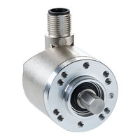
SICK AHS36 IO-Link Operating Instructions Manual (107 pages)
Absolute Encoder
Brand:
SICK
| Category:
Media Converter
| Size: 3 MB
Table of Contents
Table of Contents
3
1 About this Document
6
Function of this Document
6
Target Group
6
Information Depth
6
Scope
7
Abbreviations Used
7
Symbols Used
8
2 On Safety
9
Authorized Personnel
9
Intended Use
9
Table 1: Authorized Personnel
9
General Safety Notes and Protective Measures
10
Environmental Protection
10
Table 2: Disposal of the Assemblies
10
3 Quick Start Instructions on the AHS36/AHM36 Canopen
11
Node ID/Baud Rate
11
Figure 1: Encoder in the Canopen Network
11
Parameterization
12
EDS File
12
Save or Restore Parameters
12
Process Data Objects (Pdos)
13
PDO Communication
13
PDO Mapping
14
4 Product Description
15
Special Features
15
Figure 2: Connection Types
15
Table 3: Special Features of the Encoder Variants
16
Operating Principle of the Encoder
17
Scaleable Resolution
17
Preset Function
17
Figure 3: Saving the Offset
17
Round Axis Functionality
18
Figure 4: Example Position Measurement on a Rotating Table with Transmission Ratio
18
Figure 5: Example Position Measurement on a Rotating Table Without Transmission Ratio
19
Electronic Cam Mechanism
20
Controls and Status Indicators
20
Figure 6: Example Electronic Cam Mechanism
20
Figure 7: Position of the LED
20
5 Integration in Canopen
21
Communication Profile
21
Canopen in the OSI Model
21
Communication Channels
21
Figure 8: Canopen in the OSI Model
21
Topology
22
Figure 9: Communication Channels
22
Figure 10: Ahx36 in the Canopen Topologie
22
Node Ids and COB-Ids
23
Table 4: Communication Object Identifier for the Encoder
23
Baud Rate
24
Layer Setting Services (LSS)
24
Table 5: Supported Baud Rates
24
Table 6: Format of an LSS Telegram
25
Table 7: Format of the Switch Mode Global Command
25
Table 8: Format of the Configure Node ID Command
25
Table 9: Response to the Configure Node ID Command
25
Table 10: Format of the Configure Bit Timing Parameters Command
26
Table 11: Baud Rate Table
26
Table 12: Response to the Configure Bit Timing Parameters Command
26
Table 13: Format of the Store Configuration Command
27
Table 14: Response to the Store Configuration Command
27
Table 15: Format of the Inquire LSS Address Service Command
27
Table 16: Command Table
27
Table 17: Response to the Inquire LSS Address Service Command
27
Network Management (NMT)
28
Canopen State Machine
28
Table 18: Format of the Identify Non Configured Slave Device Command
28
Table 19: Response to the Identify Non-Configured Slave Device Command
28
Table 20: Status of the Canopen State Machine
28
Network Management Services
29
Figure 11: Transitions between the Operating Statuses
29
Table 21: Format of the NMT Telegram
29
Table 22: Meaning of Byte 0
29
Boot-Up Message
30
Node Guarding and Heartbeat
30
Table 23: Transitions between the Operating Statuses
30
Table 24: Format of the Node Guarding Telegram
30
Table 25: Meaning of Byte 0
30
Service Data Objects (SDO)
31
Table 26: Format of the Heartbeat Telegram
31
Table 27: Meaning of Byte 0
31
Figure 12: Example for Transmit SDO and Receive SDO
32
Table 28: Format of the SDO
32
Process Data Objects (PDO)
33
PDO Mapping
33
Figure 13: Example for Transmit PDO and Receive PDO
33
Table 29: Format of the Transmit Pdos
33
Table 30: Example for a Transmit PDO
33
PDO Data Transmission
34
Table 31: Example for the Communication Parameters
34
Asynchronous or Synchronous Formation of the Position
36
Figure 14: Sending Transmit Pdos
36
Configurable Functions
37
EDS File
37
Figure 15: EDS File
37
Scaling Parameters
38
Figure 16: Objects 6000H, 6001H and 6002H in Twincat
38
Figure 17: Example for the Parameterization of Object 6000H
38
Table 32: Example for Binary Code
38
Figure 18: Example for the Parameterization of Object 6001H
39
Figure 19: Example for the Parameterization of Object 6002H
39
Table 33: Examples for Total Resolution
39
Preset Function
40
Figure 20: Example for the Parameterization of Object 6003H
40
Cyclic Process Data
41
Figure 21: Example for the Parameterization of Object 2005H
41
Figure 22: Example for the Parameterization of Object 1A00H
41
Table 34: Example for Binary Code
41
Speed Measurement
42
Figure 23: Example for the Parameterization of Subindex 1A00.01H
42
Figure 24: Example for the Parameterization of Object 2002H
42
Round Axis Functionality
43
Figure 25: Example for the Parameterization of Subindex 2002.02H
43
Figure 26: Example for the Parameterization of Object 2001H
43
Figure 27: Example for the Parameterization of Subindex 2001.03H
44
Electronic Cam Mechanism
45
Figure 28: Objects for the Electronic Cam Mechanism
45
6 Object Library
46
Nomenclature
46
Table 35: Nomenclature of the Access Types and Data Types
46
Standard Objects
47
Table 36: Implemented Standard Objects
47
Detailed Information on the Standard Objects
48
Table 37: Object 1000H
48
Table 38: Object 1000H - Details
48
Table 39: Object 1001H
48
Table 40: Object 1001H - Details
48
Table 41: Object 1003H
49
Table 42: Object 1003H - Details
49
Table 43: Object 1005H
49
Table 44: Object 1005H - Details
49
Table 45: Object 1008H
50
Table 46: Object 1009H
50
Table 47: Object 100Ah
50
Table 48: Object 100Ch
50
Table 49: Object 100Dh
50
Table 50: Object 1010H
51
Table 51: Object 1010H - Details
51
Table 52: Object 1011H
52
Table 53: Object 1011H - Details
52
Table 54: Object 1014H
52
Table 55: Object 1015H
52
Table 56: Object 1017H
53
Table 57: Object 1018H
53
Table 58: Object 1018H - Details
53
Process Data Objects
54
Basic PDO Structure
54
Table 59: Structure of the Pdos
54
Table 60: Structure of the Pdos - Details
54
Parameter of the Receive PDO
55
Table 61: Object 1400H
55
Table 62: Object 1600H
55
Parameter of the Transmit Pdos
56
Table 63: Object 1800H
56
Table 64: Object 1801H
56
Table 65: Object 1802H
57
Table 66: Object 1803H
57
Transmission Types
58
Table 67: Transmission Types
58
Table 68: Object 1A00H - Default Subindices
58
Table 69: Object 1A01H - Default Subindices
59
Table 70: Object 1A02H - Default Subindices
59
Table 71: Object 1A03H - Default Subindices
59
Objects and Their Subindices that Can be Mapped
60
Table 72: Objects and Their Subindices that Can be Mapped
60
Encoder Profile Specific Objects
61
Table 73: Implemented Encoder Profile Specific Objects
61
Encoder Parameters
62
Table 74: Object 6000H
62
Table 75: Object 6000H - Details
62
Table 76: Object 6001H
63
Table 77: Object 6002H
63
Table 78: Object 6003H
63
Table 79: Object 6004H
64
Table 80: Object 6030H
64
Table 81: Object 6200H
64
Objects for the Electronic Cam Mechanism (CAM)
65
Table 82: Object 6300H
65
Table 83: Object 6300H - Details
65
Table 84: Object 6301H
66
Table 85: Object 6301H - Details
66
Table 86: Object 6302H
67
Table 87: Object 6301H - Details
67
Table 88: Object 6310H
68
Table 89: Object 6320H
68
Table 90: Object 6330H
68
Objects for Diagnostics
69
Table 91: Object 6500H
69
Table 92: Object 6500H - Details
69
Table 93: Object 6501H
69
Table 94: Object 6502H
69
Table 95: Object 6503H
70
Table 96: Object 6503H - Details
70
Table 97: Object 6504H
70
Table 98: Object 6504H - Details
70
Table 99: Object 6505H
71
Table 100: Object 6505H - Details
71
Table 101: Object 6506H
72
Table 102: Object 6506H - Details
72
Table 103: Object 6507H
72
Table 104: Object 6507H - Details
72
Table 105: Object 6508H
73
Table 106: Object 6509H
73
Table 107: Object 650Ah
73
Table 108: Object 650Bh
73
Manufacturer-Specific Objects
74
Table 109: Implemented Manufacturer-Specific Objects for the Encoder Configuration
74
Table 110: Implemented Manufacturer-Specific Objects that Provide Status Information
74
Objects for the Encoder Configuration
75
Table 111: Object 2000H
75
Table 112: Object 2000H - Details
75
Table 113: Object 2001H
76
Table 114: Object 2002H
77
Table 115: Object 2004H
78
Table 116: Object 2004H - Service Codes
78
Table 117: Object 2005H
78
Table 118: Object 2006H
79
Table 119: Object 2007H
80
Table 120: Object 2007H - Cos_Flag-XX Status
80
Objects that Provide Status Information
81
Table 121: Object 2008H
81
Table 122: Object 2009H
81
Table 123: Object 2010H
81
Table 124: Object 2010H - State Flag 1 (S_STAT-A)
83
Table 125: Object 2010H - State Flag 2 (S_STAT-B)
83
Table 126: Object 2010H - State Flag 3 (S_STAT-C)
83
Table 127: Object 2011H
84
Table 128: Object 2012H
85
Table 129: Object 2013H
87
Table 130: Object 2014H
87
Table 131: Object 2015H
87
Table 132: Object 2016H
87
Table 133: Object 2017H
87
Table 134: Object 2018H
88
Table 135: Object 2019H
88
7 Commissioning
89
Electrical Installation
89
Connection of the AHS36/AHM36 Canopen
89
Figure 29: Connection Types
89
Settings on the Hardware
90
Figure 30: Male Connector of the AHS36/AHM36 Canopen
90
Table 136: Pin Assignment of the Connection Plug/Core Color on the Connecting Cable
90
Table 137: Maximum Length of the Stubs
90
Configuration
91
Default Delivery Status
91
System Configuration
91
Figure 31: Integration in Twincat® with EDS File
91
Figure 32: Context Menu Scan Boxes
92
Figure 33: Encoder in the Device Tree
92
Figure 34: Advanced Settings Dialog Box
92
Figure 35: Configuration Mode Button
93
Figure 36: Configuration Mode Prompt
93
Figure 37: Load I/O Devices Prompt
93
Figure 38: Free Run Prompt
93
Figure 39: Status Indication for the Free Run Mode or Configuration Mode
93
Figure 40: Online Tab
94
Tests before the Initial Commissioning
95
8 Fault Diagnosis
96
In the Event of Faults or Errors
96
SICK STEGMANN Support
96
Error and Status Indications on the LED
96
Figure 41: Position of the LED
96
Meaning of the LED Displays
97
Diagnostics Via Canopen
97
Emergency Messages
97
Table 138: Meaning of the LED Displays
97
Table 139: Emergency Message Format
97
Alarms, Warnings and Status
98
Table 140: Error Codes and Error Registers
98
Error During the SDO Transfer
99
Table 141: Error During the SDO Transfer
99
9 Annex
100
Conformity with EU Directives
100
10 List of Illustrations
101
11 List of Tables
103
Advertisement
SICK AHS36 IO-Link Operating Instructions Manual (94 pages)
Brand:
SICK
| Category:
Media Converter
| Size: 2 MB
Table of Contents
Table of Contents
3
About this Document
6
Scope
6
Function of this Document
6
Target Group
6
Information Depth
6
Symbols Used
7
Abbreviations Used
7
Safety Information
9
Authorized Personnel
9
Intended Use
9
General Safety Notes and Protective Measures
10
Environmental Protection
10
Quick Start Instructions on the AHS/AHM36 Canopen and AHS/AHM36 Canopen Inox
11
Node ID/Baud Rate
11
Parameterization
12
EDS File
12
Save or Restore Parameters
12
Process Data Objects (Pdos)
13
PDO Communication
13
PDO Mapping
13
Product Description
14
Special Features
14
Operating Principle of the Encoder
15
Scaleable Resolution
15
Preset Function
15
Round Axis Functionality
16
Electronic Cam Mechanism
18
Controls and Status Indicators
18
Integration in Canopen
19
Communication Profile
19
Canopen in the OSI Model
19
Communication Channels
19
Topology
20
Node Ids and COB-Ids
20
Baud Rate
21
Layer Setting Services (LSS)
22
Network Management (NMT)
25
Canopen State Machine
25
Network Management Services
26
Boot-Up Message
27
Node Guarding and Heartbeat
27
Service Data Objects (SDO)
29
Process Data Objects (PDO)
30
PDO Mapping
31
PDO Data Transmission
31
Asynchronous or Synchronous Formation of the Position
33
Configurable Functions
34
EDS File
34
Scaling Parameters
35
Preset Function
37
Cyclic Process Data
38
Speed Measurement
39
Round Axis Functionality
40
Electronic Cam Mechanism
41
Object Library
44
Nomenclature
44
Standard Objects
44
Detailed Information on the Standard Objects
45
Process Data Objects
50
Basic PDO Structure
51
Parameter of the Receive PDO
51
Parameter of the Transmit Pdos
52
Transmission Types
54
Objects and Their Subindices that Can be Mapped
56
Encoder Profile Specific Objects
57
Encoder Parameters
58
Objects for the Electronic Cam Mechanism (CAM)
60
Objects for Diagnostics
63
Manufacturerspecific Objects
67
Objects for the Encoder Configuration
68
Objects that Provide Status Information
73
Commissioning
82
Electrical Installation
82
Connection of the AHS/AHM36 Canopen and AHS/AHM36 Canopen Inox
82
Settings on the Hardware
83
Configuration
83
Default Delivery Status
83
System Configuration
84
Tests before the Initial Commissioning
88
Fault Diagnosis
89
In the Event of Faults or Errors
89
Support
89
Error and Status Indications on the LED
89
Meaning of the LED Displays
89
Diagnostics Via Canopen
90
Emergency Messages
90
Alarms, Warnings and Status
91
Error During the SDO Transfer
91
Annex
93
Conformities and Certificates
93
Compliance with EU Directives
93
Compliance with UK Statutory Instruments
93
SICK AHS36 IO-Link Mounting Instructions (24 pages)
Absolute encoder
Brand:
SICK
| Category:
Media Converter
| Size: 1 MB
Table of Contents
Montageanleitung
2
Table of Contents
4
Zu diesem Dokument
5
Zu Ihrer Sicherheit
5
Sicherheitshinweise
5
Schirmung
5
Anschluss an das Netzwerk
5
PIN- und Aderbelegung
6
Bedeutung der LED-Anzeige
7
Gerätehandling IM Netzwerk
7
Montage
8
Encoder mit Servoflansch
8
Encoder mit Klemmflansch
10
Encoder mit Flansch für Aufsteckhohlwelle
11
Anhang
12
Konformitäten und Zertifikate
12
Mounting Instructions
13
Mounting Instructions
14
About this Document
16
Safety Information
16
Safety Notes
16
Screen
16
Connection to the Network
16
PIN and Wire Assignment
17
Meaning of the LED Display
18
Device Handling in the Network
18
Mounting
19
Encoder with Servo Flange
19
Encoder with Face Mount Flange
21
Encoder with Flange for Blind Hollow Shaft
22
Annex
23
Conformities and Certificates
23
Advertisement
SICK AHS36 IO-Link Operating Instructions Manual (8 pages)
Brand:
SICK
| Category:
Media Converter
| Size: 0 MB
Table of Contents
Elektrische Installation
2
Bedienung
4
About this Document
5
Safety Information
5
Mounting
5
Encoder with Servo Flange
5
Mounting Via Threaded Holes on the Flange Side (Fig. 1)
5
Mounting with Servo Clamps (Fig. 2)
5
Encoder with Face Mount Flange
5
Mounting Via Threaded Holes on the Flange Side (Fig. 3)
5
Mounting Via the Mounting Spigot (Fig. 4)
5
Encoder with Flange for Blind Hollow Shaft (Fig. 5 and 6)
5
Electrical Installation
6
Connecting the Device Electrically
6
IO-Link Specific Information
6
Physical Layer
6
Process Data
6
Service Data
6
Operation
8
Operating and Status Indicators
8
Annex
8
Conformities
8
Advertisement
Related Products
SICK AHM36 IO-Link
SICK AHS36 CANopen
SICK AHM36 CANopen
SICK AHS36 CANopen Inox
SICK AHM36 CANopen Inox
SICK AHS/AHM36 SAE J1939
SICK AFM60 PROFINET
SICK AFS60S Pro
SICK AFM60S Pro
SICK ATM 60-C Series
SICK Categories
Accessories
Security Sensors
Measuring Instruments
Scanner
Barcode Reader
More SICK Manuals
Login
Sign In
OR
Sign in with Facebook
Sign in with Google
Upload manual
Upload from disk
Upload from URL