Sign In
Upload
Manuals
Brands
Shimadzu Manuals
Laboratory Equipment
GC-2014
Shimadzu GC-2014 Manuals
Manuals and User Guides for Shimadzu GC-2014. We have
4
Shimadzu GC-2014 manuals available for free PDF download: Instruction Manual, Operation Manual, Service Manual
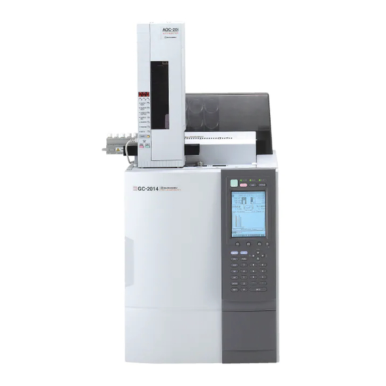
Shimadzu GC-2014 Instruction Manual (318 pages)
Gas Chromatograph
Brand:
Shimadzu
| Category:
Laboratory Equipment
| Size: 3 MB
Table of Contents
Table of Contents
5
1 Installation
13
Verification of Installation Location
13
Power Supply and Wiring
16
Gas Supply Plumbing
19
2 Before Use
29
Setting Analytical Flow Lines
29
Outputting Analog Signals to the Chromatopac
32
Outputting Digital Signals to a Personal Computer
35
Connecting a RS-232C Cable to the Chromatopac C-R8A
37
Connecting Auto Injector/Auto Sampler AOC-20 Series
39
Connecting the Relay Terminals
41
3 Installing Packed Columns and Setting Analytical Flow Lines
43
Installation Location for Packed Columns
43
Dual-Column Packed FID Analysis
45
Single-Column Packed FID Analysis
48
Packed TCD Analysis
51
Packed Analysis Using the Single DET
54
4 Installing Capillary Columns and Setting Analytical Flow Lines
59
Installation Location for Capillary Columns
59
Capillary Analysis Using the Dual FID (When a Detector Adapter with Purge Is Used)
61
Capillary Analysis Using the Dual FID (When a Makeup Gas Flow Controller Is Used)
64
Capillary TCD Analysis
66
Single DET
70
5 Analysis
73
Analysis Flow Chart
73
Preparation
73
Setting Parameters
73
Analysis
74
Notes for Analysis
75
6 Basic Key Operation
79
Keypad Description and Operation
79
Keypad Operation
80
Screen
81
Status Indicators
82
Adjusting the Display
83
Basic Key Operations
84
Screen Display
84
Moving the Cursor
85
Entering Numeric Values
86
Changing a Selection
86
Changing Item Names
87
Getting Help
89
Screen Description
89
PF Menu
89
7 Starting and Stopping the GC [SYSTEM]
91
SYSTEM] Key Main Screen
91
Screen Description
91
Parameter
92
PF Menu
93
Specifying Clean up Parameters
94
Screen Description
94
Parameter List
95
PF Menu
97
Specifying Start Procedures
98
Screen Description
98
Parameter List
99
Example: Starting the System with Carrier Gas Flow
99
Specifying the Stop Procedures
100
Screen
100
Parameter List
100
System Shut down Examples
101
8 Setting the Analytical Parameters and File Management
103
SET] Key Main Screen
103
Main Screen
103
Parameter List
104
PF Menu
106
File Management
107
Screen Description
107
PF Menu
107
Copying a File
108
Renaming a File
108
Initializing a File
109
Specifying the Analytical Flow Line Components ([Line Config])
110
Screen Description
110
Changing Items Displayed with [Customiz]
113
Screen Description
113
9 Monitoring the GC
115
MONIT] Key Main Screen
115
Screen Description
115
Parameter List
117
PF Menu
117
Monitoring the Temperature with [Temp Mon]
118
Screen Description
118
PF Menu
118
Monitoring the Flow Rate with [Flow Mon]
119
Screen Description
119
PF Menu
119
Zero Point Adjustment
120
Screen Description
120
10 Starting and Stopping Analysis
121
Making an Injecting and Starting an Analysis
121
Verifying the Gas Chromatograph Status
121
Making Manual Injection
122
Starting the Analysis
123
Terminating the Analysis
124
External Devices
124
11 Creating an Oven Temperature Program
125
COL] Key Main Screen
125
Screen Description
125
Parameter List
126
PF Menu
126
Temperature Programs
127
Isothermal Analysis
127
Programmed Analysis
127
Creating a Temperature Program
127
12 Injection Port
131
Packed Column Injection Port (Dual INJ)
131
Setting the Temperature with [INJ] Key
132
Setting the Flow Rate
134
Entering Columns Parameters
136
Creating a Flow Rate Program
137
Split/Splitless Injection System
138
Setting the Temperature with [INJ] Key
139
Setting the Flow Rate with [FLOW] Key
141
Setting Column Parameters
145
Gas Saver
146
Pressure Program
147
Creating a Flow Rate Program
149
Split Ratio Program
151
Septum Purge
153
High Pressure Injection and Splitter Fix Mode
155
Direct Injection System
157
Setting the Temperature
158
Setting the Flow Rate
159
AFC and APC Offset Calibration
161
Setting the Flow Rate Parameters
162
13 Detector
165
Hydrogen Flame Ionization Detector (FID)
165
Principle of FID Operation
165
Setting the Detector
166
Setting the Detector Gas (Manual Flow Controller)
169
Setting the Detector Gas Flows(APC)
171
Igniting and Extinguishing the FID
173
Thermal Conductivity Detector (TCD)
176
Principle of TCD Operation
176
Setting the Detector
177
TCD Zero Point Adjustment
181
Filter Signal Time Constant
182
Background Compensation
183
14 Diagnosis
185
Standard Diagnosis
185
Screen Description
185
PF Menu
185
Diagnosis Parameters
186
Diagnosis Parameter List
187
Starting the Diagnosis
189
PF Menu
189
Stopping/Exiting the Diagnosis
190
PF Menu
190
Diagnosis Results
191
PF Menu
191
Log Reading Menu
193
Screen Description
193
Parameter List
193
GC Operation Log
194
Analysis Log
195
Parameter Log
197
Error Log
198
Diagnostic Log
199
Analysis Counter
200
Screen Description
200
Parameter List
201
PF Menu
201
Coolant Consumption Counter
202
Screen Description
202
Parameter List
203
PF Menu
203
Standard Installation Test
204
Screen Description
204
PF Menu
204
Test Procedure
205
Peak Generator
206
Screen Description
206
Parameter List
206
PF Menu
206
15 Optional Devices
207
Auto Injector Parameters
207
Screen Description
207
Parameter List
208
PF Menu
209
AOC Priority Analysis
210
Parameter List
210
PF Menu
211
Other AOC Parameters
211
Other AOC Parameter
212
PF Menu
213
Auto-Sampler Carousel and Other Optional Parameters
214
Parameter List
214
Setting AUX Temperature
215
Screen Description
215
Parameter List
215
PF Menu
215
On/Off Setting
216
On/Off Parameter List
216
Setting the AUX APC Parameters
217
Screen Description
217
Parameter List
218
PF Menu
218
Setting the AUX AMC Parameters
219
Screen Description
219
Parameter List
220
PF Menu
220
Setting the CRG Parameters
221
Screen Description
221
Parameter List
222
PF Menu
222
16 Special Functions
223
Time Scheduler
223
Description Screen
223
Parameter List
223
Setting the Mode
224
Editing a Time Schedule
225
PF Menu
225
Creating a New Time Schedule
226
PF Menu
226
Parameters Available in the Time Scheduler
227
Changing Schedule Parameters
227
Time Schedule Example
228
Starting/Stopping a Time Schedule
229
PF Menu
229
Copying and Deleting a Time Schedule
230
Batch Schedule
231
Screen Description
231
Parameter List
232
PF Menu
232
Creating a New Batch Schedule
233
Parameter List
234
PF Menu
235
Editing a Batch Schedule
235
Batch Processing Setup Example
236
Time Program
237
Screen Description
237
PF Menu
237
Creating a New Time Program
238
PF Menu
238
Time Program Parameters
239
Editing a Time Program
240
Time Program Setup Example
241
Pre-Run Program
243
Screen Description
243
PF Menu
243
Creating a New Pre-Run Program
244
Editing a Pre-Run Program
244
After Pre-Run Program Is Finished
244
Pre-Run Program Set up Example
245
Direct Operation
246
Screen Description
246
Parameter List
246
PF Menu
246
GC Configuration
247
Screen Description
247
Parameter List
247
Setting the Date and Time
248
Setting the Maximum Temperature Limits
249
Setting Transmission Parameters
250
Setting the Ready Check Parameters
251
Parameter Configuration
253
Customizing Component Names
258
Setting the Link Device Code
262
Temperature Offset
263
Other Settings
264
Service and Maintenance
267
Screen Description
267
Parameter List
267
Installation (Position)
268
Installation (Piping)
270
Initialization
273
Power Consumption
274
Stopwatch
275
Screen Description
275
PF Menu
275
Timing with Inverse Measurement
275
Key Lock and Parameter Lock
276
Screen Description
276
Key Locking
277
Parameter Locking
278
ROM Version no
281
Screen Description
281
Parameter List
281
17 Printing
283
Connection to Chromatopac
283
Parameters to be Printed
283
AOC Commands
287
Program Parameters
289
Event no
291
18 Error Messages
295
System Errors
295
Temperature Control Errors
298
Pressure/Flow Rate Errors
301
Communication Errors
305
Detector Errors
306
Program Errors
308
Operations Errors
309
Optional Device Error (AOC-20I/S)
312
Warning Messages
313
Advertisement
Shimadzu GC-2014 Operation Manual (148 pages)
Gas Chromatograph
Brand:
Shimadzu
| Category:
Laboratory Equipment
| Size: 2 MB
Table of Contents
Introduction
3
Important
3
Notice
3
GC Models and Supplied Equipment
4
Safety-Related Signal Words
4
Safety Precautions
5
Gas Usage Precautions
7
Installation Location
9
In the Event of an Emergency or Power Outage
10
Precaution for Maintenance
11
Warranty
12
After-Sales Service and Availability of Replacement
13
Maintenance, Inspection, and Servicing
13
Disposal Precautions
13
Electromagnetic Compatibility
14
Table of Contents
15
1 General
19
Features
20
Names of Components
21
Specifications
28
2 Before Using GC-2014
31
Verifying Package
32
Handling of Instrument
34
Opening/Closing Column Oven Door
34
Power ON/OFF
34
Removing INJ/DET Cover
35
Opening Flow Controller Cover
35
Screen Operation
38
Displaying Main Screen
38
Displaying Sub Screen
39
Switching PF Menus
39
Moving Cursor
40
Operation When You Have Multiple Choices
41
Screen Help
42
Analysis Using Packed Column
44
Preparation
44
Installing SUS (Stainless Steel) Packed Column in Oven
46
Installing Septum to Injection Port
50
Installing Glass Packed Column in Oven
52
Checking Gas Leak
56
External Device Setup
58
Setting for Analysis
59
Actual Analysis
64
Analysis Using Capillary Column
67
Preparation
67
Installation to Injection Port
71
Installing Adaptor
74
Installing Capillary Column in Oven
77
Checking Gas Leak
81
External Device Setup
83
Setting for Analysis
84
Actual Analysis
90
AOC (Optional) Setting
93
Specifying AOC
93
Starting AOC
94
TCD Setting
95
Screen Description
95
Zero Point Adjustment for TCD
96
4 Maintenance and Inspection
97
Parts for Maintenance
98
If You Are Using Packed Column
98
If You Are Using Capillary Column
100
Inspection/Maintenance Intervals
101
General Maintenance Procedures
102
If You Are Using Packed Column
102
If You Are Using Capillary Column
104
Septum
105
If You Are Using Packed Column
105
If You Are Using Capillary Column
106
O-Ring for Glass Insert
107
If You Are Using Capillary Column
107
Glass Insert
109
If You Are Using Packed Column
109
If You Are Using Capillary Column
110
Graphite Ferrule
112
If You Are Using Packed Column
112
If You Are Using Capillary Column
113
Packed Column
114
Capillary Column
115
Flow Controller (SPL, WBI Only)
116
Maintenance Intervals
117
Maintenance Procedures
117
Trap Inspection
117
Trap Replacement
118
Conditioning Molecular Sieve Filter
118
Fid
119
Maintenance Intervals
119
Maintenance Procedures
120
Removing/Installing Igniter
120
FID Jet
121
Removing FID Parts
121
Removing FID High Voltage Unit
122
Removing FID Jet
123
Installing FID Jet
123
Trouble Shooting
126
Error Messages (Extract)
138
How to Use CD-ROM
143
About the Provided CD-ROM
143
To Read the Instruction Manual in CD-ROM
143
Key Function List
144
Shimadzu GC-2014 Service Manual (122 pages)
Brand:
Shimadzu
| Category:
Laboratory Equipment
| Size: 2 MB
Table of Contents
Disclaimer
2
Product Guarantee
2
Introduction
3
Notation Used for Precautionary Information
3
Table of Contents
5
Chapter 1 Installation
9
Installation Space
9
Rear Space
9
Side Space
9
Installation Environment
9
Ambient Temperature and Humidity
9
Installation Surface
10
Corrosive Gas and Dust
10
Influence of Electromagnetic Waves and Power-Supply Noise
10
Other Precautionary Items
10
Power Supply
11
Power-Supply Voltage
11
Power-Supply Capacity
11
Gas
12
Purity
12
Supply Pressure
12
Chapter 2 Configuration of Gc-2014
13
Configuration Diagrams for GC-2014 Series
13
Gc-2014A
13
Gc-2014Af
14
GC-2014Afsc
15
Gc-2014Afspl
15
Gc-2014At
16
Gc-2014Atf
17
Gc-2014Atfspl
18
Structure of GC-2014
24
External Appearance
24
Structure Diagram 1
25
Structure Diagram 2
26
Structure Diagram 3
27
Sensor and Thermocouple
27
Heater and PT Sensor/Thermocouple
28
Fan Motor
28
Fan
29
Structure of Oven Cooling Unit
30
Electric Circuits
31
Block Diagram
31
CPU Unit
32
Power Unit
37
TCD Controller
41
FID Controller
44
ECD Controller
51
FPD Controller
54
FTD Power Controller
58
Pcb aux Temp
61
Chapter 3 Gas-Flow Controller
63
Configuration Diagrams for Gas-Flow Controller
63
Afc
63
Apc
73
3Ch APC
73
2Ch APC
74
1Ch APC
75
Flow-Line Diagram for Gas-Flow Controller
76
Chapter 4 Sample Injection Unit
79
Configuration Diagrams for Sample Injection Unit
79
Piping for Sample Injection Unit
80
Configuration of Injection Unit
81
Heater Resistance Values for HEATER, PT ASSY, SPL, 100 and HEATER
82
Assy, Spl, 230
82
Recognized Resistance Values for HEATER, PT ASSY, SPL, 100 and HEATER, PT ASSY, SPL, 230
82
Precautions for Replacing HEATER, PT ASSY, SPL, 100 and HEATER
82
Packed Dual Injector
83
Chapter 5 Detector Unit
85
Tcd
85
Det Heater Assy, Ft
86
Fid
87
Det Heater Assy, F
88
Ecd
89
Fpd
91
Ftd-2014C
93
Ftd-2014
95
Chapter 6 Maintenance Parts Lists
99
Gc-2014 Main Unit
99
Fid-2014, Single
100
Fpd-2014
100
Ftd-2014, Capillary
101
Ftd-2014, Packed
101
Ecd-2014
101
Tcd-2014
102
D-Fid
102
D-Inj
102
Other
102
Chapter 7 Troubleshooting
103
Gas and Pressure/Flow-Rate Settings
103
Precautions for Flow-Rate Control Settings (CAR)
103
When the Control Mode Is "SPLIT" or "SPLITLESS
103
When the Control Mode Is "TOTAL FLOW" and the Injection Mode Is
106
Direct
106
When the Control Mode Is "PRESS" or "LINEAR VELOCITY" and the Injection Mode Is "DIRECT
106
Precautions for Flow-Rate Control Settings (Detapc)
108
Temperature Control
109
Detector
109
Fid
109
Fpd
110
Ftd
110
Chromatogram and Data
110
Other Problems
111
Chapter 8 Service Window
113
Flow Adjust (CAR)
114
Flow Adjust (Detapc)
115
Flow Adjust (aux APC)
115
Temp. Sensor Use Time
116
Mode
116
Serial Number
117
Main Body Serial Number
117
Unit Serial Numbers
118
Maintenance Log
118
Fan & LCD Use Time
119
Init. for Shipment
119
Chapter 9 Appendix
121
Advertisement
Shimadzu GC-2014 Service Manual (98 pages)
Brand:
Shimadzu
| Category:
Laboratory Equipment
| Size: 1 MB
Table of Contents
Notice
2
Product Warranty
2
Introduction
3
Listing of Part Numbers
3
Maintenance Parts Availability
3
Conventions Used for Precautionary Information
4
Table of Contents
5
Chapter 1 Installation
9
Installation Space
9
Rear Space
9
Side Space
9
Installation Environment
9
Ambient Temperature and Humidity
9
Installation Surface
10
Corrosive Gas and Dust
10
Influence of Electromagnetic Waves and Power-Supply Noise
10
Other Precautionary Items
10
Power Supply
11
Power-Supply Voltage
11
Power-Supply Capacity
11
Gas
12
Purity
12
Supply Pressure
12
Work Related Precautions
12
Chapter 2 Configuration of GC-2014
13
Configuration Diagrams for GC-2014 Series
13
Gc-2014A
13
Gc-2014Af
14
GC-2014Afsc
15
Gc-2014Afspl
15
Gc-2014At
16
Gc-2014Atf
17
Gc-2014Atfspl
18
Structure of GC-2014
24
External Appearance
24
Structure Diagram 1
25
Structure Diagram 2
26
Structure Diagram 3
27
Sensor and Thermocouple
27
Heater and PT Sensor/Thermocouple
28
Fan Motor
28
Fan
29
Structure of Oven Cooling Unit
30
Electric Circuits
32
Block Diagram
32
Function of each Board
33
Power Unit: Functional Block Diagram
34
Detector Controller: Functional Block Diagram
34
PCB Key Assembly: Functional Block Diagram
35
List of Controllers
36
Auxiliary Temperature Control
36
Chapter 3 Gas-Flow Controller
37
Configuration Diagrams for Gas-Flow Controller
37
Afc
37
Manual Flow Controller
39
Fid
39
Ftd
41
Fpd
43
Aux
45
APC (Optional)
46
3Ch APC
46
2Ch APC
47
Chapter 4 Sample Injection Unit
49
Configuration of Sample Injection Unit
49
Piping for Sample Injection Unit
50
Configuration of Injection Unit
51
Assy, Spl, 230
52
Packed Dual Injector
53
Chapter 5 Detector Unit
55
Tcd
55
Det Heater Assy, Ft
56
Fid
57
Det Heater Assy, F
58
Ecd
59
Fpd
61
Ftd-2014C
63
Ftd-2014
66
Chapter 6 Maintenance Parts List
69
Consumables
69
GC-2014 Main Unit
69
FID-2014 Single
69
Fpd-2014
69
FTD-2014 Capillary
69
FTD-2014 Packed
70
Maintenance Parts
71
GC-2014 Main Unit
71
FID-2014 Single
72
Fpd-2014
72
FTD-2014 Capillary
73
FTD-2014 Packed
73
Ecd-2014
73
Tcd-2014
73
Dfid
74
Wbi-2014
74
Sinj
74
Dinj
74
Others
74
Chapter 7 Troubleshooting
75
Gas and Pressure/Flowrate Settings
75
Precautions for Flowrate Control Settings (CAR)
75
When the [Control Mode] Is [SPLIT] or [SPLITLESS]
75
When the [Control Mode] Is [PRESS] or [VELOCITY] and the [Split Mode] Is
78
When the [Control Mode] Is [Total Flow] and the [Split Mode] Is [DIRECT]
78
[Direct]
78
Precautions for Flowrate Control Settings (Detapc)
80
Temperature Control
81
Detector
81
Fid
81
Fpd
82
Ftd
82
Chromatogram and Data
82
Other Problems
83
Chapter 8 Service Window
85
Flow Adjust (CAR)
86
Flow Adjust (Detapc) (Options Only)
87
Flow Adjust (aux APC)
87
Temp. Sensor Use Time
88
Mode
88
Serial Number
89
Main Body Serial Number
89
Unit Serial Numbers
90
Maintenance Log
90
Fan & LCD Use Time
91
Init. for Shipment
91
Chapter 9 Appendix
93
GC-2014 Update Software Instruction Manual
93
Overview
93
Using Flush ROM Update
93
Updating the GC-2014
93
Changes from the Previous GC-2014 Model
95
Advertisement
Related Products
Shimadzu GC-2014A
Shimadzu GC-2014AF
Shimadzu GC-2014AFsc
Shimadzu GC-2014AFSPL
Shimadzu GC-2014AT
Shimadzu GC-2014ATF
Shimadzu GC-2014ATFSPL
Shimadzu GC-2010 Plus
Shimadzu GC-8AIT
Shimadzu GCMS-QP2010 Series
Shimadzu Categories
Laboratory Equipment
Measuring Instruments
Scales
Security Sensors
Medical Equipment
More Shimadzu Manuals
Login
Sign In
OR
Sign in with Facebook
Sign in with Google
Upload manual
Upload from disk
Upload from URL