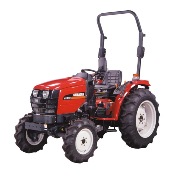
Shibaura ST333 Workshop Manual
Hide thumbs
Also See for ST333:
- Brochure & specs (6 pages) ,
- Specification sheet (1 page) ,
- Operator's manual (72 pages)

Related Manuals for Shibaura ST333


Summary of Contents for Shibaura ST333
- Page 1 WORKSHOP MODEL MANUAL ST330/ST333 NOTE: This WORKSHOP MANUAL for the Tier 3 ENGINE of ST330 and ST333 Tractor. Chapter 1 GENERAL Chapter 2-ENGINE Chapter 3-TRACTOR MAIN BODY 64...
- Page 2 MANUAL ST330/ST333 NOTE: Chapter 1-GENERAL This WORKSHOP MANUAL for the Tier 3 ENGINE of ST330 and ST333 Tractor. 1-1 External View 1-2 Specification & Performances 1-3 Precautions Before Servicing 1-4 Basic Understanding on Servicing 1-5 Sequence of Dismantling the Tractor...
-
Page 3: Table Of Contents
INDEX Chapter 1 GENERAL …………………………………………………………………………………..1 1-1 External Views ……….……….………………..……………………………………………………….…..2 1-2 Specifications & Performance ………………………………………..……..…………………………..3 1-3 Precautions Before Servicing ……….…………………………...……….……………………………..5 1-4 Basic Understanding on Servicing ………..…………………………………………..…..……………..5 …………..…..…..………………..…………………….………...6 1. METRIC BOLT TORQUE SPECIFICATIONS 1-5 Sequence of Dismantling the Tractor ………………………………..…………………..……………..7 1. FLOW CHART………………………………..…………………..………………………………………..7 2. - Page 4 Introduction In order to refine the Shibaura tractor series furthermore, ST series tractors were developed this time. These are economical tractors provided with practical functions and high power. They meet users’ needs according efficient economical specifications requiring no after-care. This manual describes structure, functions, maintenance and service procedures for the ST tractors to obtain their functions fully and for safe operation.
- Page 5 Chapter 1. GENERAL...
-
Page 6: External Views
1-1 External Views 002Y Unit: mm Model ST 330 (9 × 3) 1115 2825 2490 1390 1600 1150 ST 333 (953~1345) (9 × 3) ST 330 (HST) 2825 2425 1500 1600 1100 1155 ST 333 (HST) - Page 7 Rear 499 mm 555 mm PTO Shaft Rotating Direction Clockwise as seen from output end side Model N843 (ST330) N843 (ST333) Type Water-Cooled 4-Cycle Vertical Diesel Engine Number of Cylinders Total Stroke Volume N843 - 1496cc Continuous Rated Speed 2,800 rpm Compression Ratio 22.2...
- Page 8 The ground speeds are engine speed at 2800 rpm with 11.2-24 Rear Tires On Manual Transmission. The ground speeds are engine speed at 2800 rpm with 13.6-16 Rear Tires On Model HST Transmission. Manual Transmission Hydrostatic Transmission Gear Range Main Position AG Tire Turf Tire...
-
Page 9: Precautions Before Servicing
1-3 Precautions Before Servicing (1) Have the tractor washed clean and have the oil, fuel, and cooling water drained out depending on the work required. (2) Service shop should always be kept clean to prevent dust from rising and should be well lit. (3) The disassembled parts should have the oil and grease washed off and arranged on a stand separated by groups. -
Page 10: Metric Bolt Torque Specifications
1. METRIC BOLT TORQUE SPECIFICATIONS Coarse Thread Fine Thread Bolt Size Grade No. Kilo-gram Newton- Pitch (mm) Newton Meters Pitch (mm) Kilo-gram Meters Meters Meters 4T, 4.8 4.9-6.9 0.5-0.6 7T, 8T, 8.8 8.3-11.3 0.85-1.15 - - - - - - - - - - - - - - - 10T, 11T 11.7-15.7... -
Page 11: Sequence Of Dismantling The Tractor
1-5 Sequence of Dismantling the Tractor 1. FLOW CHART 1) Manual Transmission Model Hydrostatic Transmission Model Front axle Front axle Engine Engine Clutch case Clutch case Transmission Transmission (Front) Transmission (Rear) Rear axle Hydraulic cylinder case Rear axle Hydraulic cylinder case... - Page 12 2. ENGINE AND HST UNIT REMOVAL (9 × 3 and HST) DISASSEMBLY 1) STEERING WHEEL, INSTRUMENT PANEL ① Remove the cap, retaining nut and spring washer. ② Pull the steering wheel. ③ Pull the instrument panel and disconnect the main wire harness, speed meter cable and combination switch connector.
- Page 13 5) AIR CLEANER ASSEMBLY ① Un tighten the hose band of the intake manifold. ② Remove the air cleaner assembly from the air cleaner support. 009Y 6) RADIATOR ASSEMBLY ① Remove the radiator supports. ② Untighten the hose bands and disconnect the radiator hoses.
- Page 14 9) FUEL TANK ① Disconnect the two fuel return hoses from the top of the fuel tank. ② Disconnect the fuel supply line from the fuel shut-off valve and drain the fuel from the tank into a clean container. ③ Disconnect the electrical connectors from the fuel level sender unit.
- Page 15 12) DIVERTER VALVE ① Remove the banjo bolts and disconnect the sump return from the diverter valve disconnect the other end from the sump. ② Disconnect the system pressure line from the diverter valve and the lift cover. ③ Remove the diverter valve. 017Y 13) RUBBER AND DRIVE SHAFT ①...
- Page 16 16) HST PIPING, OIL COOLER, OIL FILTER WITH BASE (HST MODEL) ① Remove the clamps for HST piping. ② Release the hose bands and remove the banjo bolts, pipings and oil filter with base. ③ Remove the brackets and oil cooler from on the radiator. ④...
- Page 17 19) POWER STEERING CONTROL VALVE, COLUMN ① Remove the cruise control assembly from the steering column on HST model. ② Remove the bolts and steering column from the clutch housing. ③ Remove the power steering control valve from the column. 022Y 20) ENGINE ①...
- Page 18 22) HST UNIT ① Remove the HST unit from the extension housing. 025Y 23) HST SHIFT LINK ASSEMBLY ① Remove the E-clip and remove the HST control pedal. 026Y...
- Page 19 3. TRANSMISSION REMOVAL (9 × 3 and HST) 1) DISASSEMBLY (1) SEAT ∙ SEAT TRACK · GRIP · LEVER GUIDE ➀ Remove the seat assembly. ➁ Remove the grips from the hydraulic control lever, FWD control lever, transmission speed range lever. ➂...
- Page 20 (4) FENDERS, TOOLBOX, CENTER FRAME ① Remove the fenders and ROPS. frame: lower. ② Remove the clip pin and pin from the both brake levers to separate the hand brake wires. ③ Remove the center frame. 031Y (5) TRANSMISSION COVER PLATE Remove the transmission cover:Flower.
- Page 21 7) SUCTION TUBE, RETURN TUBE ① Loosen the hose clamp, and remove the suction tube, from the filter. ② Remove the banjo bolt, with O-ring and remove the return tube. 9×3 Shown 035Y ③ Loosen the hose clamp and remove the bolt, and suction tube.
- Page 22 (10) LIFT CYLINDER HOUSING ① Remove the clamps for the extension pipings. ② Remove the valve cover and sub-control valve assembly with pipings. 042Y ③ Remove the retaining bolts and nuts securing the lift cover to the center housing. ④ Using a hoist, remove the lift cover. 043Y (11).REAR AXLE ASSEMBLY ①...
- Page 23 NOTE: Turn the flat face of the PTO countershaft toward the range counter gear, 1, on the drive pinion shaft to avoid the interferences when separate the transmission 2 from the transmission 1, refer to SECTION 3-3, TRANSMISSION 1 for 9X3 and SECTION 3-5, TRANSMISSION 2 for 9X3 in this MANUAL 044-1Y...
-
Page 24: Installation And Trial Run
1) Liquid gasket and thread sealant (Loctite Safety Solvent) (1) We recommend the liquid gasket sealer is SHIBAURA Part Code No. 095109062 or Three Bond No. 1104. (2) Use care to not permit excess sealer to enter the inside of the housings or shift rod bores. - Page 25 3) HST CRUISE CONTROL ROD ① Adjust the length of the cruise control rod as same as before disassembled length. If didn’t measure length, adjust it as shown. NOTE: If necessary, adjust the neutral position by turn the shaft of the centering spring. (4) FRONT AXLE SUPPORT BOLT 047Y Apply the thread sealant on the bolts thread when install...
-
Page 26: Trial Running
(6) STEERING WHEEL NUT The nut for steering wheel is tightened to 25.5~33.3 N·m (2.6~3.4 kgf·m) 050Y (7) BATTERY CABLE ① Fit the positive battery cable first then the negative 051Y 2. TRIAL RUNNING After overhaul engine it will need a trial run – Refer to the following 1) Check the quantity of the coolant, engine oil and fuel. -
Page 27: Chapter 2 Engine
INDEX Chapter 2 ENGINE ………………………………………….………………………………………...23 2-1 Engine Sectional View …………………………………………………………………………..………24 2-2 Engine Specifications ………………………………………..……………………………………….…...25 2-3 Disassembly, Inspections and Reassembly ………………………………………………………….….26 1. DISASSEMBLY………………………………………………………….………….……………………..26 2. DISASSEMBLY, AND INSPECTION OF ENGINE MAIN PARTS….………………….……………….30 3. ENGINE REASSEMBLY………………………………………………….……..………………………..52 2-4 Trouble Shooting ……………………………………………………….…..……………………………...62 2-5 Engine Maintenance Standards Table N843 Enjine ……………………………..…………………………..……….…..………………………….64... - Page 28 Chapter 2. ENGINE Tractor Model Engine Model ST330 N843 (Tire 3) ST333 N843 (Tire 3) Due to Pollutant Regulations, some of parts relating to Engine exhaust are not available for spares as an individual part.
-
Page 29: Engine Sectional View
Engine Sectional View 100Y 101Y... -
Page 30: Engine Specifications
Engine Specifications Model ST330 ST333 Specifications N843 N843 Type 4-cycle diesel engine Cylinder arrangement Vertical in-line Combustion chamber type Swirl-chamber type No. of cylinders × 90 mm 84 mm × Bore x stroke 84 mm Total stroke volume 1496 cc... - Page 31 2-3 Disassembly, Inspection and Reassembly 1. Disassembly Disassembly 102Y Disassemble Parts Name Order Alternator Not available Oil filter Relief valve Oil level gauge・Gauge guide Engine stop solenoid・Seal washer Injection pipe Injection pump assembly Note : Remove the injection pipes and engine stop solenoid before remove the injection pump.
- Page 32 Disassembly 103Y Order Disassemble Parts Name Return pipe Injection nozzle・Gasket Oil transfer pipe ・ Eye bolt・Seal washer Connector ・Glow plug Oil pressure switch Thermostat case・Gasket Head cover・O-ring Rocker arm and support bracket assembly ・ O-ring・Cap NOTE : Remove the caps from each intake valves and exhaust valves.
- Page 33 Disassembly 104Y Order Disassemble Parts Name V-belt・Cooling fan・Fan holder ・ Fan pulley Water pump assembly ・Gasket Crankshaft pulley Hydraulic oil pump assembly ・ Power steering oil pump assembly Timing gear case assembly ・Gasket NOTE : Remove the engine stop solenoid and injection pump assembly at first. Idle gear ・...
- Page 34 Disassembly 105Y Order Disassemble Parts Name Oil pan ・Gasket・Suction filter ・Suction pipe Fly wheel Rear plate Oil seal Piston and connecting rod assembly NOTE : 1. Before extracting piston, remove the carbon deposit from the TDC in the cylinder . 2.
- Page 35 2. DISASSEMBLY AND INSPECTION OF ENGINE MAIN PARTS * Cautions before start 1) Check the cylinder block and cylinder head for wear, leakage and damage. 2) Remove deposit in oil holes of each part with air and check for clogging. 3) Wash each part well to remove dust, contaminated oil, carbon, and other foreign matter.
- Page 36 2) Cylinder head ass’y Disassembly (1) Using a valve spring replacer, compress the valve spring to remove the valve cotter, retainer, spring and valve. (2) Remove the valve guide seal. Valve guide seal 4. Valve Spring 5. Valve cotter Retainer 109Y Inspection and service (1) Distortion of cylinder head bottom surface Apply a straight...
- Page 37 ➃ Replace the valve if the clearance between the stem and guide exceeds the service limit. Clearance between valve stem and valve guide (mm) Intake valve Exhaust valve Standard Standard Service Service assembling assembling limit limit value value More than 0.045 –...
- Page 38 ➃ Coat the valve seat surface with compound and lap the contact surface turning the valve. ➄ Check that the valve contact surface is within the standard value and the contact position is even. ➅ When the cylinder head is replaced with new one, adjust the seat contact width and seat recess to the specified values with a seat cutter before lapping.
- Page 39 3) Cylinder block Distortion on cylinder block top surface (mm) Inspection and service Standard assembling value Repair value (1) Check for crack, damage and distortion on the top of the Less than 0.05 More than 0.12 block in the same way as in the cylinder head. (2) Measurement of cylinder bore ➀...
- Page 40 4) Piston and piston ring Disassembly (1) Remove the piston ring using a piston ring tool. (2) Remove the snap ring and extract the piston pin. Inspection 120Y (1) Piston ➀ Check the piston for crack, streak and burnout on the outside surface and replace if remarkable.
- Page 41 (2) Piston ring ➀ Replace worn out or damaged piston ring, if any. ➁ Insert a ring at a right angle to the least worn out skirt of a cylinder, measure the clearance of ring end gap with a thickness gauge and replace if the end gap exceeds the service limit.
- Page 42 5) Connecting rod Inspection (1) Check for torsion, parallelism and damage. Measure the torsion and parallelism using a connecting rod aligner and correct or replace if the repair value is exceeded. Torsion and parallelism of connecting rod (mm) Standard assembling Repair value value 125Y...
- Page 43 Reassembly (piston and connecting rod) (1) Heat the piston to about 100°C with a piston heater or the like and install it aligning the SHIBAURA mark in the piston and match mark at (A) of the connecting rod. (2) Care should be taken to the figure match mark at (A) of the connecting rod.
- Page 44 7) Disassembly, inspection and reassembly of bearing holder Disassembly and inspection Model N843 Center bearing (1) Remove the bearing holder, and replace the metal if Crankshaft center peeling, melting, uneven wear, or improper contact is Metal size Metal code No. journal finishing noticed.
- Page 45 Reassembly (bearing holder, center bearing, thrust washer) (1) Install the bearing holder with identification cutting mark at the center and the bearing holder with thrust washer to the flywheel side, facing the chamfered side frontward. (2) Install the thrust washer facing the oil groove to the crankshaft thrust surface.
- Page 46 8) Crankshaft bearing (bush) Inspection Clearance between crankshaft journal and bearing (1) Check the bearing (bush) and replace if peeling, melting, (bush) (oil clearance) (mm) uneven wears, improper contact, or other damage is Standard notice. Model Service limit assembling value (2) Measure the oil clearance of the bearing (bush) and crankshaft journal using a cylinder gauge and micrometer.
- Page 47 9) Crankshaft Inspection (1) To measure run-out of the crankshaft, support the crankshaft using a V block as shown in the right figure, Crankshaft run-out (mm) apply a dial gauge to the crankshaft center journal, read Standard assembling value Service limit the indication on the dial gauge rotating the shaft one turn gently.
- Page 48 10) Flywheel and ring gear Inspection Check the ring gear and replace if damage or remarkable wear is noticed. When the wear is limited to a small area, remove the, ring gear, turn it about 90 degrees and shrinkage-fit to reuse it. To shrinkage-fit the ring gear, heat it to 120 –...
- Page 49 13) Oil flow V Suction filter W Oil pump X Relief valve Y Oil filter Z Oil pressure switch 138Y...
- Page 50 14) Oil pump Disassembly Removal from engine (1) Remove the snap ring. (2) Take out the collar, spring and shim. (3) Take out the idle gear, vane, and oil pump cover together. (4) Extract the rotor and thrust washer. (5) Extract the oil pump cover from the idle gear. 139Y Collar Idle gear ass’y...
- Page 51 16) Water pump assembly and thermostat Disassembly (1) Remove the set plate gasket. (2) Remove the thermostat spring. NOTE: The pump main body is aluminum die cast and should be replaced as ass’y if subjected to water leakage or other troubles. 142Y Water pump ass’y Gasket...
- Page 52 17) Radiator Specifications Fin type Corrugated Specifications and structure Cooling water volume 5.0ℓ Pressure valve starting 73.5 – 103 kPa Structure pressure {0.75 – 1.05 kgf/cm (1) The radiator is provided with the plate fin having Negative pressure valve – 4.9 kPa superior anti-vibration characteristics.
- Page 53 18) Fuel filter Fuel passage The fuel flows as shown in the figure from the tank, pressurized by the injection pump to high pressure, and fed to the nozzle and injected to the combustion chamber. The fuel after lubricating the nozzle needle is returned to the tank through the overflow pipe.
- Page 54 20) Injection pump Specification Engine Model Part Code No. Manufacturer and Injection Pump Type BOSCH AUTOMOTIVE SYSTEM CORPORATION N843 131017811 104135 – 3061 Disassembly, Inspection and Reassembly (1) Disassembly, inspection, and reassembly of injection pump. If the trouble has been verified to be in the injection pump, do not disassemble other than at shop where specialized and authorized this operation specializing in this operation.
-
Page 55: Specifications
21) Nozzle and holder Specifications Model Model N843 (ST330/333) N843 (ST330/333) Part code No. Needle valve dia. 131406360 φ4 Pintle dia. φ1 Ass’y No. 105148 - 1170 14.7 MPa Valve opening {150 kgf/cm Nozzle holder 105078 - 0100 Injection angle 4°... - Page 56 22) Air Cleaner Structure and functions (1) The air cleaner is connected to the cylinder with the air cleaner hose. (2) The air cleaner is of the cyclone type incorporating filter element and removes dust from the intake air. 151Y Inspection and replacement (1) Take out the element every 100 –...
-
Page 57: Engine Reassembly
3. ENGINE REASSEMBLY ★ Cautions before assembly Wash parts to be installed. (Especially wash oil passage, bearing, piston and cylinder bore carefully.) Coat the sliding and rotating parts of the cylinder bore, piston, bearing and other parts with new oil before installing. Replace the gaskets with new ones. - Page 58 (4) Oil seal (5) Rear plate 154Y NOTE: Apply the liquid gasket to around the M8 screw holes for rear plate Rear plate tightening torque: 22.6 – 28.4 N·m {2.3 – 2.9 kgf·m} 155Y (6) Flywheel Align the hole to the roll pin on the crankshaft. Fly wheel tightening torque 73 –...
- Page 59 ② Turn the ring to allow the oil to ensure the ring groove sufficiently, and set the ring end gaps at 90° respectively avoiding piston pin direction and the direction at a right angle to the piston pin. ③ Insert the ring facing the connecting rod figure match mark toward the injection pump side, using ring pliers.
- Page 60 Oil pan Start tightening the bolts of the oil pan from the center, then tighten the opposing bolt on opposite side on the diagonal and specified torque. Bolt tightening torque 10 – 12.7 N·m {1.0 – 1.3 kgf·m} 160Y (10) Oil level gauge · Gauge guide Install the oil level gauge and gauge guide using 2 O-Rings.
- Page 61 (13) Idle gear · Oil pump ass’y ➀ Install a thrust washer to the idle gear shaft. ➁ Install the idle gear ass’y. ➂ Align the match marks of the idle gear, crankshaft gear and camshaft gear and install it to the idle gear shaft. ➃...
- Page 62 (15) Crankshaft pulley Fit the key to the crankshaft, and install the crankshaft pulley and tighten with the nut. Crankshaft pulley tightening torque 274 – 333 N·m {28 – 34 kgf·m} (16) Injection pump assembly 166Y ➀ Fit the shim, which has been removed at the time of disassembly, connect the control rack of the injection pump and link, and fix with the snap pin.
- Page 63 (21) Cylinder head ass’y ➀ Set the piston at the TDC and measure the injection beyond the cylinder block with a depth gauge or dial gauge. NOTE: Measure holding the piston lightly by hand. Use the cylinder with the largest projection distance among the 3 cylinders as the reference.
- Page 64 (23) Valve clearance adjustment Untighten the nut of the intake and exhaust valves and adjust the clearance to 0.2 mm. NOTE: Adjust the valve clearance while cold. Set the No. 1 cylinder at the compression TDC, adjust the valve clearance of the No. 1 intake and exhaust valves, and No.
- Page 65 (28) Head cover with intake manifold Tighten the head cover with gasket. Head cover tightening torque N843 12 – 16 N·m {1.2 – 1.6 kgf·m} (29) Nozzle and holder ass’y Tighten the nozzle and holder ass’y with specified torque using a nozzle holder socket. Nozzle and holder tightening torque 59 –...
- Page 66 2-4 Trouble Shooting Condition Cause Remedy Defective key switch Connect or correct contact points properly. Insufficient charging or completely discharged Charge. battery. No fuel. Replenish the fuel. Air mixed in the fuel system. Correct points allowing the air to enter the fuel.
- Page 67 Condition Cause Remedy Too much engine oil. Check and adjust the quantity. Improper color of engine exhaust Too low viscosity of engine oil. Check and change. Improper injection timing. Too late. Correct. Improper fuel. Check and change. Excessive fuel injection. Check and adjust.
-
Page 68: Engine Maintenance Standards Table
2-5 Engine Maintenance Standards Table N843 ENGINE * Unit for values without unit in the column of inspection item is mm. Standard To be Allowable Unit Part Inspection Items Standard Value Remarks Dimension Repaired Limit Compression pressure of cylinder Less than MPa {kgf/cm More than 2.94 2.45... - Page 69 Standard Standard To be Allowable Unit Part Inspection Items Remarks Dimension Value Repaired Limit Twist between small and large end holes (per Less than More than 100 mm) 0.08 Straightness at 100 mm between small and Less than More than large end hole 0.05 0.15...
- Page 70 Standard To be Allowable Unit Part Inspection Items Standard Value Remarks Dimension Repaired Limit Valve clearance (Intake/exhaust) Spring strength 79.4 {8.1} 68.6 {7} N {kgf} Free height 33.5 Valve spring Less than 1.2 187Y Overall length 177.8 177.6 – 178.0 ∅6.3 Outer diameter ∅14.96...
- Page 71 Standard To be Allowable Unit Part Inspection Items Standard Value Remarks Dimension Repaired Limit Type (Nozzle) 105007-1170 (NP DN4PDN117) ※BASC. Injection pressure 14.2 – 15.2 14.7{150} MPa {kgf/cm {145 – 155} Angle of injection direction 4° Nozzle and holder tightening 58.8-68.6 With cylinder torque...
-
Page 72: Table Of Contents
INDEX Chapter 3. Tractor main body ………………………………………………………………..64 3-1 Front Axle …………………………………………………………….……………………………..65 1. SECTIONAL VIEWS………………………………………………….…………………………...65 2. DISASSEMBLY………………………………………………….………………………………...65 3. INSPECTION AND SERVICE…………………………………….……………………………….69 4. REASSEMBLY………………………………………………………………..……………………71 5. WHEEL ALIGNMENT……………………………………………………….………………….…72 6. FRONT WHEEL…………………………………………………….……………………………...72 3-2 Clutch ……………………………………………………………………….….…………………...73 1. SPECIFICATIONS AND SECTIONAL VIEW…………………………….……………….……...73 2. DISASSEMBLY, INSPECTION AND REASSEMBLY OF CLUTCH……………...…..…...……74 3. - Page 73 …………………………...……………………………………………...154 5. POWER STEERING PUMP ……………………….……….…..………………………………..154 6. POWER STEERING CYLINDER ………………………………….……………..…………………………….155 7. TROUBLE SHOOTING 3-9 Hydraulic System ………………………………………….………………………………………156 1. SPECIFICATIONS……………………………………….………………………….……………...156 2. HYDRAULIC CIRCUIT……………………………………………………….…………………..156 3. CYLINDER CASE ASS’Y………………………………………….……………….……………..157 4. CONTROL VALVE ASSEMBLY………………………………….…………………………….…161 5. CONTROL VALVE ASSEMBLY………………………………….………….…………………..165 6. REMOTE CONTROL VALVE……………………………….………….……...………………….178 7. TROUBLE SHOOTING……………………………………….………………...………………...182 3-10 Electric Units and Accessories ………………….………….……...………….…….…………..183 1.
- Page 74 Chapter 3. TRACTOR MAIN BODY...
-
Page 75: Front Axle
3-1 Front Axle 1. SECTIONAL VIEWS 300-1Y 2. DISASSEMBLY Disassembling procedure 1. Cylinder (for power steering) ① Remove the nuts and adapters for power steering from front axle support. ② Remove the nut (M16) of the arm (right) and take out the spring washer and spacer. - Page 76 2. Tire ·Front axle support ➀ Remove the right and left tires. ➁ Remove the front and rear bearing holders and separate the front axle ass’y and front axle support. 302Y 3 Tie rod ass’y Remove the split pins of the right and left arms (knuckle) and take away the nuts.
- Page 77 6. Arm(knuckle) Remove the right and left arms from the idler case. 306Y 7. Transmission case (idler) · King pin ① Remove the right and left transmission cases, O-ring and king pin as a set. ② Remove the final pinion and bearing from in the idler case.
- Page 78 10. Final pinion (left): Idler Remove the final pinion, bearing and O-ring. 310Y 11. Final pinion(right) ・Differential shaft(right) Extract the wheel shaft (right), final pinion (right) and bearing together, from the wheel shaft case (right). 12. Drive pinion 311Y ➀ Remove the lock nut and extract the drive pinion, front bearing and shim to the inside of the case.
- Page 79 3. INSPECTION AND SERVICE 1) Casing ➀ Replace the bush if the play of the pivot shaft exceeds the repair value. Clearance between pivot shaft and bush (mm) Standard assembling Repair value value Front side 0.02 – 0.2 0.35 Rear side 0.02 –...
- Page 80 5) Differential ass’y Refer to paragraph of transmission (rear differential). Components 318Y 6. Thrust washer 11. Bevel gear Bearing(6008) 7. Gear ass’y 12. Clip Bolt 8. Lock washer 13. Differential cage (main body) Differential cage(cover) 9. Pinion shaft 14. Bolt Thrust washer 15.
- Page 81 4. REASSEMBLY 1) Reassembly of drive pinion (1) Be careful about the direction of the oil seal. (Position the seal lip to the oil side and fit under pressure 2 mm inward from the case end.) (2) Tighten the nut and adjust the starting loads (preload).
-
Page 82: Wheel Alignment
Standard assembling value (outside 45°) NOTE : To ensure correct steering operation the stopbolt should protrude a minimum of 23 mm from the casing. 324Y 6. FRONT WHEEL 1) Specifications ST330・ST333 Tire size Rim size (AG)― Option 6-14 5J-14 (AG)― Standard 7-14 5J-14 (TURF)―... - Page 83 3-2 Clutch 1. SPECIFICATIONS AND SECTIONAL VIEW Type Dry, single-plate foot-stepping type No. of clutch plates 1(facing;2) Disk ST330/333 φ224×φ150×8.65 (t=8.0 at 550 kgf compressed) (O.D×Bore×Thickness) Release lever height ST330/333 36.1 ±1 mm (Above flywheel surface) For 9×3 Manual Mission For HST Mission 325Y...
-
Page 84: Disassembly, Inspection And Reassembly Of Clutch
2. DISASSEMBLY, INSPECTION AND REASSEMBLY OF CLUTCH (Refer to 1-5, Removal of outside, for the clutch case separating method.) 1) Disassembling procedure (1) Release bearing・Release hub・Clutch shaft・Clutch fork ① Remove the return spring and extract the release hub and bearing together frontward. Disconnect the wire and drive out the spring pin. - Page 85 (2)Clutch disk COMPL ① Measure the wear of the facing (rivet recess). Replace if the rivet recess is less than 0.3 mm. ② Replace the facing if hardened, or deflected due to seizure. ③ Wash in oil solvent if oil is stuck. 331Y ④...
- Page 86 (5) Drive shaft Replace the drive shaft if the spline is worn out unevenly or damaged. NOTE: Check the spline of the clutch disc at the same time. (6) Flywheel 335Y ① Check for cracks and one-sided wear and correct mounting surface damage...
- Page 87 NOTE: 1. Drive in the bush until it becomes level with the pedal shaft end surface. (A) 2. Align the bush hole and grease fitting hole. 339Y 3) Reassembly and adjustment (1) Pressure plate and clutch disk Align the pressure plate and clutch disk with the special service tool and tighten them evenly to the flywheel.
-
Page 88: Troubleshooting
3. TROUBLESHOOTING Condition Cause Remedy 1. Slippery clutch Does not speed up. No clutch pedal play. (1) Adjust the play to 20-30 mm on pedal tread. Does not accelerate. Oil or grease stacked to the (2) Remove and clean or replace. facing. - Page 89 3-3 Transmission 1 for 9×3 1. SECTIONAL VIEW 342Y...
- Page 90 NOTE: 1. Keep the shims, 1, between the bearing, 2, and 4WD fixed gear, 3, when separating the transmission 1 and transmission 2 2. Turn the flat face of the PTO countershaft, 4, toward the range counter gear, 5, on the drive pinion shaft, 6, to avoid the interferences when separate the transmission 2 from the transmission 1.
- Page 91 2. DISASSEMBLING 1) Shifter rod・Shifter fork (main:2-R) ① Drive out the spring pin from the 2-R shifter fork. ② Drive out the shifter rod front-wards and remove the shifter fork. NOTE: - 1. Set the shifter rod on the 1 3 side (lower side) at the neutral position.
- Page 92 4) Reverse gear shaft ① Remove the snap ring (φ47) from in the housing. ② Drive out the reverse gear shaft together with the bearing on the front side front-wards while holding the counter gear A. ③ Remove the bearing from the shaft if necessary. Remove the bearing and snap ring (φ52) from the case.
- Page 93 7) Drive shaft (4WD) Drive out the drive shaft (4WD) front-wards and remove the slide gear. Drive shaft Slide gear Bearing (6303) 350Y 8) Shifter rod・Shifter fork (4WD) ① Drive out the shifter rod rear-wards and remove the shifter fork. NOTE:...
- Page 94 3. INSPECTION AND SERVICE 1) Bearing Replace if excessive play, discoloration, unsmooth rotation, noise, etc. are noticed. 2) Backlash of gear Replace if the service limit is exceeded. Backlash of gear(mm) Standard assembling Service limit Value 0.04-0.16 354Y 3) Shifter fork and slide gear Replace if the service limit is exceeded.
- Page 95 4. REASSEMBLY NOTE: Reassemble units generally in the reverse order to disassembly. Assemble the main units in the following procedure. Assemble shafts and shifters in the order as shown in the right figure. 1. Drive shaft (4WD) 5. Back gear shaft 2.
- Page 96 3-4 Transmission 1 for HST 1. SECTIONAL VIEW 360Y...
-
Page 97: Name Of Units
2. SPECIFICATIONS Name Two-axle type HST Model HVFD23F -R28 -P -LT Max. input speed 3000 rpm Output speed 0-2800 rpm Pump swash plate inclination angle 0-±18° Max. working pressure 27.5MPa [280 ㎏/c ㎡](Relief set pressure) 0.4-0.6 MPa[4.1-6.1 ㎏/c ㎡] at engine 2800 Charging circuit pressure rpm. - Page 98 2) HST unit 362Y...
- Page 99 Pump case 20. Key 39. Plug Motor case 21. Pin 40. Poppet Port block 22. Spring holder 41. Spring Charge pump caser 23. Spring 45. Plug Cylinder block 24. Spring holder 46. Pin Swash plate 25. Snap ring 47. Pin Input shaft 26.
- Page 100 4. TRANSMISSION 1 1)Dissembling (1) HST unit Remove the HST unit from the front of the ① transmission case (2 bolts and 2 nuts.). ② Remove the control lever and adaptor from the HST unit. ③ Remove the joint, snap ring and O-ring from the drive shaft.
- Page 101 Fixed gear A ① Drive out the fixed gear A rear-wards together with the bearing. 366Y (5) Drive shaft(4WD) ① Break and remove the oil seal and remove the snap ring (φ42). ② Slide out the shaft front-wards together with the bearing(6004)and take out the slide gear.
- Page 102 2) Inspection Refer to the description of manual 9×3 transmission for inspections. 3) Reassembly Reassemble units in the reverse order to disassembly taking care for the following points. Because the oil seals of the drive shafts (PTO, Traveling, 4WD) break when disassembling, the new oil seals are installed.
-
Page 103: Hst Unit
5. HST UNIT 1)Disassembling Reference Figure 372Y. (1) Pump Removal ① Remove the socket head bolts (50) (4 pcs) and take out the pump case assembly (1) and gasket (33) from the port block. ② Remove the valve plate (9) from the port block (3). (The valve plate (9) is usually installed to the cylinder block (5) but may be installed to the port block side in some cases.)... - Page 104 (2) Motor Removal - Reference Figure 373Y ① Remove the socket head bolts (50) (4 pcs) and take out the motor case assembly from the port block (3). ② Remove the valve plate (10) from the cylinder block. NOTE: Be careful not to drop the valve plate (10). ③...
- Page 105 4) Port block Removal Reference Figure 374Y. ① Remove the right and left plugs (41) and take out the neutral valve (popet (42) and spring (43)) from the port block (3). ② Remove the relief valve ass'y (56). (5) Charge pump Removal ①...
- Page 106 7) Swash plate(trunnion plate)Removal NOTE: Make the scribe mark on the covers (15 and 16) and case (1) before disassemble them. ① Remove the three each screws (40) fixing the right and left covers. ② Tap the trunnion shaft of the swash plate (6) lightly to provide gap between the cover (16) and case (1). ③...
- Page 107 2) Inspection (1) Piston ass’y ① Replace if the play of the piston and chamfered part of the shoe exceeds the service limit. Standard assembling Service limit valve 0.01-0.1 mm More than 0.2 mm 376Y ② Replace if the diameter clearance between the piston and cylinder block exceeds the service limit.
- Page 108 3) Reassembly (1) Reassemble units in the reverse order to removal taking care to the following points. ・Wash and clean each parts and blow with compressed air. ・Check each parts not to damage and worn out before installing. ・Replace the seals and O-rings with new one. ・Tighten the bolts and screws to specified torque.
- Page 109 4) Trunnion cover assembly ① Press the oil seal to 0.5 mm in depth from counter bore of the trunnion cover. ② Install the bush in the cover and take care bush’s gap direction toward the port block. ③ Press the bush flush with trunnion the port block. (5) Charge pump case assembly ・Install the oil seal to 21mm in depth from charge 382Y...
- Page 110 8) Cylinder block assembly Install the cylinder block assembly shown as an illustration. When removing the retainer plate (13) and piston sub ass’y from the cylinder block ass’y (5 and 11), confirm that 3 pins (22) are installed. When removing the retainer holder (14) adjust the direction of the spline to the cylinder block.
- Page 111 (11) Pump case and motor case assemble Reference Figure 389Y, 390Y and 391Y. 1. Install the swash plate (6) in the case (1). 2. Install caver assemblies (15 and 16) to the case. : NOTE 1. Aline the scribe mark on the cover and case when marked at disassemble.
- Page 112 Install the motor shaft (8) assembly and cover assembly (19) on the case (2) and tighten the socket head bolts (49) to 4.4~5.4 N・m{0.45~0.55 kgf・m}. Install the thrust plate (12) and cylinder block assembly in the case (2). NOTE: Check the pins (22) are not remained in case (2). 390Y...
- Page 113 10. Install the pump case assembly to valve plate as follows: ・Install the pins (46) on the case. ・Apply the grease thinly on the gasket (33) and put it on the case (1) ・Apply the grease thinly on the gray color surface of the valve plate (9) and put it on the port block assembly. NOTE:...
-
Page 114: Inspection And Adjustment
6. INSPECTION AND ADJUSTMENT 1)High pressure relief valve inspection ① Jack up the front and rear wheels off of the ground and jack stands under the axles. Make sure all four wheels are clear of the ground. ② Set the auxiliary speed change lever at H position (after starting the engine). - Page 115 2)Low-pressure relief valve inspection (Continued above high pressure relief testing) ① Set the HST pedal and range gear change lever at the neutral position. ② Read the pressure on the gauge. Pressure reading should be 0.42-0.56 MPa{4.3-5.7 kgf/c ㎡}. ③ If the pressure gauge is too large range, stop the engine and replace to small range oil pressure gauge.
- Page 116 3) Centering Spring and Rod Assembly If disassembled the centering spring from the rod, install as follows: Install the snap ring, 1, washer, 2, spring, 3, washer, 4, and snap ring, 5, in the spring holder, 6. Install the rod, 7, through the washers, 2 and 4, and spring, 3, in the spring holder, 6, with finger tight the two nuts, 8 and 9.
- Page 117 4)Link adjustment (1) Neutral position adjustment 1. Jack up the front and rear wheels off the ground and jack stands under the axles. Make sure all four wheels are clear of the ground. 2. Apply the master brake pedal and start the engine, release the brake pedal. 3.
- Page 118 5) HST CRUISE CONTROL SYSTEM The cruise control system is consists with shift arm, electric magnet, switch, relays and diode. SHIFT ARM AND MAGNET Shift arm and electric magnet are located under the instrument panel on the left side of the steering column, 3.
- Page 119 DIODE The diode attached with tape on the HST wire harness near the cruise latch relay. The diode current flows one way to cruise latch relay when the cruise latch switch is “ON” position after “SET” position. CANCELS HST CRUISE CONTROL Drive the tractor and depress the HST pedal to suitable position, and then push the HST cruise control switch to “SET”...
- Page 120 2. ON Position (From SET Position) 399YF INSPECTION 1. Electrical magnet 1) Using an ohmmeter, connect test reads to each terminal on the electrical magnet connector. 2) Observe the ohmmeter. The ohmmeter should indicate a resistance of 11-12 ohms. If the resistance of the magnet is not as specified, the magnet is defective and needs replaced.
- Page 121 2. Cruise control switch Press the cruise control switch from the “OFF” position and hold the switch to the “SET” position. Observe the ohmmeter. 399YI Using an ohmmeter, touch one ohmmeter test prove to terminal 5 of the cruise control switch. Touch the other ohmmeter probe to terminal 6.
- Page 122 NOTE: The cruise control switch indicator light is not serviceable and cannot be replaced. If the light is defective, the cruise control switch must be replaced. To test the internal light bulb for the switch, touch an ohmmeter test prove to terminal 7 and the other ohmmeter test probe to terminal 8 of the cruise control switch.
- Page 123 BRAKE SWITCH RELAY (385230290) 1. Using an ohmmeter, connect test probes to terminals “C” and “D” on the relay. Observe the ohmmeter reading. 2. There should be little or no resistance between the terminals indicates that there is continuity and that the relay is functioning properly when non-energized.
- Page 124 Troubleshooting (1) HST Troubleshooting Usually replace the HST main body as an ass’y when it is defective. Condition Possible cause Remedy Improper operation of HST pump or Check the trunnion shaft for operation motor. and replace the ass’y. Measure the charge pressure and 2.
- Page 125 Condition Possible cause Remedy 1. Damaged bush of swash plate Replace bush. Too slow of HST pedal return speed 2. Damaged shaft of swash plate or place the Replace swash plate or cleaning. foreign matter. Inspect the suction line and oil level of 1.
- Page 126 3-5 Transmission 2 (Rear Transmission) 1. SECTIONAL VIEW 1) One Speed PTO Model 400Y 9×3 Single clutch, 1-speed PTO 401Y HST with Mid PTO and 1-speed PTO...
- Page 127 2) Two Speed PTO Model 403Y 9×3 Transmission Without one way clutch – 2 Speed PTO...
-
Page 128: Transmission 2 For 9×3 Model
2. TRANSMISSION 2 FOR 9×3 MODEL (Refer to“1-5 Removal of outside” for the transmission 2 separating method) NOTE: 1. Keep the shims, 1, between the bearing, 2, and 4WD fixed gear, 3, when separating the transmission 1 and transmission 2 2. - Page 129 1)DISASSEMBLY (Manual transmission of one-speed PTO and two-speed PTO Model) (1) Differential lock pedal ・ Differential shaft ・ Differential fork ① Remove the differential lock pedal, 1. ② Remove the spring, 8, and drive out the spring pin. ③ Extract the differential lock shaft, 6, rightwards and take out the spring, 4, and differential fork, 10.
- Page 130 (3) Differential support・Differential ass'y ① Remove the right and left differential supports, 1. NOTE: 1. Though the right and left differential supports are same, number and thickness of shims are different. Keep them independently. 2. Remove the differential lock clutch, 4, on the left side.
- Page 131 (5) Drive pinion ① Remove the snap ring (φ28), 4, from the ditch on the drive pinion at the front of the counter gear, (Range gear;L) and move the thrust washer, 6, gear, and joint, front-wards. ② Straighten the flange of the lock nut, 10, and untighten lock nut.
- Page 132 (6) PTO shaft:One-speed PTO Model ① Remove the bracket. ② Remove the seal cover, and extract the PTO shaft, 4, rearwards together with 2 bearings, 5. ③ Remove the slide gear, 3. 412Y Bracket 6. Shim (0.2 t, 0.5 t) Bearing (6205) 7.
- Page 133 (7) PTO counter shaft:9×3 with one – speed PTO Model ① Remove the bearing (6205 NR). ② Remove the middle PTO counter shaft (together with one-way bearing, joint, bearing, and snap ring.) ③ Drive out the rear PTO counter shaft rearwards together with the seal cover and bearing.
- Page 134 (8) Bearing support:9×3One speed PTO only ① Remove the seal cover, bearing support, snap ring, and bearing (6206NR), from housing. NOTE: Since the bearing support is installed horizontally with snap ring and therefore should be taken at the time of reassembly. 1.
-
Page 135: Transmission 2 For Hst Model
3. TRANSMISSION 2 FOR HST MODEL (1-speed PTO with mid PTO) 1) Disassembly (1) Differential lock pedal ・ Differential shaft ・ Differential lock fork ① Remove the differential lock pedal, and drive out the spring pin, on the left side of the shaft, ②... - Page 136 4) Shifter rod・Shifter fork (Range transmission) ① Drive out the roll pins, 1, from shifter fork, 2, shifter rod, 3, and change lever, 12. ② Pull out the shifter rod, 3, front-wards. NOTE: Two steel balls, 6, come out from the housing. Be careful not to miss them.
- Page 137 (7) PTO shaft ① Remove the bracket,1 ② Remove the seal cover, 9, and extract the PTO shaft, 4, rearwards together with 2 bearings, 5. ③ Remove the slide gear, 3. ④ Remove the bearing, 2, from the housing. Bracket 6.
- Page 138 (10) Mid PTO counter shaft ① Drive in the screwdriver to the seal cover, 8, and remove seal cover and discard it. ② Drive out the counter shaft, 1, to rearward. ③ Remove bearing, 9, from the counter shaft, 1,. ④...
- Page 139 ② Remove the shifter rod fixing bolt, 7, and drive out the rod, 5, rear-wards. NOTE: Be careful since a steel ball, 3, comes out from the shifter fork, 2. ③ Take out the shifter fork, 2. ④ Take out the seal cover, 13, at the rear side of the case and remove the snap ring (φ52), 12.
- Page 140 (13) Differential ass'y ① Remove 8 bolts, 18, tightening the bevel gear, 17, and separate the differential cage, 8. ② Remove the pin, 7, and remove the gears, 10 and 11, thrust washer , 9 and 13, shafts, 14 and 15, and joint, 16, in the differential cage, 8.
- Page 141 2) Inspection (1) Bearing Replace if excessive play or other abnormalities are noticed. (2) Gear backlash Replace the gear if the service limit is exceeded. Gear backlash (mm) Assembling standard value Service limit 0.04 - 0.2 437-1Y (3) Clearance between shifter fork and slide gear Replace shifter fork and slide gear if the service limit is exceeded.
- Page 142 3. Replace them if the clearance between the pinion shaft and differential pinion exceeds the service limit. Clearance between pinion shaft and differential pinion (mm) Standard dimension Service limit 0.03 - 0.1 437-4Y 4. Tighten the ring gear and differential cage with the specified tightening torque.
- Page 143 3) Reassembly Reassemble units in the reverse order to disassembly taking care for the following points. One way clutch (9x3 1speed PTO model only) rear countershaft, rotates counterclockwise, as viewed from the rear, the assembly is correct. If the rear PTO countershaft, 1, is unable to rotate counterclockwise, as viewed from the rear when hold the PTO counter shaft, 2, the assembly is incorrect.
- Page 144 3. Drive pinion [On model 9×3] ③ Position the lock nut, 5, coupling, counter gear, thrust ① Install the same thickness and quantity shims , washer, snap ring, slide gear, snap ring and 4WD fixed 2,between the transmission housing and rear taper gear in the housing and install the drive pinion, 4, roller bearing, 1, on the drive pinion, 4.
- Page 145 Bend the collar of the lock nut at the drive pinion shaft groove with a punch after adjusted the pre-load. 437-6EY 4. Steel ball The small size steel ball(φ7.94), 3, is installed at the range gear safety switch side and large size steel ball(φ8.73), 2, is installed at the detent ball.
- Page 146 6. Transmission 1 and Transmission 2 On models with 9x3 transmission, the PTOcounter shaft must be turned before installation transmission 1 and transmission 2. The flat face of the PTO counter shaft must face the counter gear avoiding any interference. On models with both (HST and 9x3) transmissions, the shim is installed between 4WD fixed gear and bearing before installation transmission 1 and transmission 2...
- Page 147 (7) Tooth contact of drive pinion and ring gear When visual inspection is difficult, coat 6 or 7 teeth of the ring gear with a very small quantity of red lead diluted with oil before disassembly, turn the drive pinion and judge the proprietary of the tooth contact from the red lead condition attached to the ring gear teeth.
-
Page 148: Main Change Lever Ass'y
3-6 Change Lever Linkage NOTE: Remove the dashboard, cover, and meter ass'y referring to 1-5, Removal of outside. 1. MAIN CHANGE LEVER ASS’Y 1) Disassembly a. Remove the snap rings ① and drive out the pin, ② and separate the main change lever ass'y ③ from the shift arm ④. - Page 149 2) Inspection Check the clearance between the shift arm and bush and replace if the service limit is exceeded. Clearance between shift arm and bush Standard assembling value Service limit 0.19-0.24 mm 0.5 mm 440Y 3) Reassembling Reassemble units in the reverse order to disassembly, taking care to the following points.
- Page 150 2. RANGE SHIFT, PTO AND 4WD CHANGE LEVER (Remove the covers referring to 1-5, Removal of outside.) 1) Disassembly and reassembly (1) Range shift and PTO change lever ① Remove the split pins, 19, from each change lever, and separate the shift plates, 8, 9 and 11. ②...
- Page 151 3-7 Real Axle and Brake 1. SPECIFICATIONS AND SECTIONAL VIEW Style Internal sliding mechanical style Lining Cellulose fiber Wet, multiple plate type Brake By expansion or contraction of Type (complete water proof) Adjustment break rod Operation 2 rear wheel braking (independent right and left braking possible) 443Y...
- Page 152 2. BRAKE ASS’Y NOTE: (1) Do not disassemble the brake ass'y except when any trouble occurs. (2) The stator disk is easily damaged and should be handled carefully not to allow dust, etc. to stick. Dimension measurement from outside When checking the degree of wear of the lining (not trouble), check from the outside first to judge whether disassembly and inspection is required or not.
- Page 153 2)Inspection and service ① Disk Measure the lining thickness and replace if the measurement is below the service limit. Standard dimension Service limit 4.0 mm 3.7 mm 446Y ② Stator Replace the stator if the lining-contact surface is roughened or the difference of level height is more than 0.1 mm.
-
Page 154: Rear Axle Ass'y
3. REAR AXLE ASS’Y 1) Disassembling (1) Brake ass'y Refer to the previous paragraph, Brake ass'y. (2) Differential shaft Drive out the differential shaft, 11, and bearing (62/32NR), 13, together. (3) Final gear・Wheel shaft・Wheel shaft case・Cover a Raise the lock washer and remove the lock nut ①... -
Page 155: Brake Adjustment
4. BRAKE ADJUSTMENT Check the right and left pedals for sufficient operation and adjust the play to the standard value with the right and left brake rod. Brake pedal free play Standard value(on tread) 35-45 mm NOTE: When the brake is disassembled, adjust it after stepping 450Y the pedal 4 - 5 times so that it seats in well. - Page 156 3) Adjustment of tread (Rear tire only) The track tread can be adjusted at 7 stages depending on combination of rim position exchange, and exchange of right and left tires. NOTE: Bolts at this points are easily loosened. Tighten them positively.
-
Page 157: Hand Brake
6. HAND BRAKE 1) components 452Y Bracket Hand brake lever 11. Brake assembly-L.H. U-nut 12. Brake assembly-R.H. Bracket-L.H. 13. Washer Flat head pin 14. Hand brake warning switch Washer 15. Split pin Bracket-R.H. 16. Bolt 17. Cover Wire assembly-L.H. 18. Bolt Wire assembly-R.H. - Page 158 2) Disassembly, inspection and disassembly Disassembly a. Pull down the hand brake lever. b. Untighten lock nuts ①, and ② of each wire. c. Remove the split pin and flat head pin ③. d. Remove the brackets L and R ④ from the cover, if necessary. e.
- Page 159 3) Adjustment NOTE: Be sure to adjust the hand brake ass'y after reassembly 2. After adjusting the play of the foot brake, adjust the hand brake. 3. Off the both rear wheels from the ground with a garage jack, and range gear is neutral position. a.
-
Page 160: Trouble Shooting
7. TROUBLE SHOOTING Condition Cause Remedy Brake pedal does not (1) Broken return spring. (1) Replace. return smoothly. (2) Brake pedal fastened with rust. (2) Correct with sand paper and supply grease. Brake does not work Improper adjustment of brake (1) Adjust the play of the right and left satisfactorily. -
Page 161: External View
3-8 Steering and Linkage 1. EXTERNAL VIEW 457Y 2. SPECIFICATIONS Discharge quantity (cc/rev) 1. Oil pump (340450970) Rotating direction Counterclockwise viewed from shaft side 2. Steering control valve Full hydraulic type(non load reaction Type (334011330) type) Stroke (mm) 185 3. Steering cylinder (344952570)... -
Page 162: Power Steering Control Valve
3. POWER STEERING CONTROL VALVE The power steering control valve internal parts are not supplied, and then usually replace the power steering control valve as an assembly when it is defective. 1)Adjustment ・Inspection and adjustment of relief valve With the tractor engine stopped, disconnect one of the hydraulic lines that run to the steering cylinder. - Page 163 4. POWER STEERING PIPING 1)Disassembling, inspection and assembling Replace the oil hose (8 and 9 in the figure below) if cracks, oil leakage, or other damages are noticed. ① When replacing, wind new one with seal tape and tighten with specified torque. PT 1/4 tightening torque N・m{kgf・m} 35.3{3.6}...
- Page 164 5. POWER STEERING PUMP 1) Inspection and adjustment ① If the oil pump is defective, replace the ass’y. ② After completion of service, start the engine, turn the steering wheel in both directions at idling speed (several times)to discharge the air, stop the engine and check the transmission oil.
- Page 165 7. TROUBLESHOOTING (STEERING CONTROL UNIT) Condition Cause Remedy Steering wheel too heavy. Steering control unit (1) Misalignment with column Correct(if the steering wheel becomes lighter by untightening the bolt tightening the steering column control unit, the cause is misalignment with the column.) (2) Seizure of spool/sleeve ass’y due to dust entry.
-
Page 166: Hydraulic Circuit
3-9 Hydraulic System 1. SPECIFICATIONS Type Gear pump Discharge rate 29.1 l/min. (12.3 ㏄/rev.) Oil pump Speed 2369 rpm Rotating direction Clockwise viewed from the shaft end Control valve Relief valve working pressure 14.7MPa{150 kgf/c ㎡} Type Single-acting Hydraulic cylinder Bore φ70 Max. - Page 167 3. CYLINDER CASE ASS’Y (Refer to 1-5, Removal of outside, for separation of hydraulic cylinder case from tractor main body.) 1) Disassembling (1) Valve cover ass'y・Control valve ass'y ① Remove the split pin (s) of the feedback link (s). Remove the valve cover and control valve ②...
- Page 168 4) Lift arm (left)・Hydraulic arm shaft・Hydraulic ① Extract the lift arm (left) and hydraulic arm shaft together ② Remove the spring, O-ring and hydraulic arm. 468Y 2) Inspection (1) Piston and cylinder Check the outside surface of the piston and cylinder bore.
- Page 169 4) Top link bracket (Draft control only) ① Measure the clearance between the bush and pin. If the service limit is exceeded, replace the bush. Clearance between bracket bush and pin (mm) Standard assembling value Service limit 0.09-0.25 Adjust the spring installing length to the ②...
- Page 170 3) Reassembly Reassemble units in the reverse order to disassembly, taking care to the following points. (1) Align the match marks on the hydraulic arm and hydraulic arm shaft when installing. 475Y (2) Install the lift arm at the angles of elevation and depression as shown in the right figure.
- Page 171 4. CONTROL VALVE ASSEMBLY (RELIEF VALVE):No. 340016660 1)Name of components Body Spool Spring pin Spring pin (2 pcs.) Snap ring O-ring (3 pcs.) Taper threaded plug (3 pcs.) (3/8- 18 NPTF) Relief housing kit Poppet 10. Spring 11. Plug 12. Shim 13.
- Page 172 2) Operation (flow of oil) The oil in the transmission case passes through the filter, is fed under pressure by the oil pump, and enters the Port P1 of the control valve. [When valve is at "O" position] When the oil pressure is not taken out, adjust the valve to the "O" position. The oil after entering P1 passes through P2 and is fed under pressure to the control valve for lifting/lowering the implement.
- Page 173 3) Disassembling NOTE: 1. Never disassemble the control valve during the claim warranty term (1 year or 600 hours). If disassembled, claim will not be accepted. 2. If it should be unavoidably disassembled, handle it very carefully since it is finished precisely. (1) Relief valve a.
- Page 174 4) Pressure adjustment of relief valve ① Remove the oil pressure take-out plug (3/8 NPTF) from the port C1 (see the right figure). 484Y ② Install a pressure gauge 19.6 MPa {0 - 200 kgf/c ㎡} to the port C1. ③...
- Page 175 5. CONTROL VALVE ASSEMBLY (for lifting/lowering implement):No. 340016350 1) Name of components. 488Y NOTE: Any parts will not be provided as a piece of part, please refer to the PARTS LIST. 1. Split pin 12. Lowering valve 23. Spring 2. Washer 13.
- Page 176 2) Operation (Oil flow) (1) Neutral position. In the neutral position the control valve spool (4) is centered in the valve body. Oil from the hydraulic pump is directed flows to the valve body. The oil pressure moves the shut-off valve (5) and compressing the spring and opens the passage to the sump. Oil flows from the pump through the passage (10) and returns to sump.
- Page 177 (2) Raising position. When the position control lever is moved to the raise position, the control valve spool (4) is moved inward. The oil passages of the control valve spool are opened and oil flows through passage (10), to the check valve (7). The oil pressure against the check valve overcomes the check valve spring and lift cylinder oil static pressure on the check valve, raising the check valve off its seat and allowing oil to flow to the lift cylinder to raise the implement.
- Page 178 (3) Lowering position. When the position control lever is moved to lowering position, the control valve spool (4) is moved forward. The plate (10) and adjusting bolt (11) attached to the control valve spool, also moves forward and contacts the lowering valve spool (6), pushing it off its seat.
- Page 179 (4) Bypass spool. The bypass spool and spring are located in the control valve spool. The bypass spool actions for prevent the shock to the hydraulic system when the much oil flows from the oil pump at a time. The bypass spool is stayed the R.H. side by spring and the cylinder passage pressure (A) higher than the oil pump passage pressure (B).
- Page 180 3) Disassembly. IMPORTANT: 1. Never disassemble the control valve during the claim warranty term (1 year or 600 hours). If disassembled, claim will not be accepted. 2. When it should be unavoidably disassembled, handle it carefully since it is finished precisely. (1) Control valve spool.
- Page 181 4) Inspection 1) Spool, Check valve, Lowering valve and Shut-off valve. ① Clean all components in a suitable solvent and air dry ② Inspect the valve spool and bore for excess wear, scratches or other damage. The valve spool and valve body must be replaced as a matched set only. ③...
- Page 182 5)Tightening torque of each parts. Tightening torque Name N・m ㎏ f・m ① Bolt(Cap) 7.3~10.0 0.74~1.02 ② Plug (Check valve) 58.8~68.6 6~7 ③ Plug (Shut-off valve) 98~118 10~12 ④ Lock nut 18.0~21.5 1.8~2.2 29.0 ⑤ Lowering valve seat ⑥ Bolt (Plate) 10~15 1~1.5 498Y...
- Page 183 (3) Adjust the lever operating force. Remove the sprit pin and adjust with the castle nut so that the operating force for the control lever'(s) is 19.6 ~29.4 N (2~3 kgf) at the lowering direction. 501Y 7) Special tool Please make this special tool for removal and reassemble the lowering valve seat (3),Figure 494Y. 502Y Please make this special tool for removal the check valve seat (5), Figure 495Y made by 2~3 mm diameter wire with proper shape.
- Page 184 4) Link System (1) Position control ・ Movement from neutral to lifting position By setting the position control lever at the lifting position, the cam (A) is pushed down between the cam (B) and pilot spool. At this time, the cam (B) is interconnected with the lift arm, and the implement is held. The pilot spool is changed over to the lifting position, oil is fed to the hydraulic cylinder, and the implement is raised by lift arm.
- Page 185 2) Draft control(Option) ・ Increase of compression force from top link When the lever is set at any position and strong compressive force (responsive spring is compressed) acts on the top link, the rod and the interconnecting rod are moved in the solid line direction in the figure. The cam (B) pushes the pilot spool through the cam (A), the oil is fed to the hydraulic cylinder and the implement rises.
- Page 186 (3) Joint use of position control and draft control Joint use of position control and draft control is described below taking an example of plow operation. Set the traction resistance (plowing depth) of (A) by the draft control lever as shown in the figure below and set the maximum lowering position of the plow to the tractor (B) with the position control lever (control of maximum plowing depth).
- Page 187 (4) Adjustment of Link 1. Position control Untighten the lock nut of the rod. ① ② Start the engine and set the speed at 1000 - 1500 rpm. ③ Set the position control lever at the highest position of the lever guide. Move the feedback link back and forth to find the ④...
- Page 188 6. REMOTE CONTROL VALVE 1)Single acting control valve (with detent position) (No. 340015270) NOTE: This valve is located on the HST model tractor for the mid mount mower lifting. 510Y Valve body 8. Cap Spool Bolt Spring seat 10. Bracket Spring 11.
- Page 189 2) Double acting control valve(340015230) NOTE: This valve is located on the HST model tractor for the rear remote valve. 511Y Valve body Bolt Spool 10. Bracket Spring seat 11. Bolt Spring 12. O-ring Bolt 13. Wiper ring O-ring Seal plate...
- Page 190 3) Single acting or double acting change over control valve(340015250) NOTE: This valve is located on the 9× 3 model tractor for the rear remote valve. 512Y 1. Valve body 8. Cap 2. Spool 9. Bolt 3. Spring seat 10. Bracket 4.
- Page 191 4) Disassembly IMPORTANT: If it should be unavoidably disassembled, handle it carefully since it is finished precisely. 1. Spool Remove the bracket. ① Remove the bolt and cap, and extract the spool ② gently. NOTE: Be careful not to damage the O-ring when taking out the spool.
- Page 192 7. Troubleshooting Condition Cause Remedy 1. When the control lever is set at (1) The implement is heavy. (1) Check the implement. lifting position, (2) The oil pump discharges no oil. (2) Replace the oil pump. implement does not raise. (3) Dropped relief set pressure.
- Page 193 Condition Cause Remedy 7. Implement lowers naturally (1) Control lever moves naturally (1)-1 Adjust the washer (friction while traveling. in the lowering direction due to spring) with the castle nut not vibration while traveling. to allow the control lever to move.
- Page 194 3-10 Electric Unit and Accessories ut il iz ed by in d iv id u a l c ir cu it of th e glow l a mp s y stem. INTRODUTION Re f e re n c e F ig u re 51 7 Y. Co m po n e n t L o ca t io n a nd F u n c t io n B a t t e r y -...
- Page 195 aler ting th e o p e r a to r o il p r es s u r e . D i o d e f or H S T C i rc u it - L o ca t e d in th e dashb o a rd , at tach ed on t h e H S T wi ri ng harn ess.
- Page 196 2 7) H S T C r u i s e L a t c h R e la y ( HS T M o d e l 1 7 ) I n s t r u m e nt Pa n e l - L o c a t e d o n t h e s t e e r in g c o l u mn , t h e i n st r u m e n t p a n e l O n ly ) -...
- Page 197 2. COMPONENT LOCATION 517Y...
- Page 198 3. DESCRIPRION OR TESTING WA R NI N G : Be fo re w o r k i ng o n a n y co mpo ne n t of t he e l e c t ri c a l s y s t e m , th e n e ga t iv e ( - ) b a tt e r y c ab le sh ou ld b e d i s co n n e c ted f ro m t he b a tt e r y, as e le c t r ic a l s ho ck o r d a mag e t o s ys te m c o mpo n e n ts ma y o c c u r.
- Page 199 3) KEY SWITCH Co ndu ct con tinu i ty tes t b e tw een t e r mi nal ① [3 0 ] and ot h e r t e r min als at each p os ition o f th e k ey s wi tch .
- Page 200 FUSE BLOCK D e s c r i p t i o n Th e f u s e b lo ck s a r e l o c a t ed o n th e r i g h t s i d e of th e f i rew a ll in th e eng in e co mp ar tmen t.
- Page 201 Relay Opera t io n Te st i n g 1 . D i s co n n e c t th e n eg a t i v e ( - ) b a ttery c ab l e f ro m t h e b a tt ery. 2 .
- Page 202 7) DIODE FOR BRAKE SWITCH D e s c r i p t i o n Th e di od e, 1 , i s in t h e d ash bo ard of th e tr a c to r, a t t a ch e d th e t r ac t o r...
- Page 203 8) RELAY FOR GLOW LAMP D e s c r i p t i o n Re l ay for g lo w la mps is in s ta l le d b a c ks id e o f th e fu s e b lo c ks and t op s id e o f t h e s a f e ty st ar t re l ay.
- Page 204 R emova l 1 . D i s co n n e c t th e n eg a t i v e ( - ) b a ttery c ab l e f ro m t h e b a tt ery. 2 .
- Page 205 11) FUEL LEVEL SENDING UNIT D e s c r i p t i o n a n d L o ca t io n Th e fu el lev e l send in g u ni t, 1 , is mo unt ed on to p o f th e fu e l tan k , 2 , a nd ex te nd s i nto th e tank .
- Page 206 12) ENGINE GLOW PLUGS (185366190) D e s c r i p t i o n The engine glow plugs, 1, are located on the right side of the engine cylinder h ead, near the fuel inj ectors. Th e g l o w p lu g s a r e u s ed t o p r e h e a t t h e a i r i n th e p r e -co m bus tio n ch amb e r.
- Page 207 13) DIODE FOR ALTERNATOR Description This diode is as same as “9) DIODE OF HST CIRCUIT“ except installed position. It is installed near alternator on the wiring harness. 14) ENGINE COOLANT TEMPERATURE SENDING UNIT (385720011) D e s c r i p t i o n Th e e n g in e c oo lan t te mp e r a tur e s e n d in g u n it , l o c a ted th e...
- Page 208 15) RELAY FOR HST BRAKE SWITCH D e s c r i p t i o n Th e r e lay fo r H ST b r ak e sw it ch i s lo cat ed on th e s t e e r in g co lu mn in th e d ash b o a rd , a n d it is c o n n e c t e d w i t h b l u e co lo r co n n e c to r o n th e H S T c i r c u i t w i r e h a r n es s .
- Page 209 16) ENGINE OIL PRESSURE SWITCH D e s c r i p t i o n a n d L o ca t io n Th e e ng in e o il p r e s su r e sw i tch , 1 , i s l o c a ted in th e f ron t o f th e e ng in e cy l in d e r h e ad .
- Page 210 17) INSTRUMENT PANEL-COMPONENT OPERATION AND SERVICING D e s c r i p t i o n Th e ind ic a to r and in s tru men t l ig ht b ulb s a r e th e o n ly s e r v i c e ab l e co m p o n e n t s o f th e in s tru men t p an el .
- Page 211 553 Y E n g in e O i l P re s s u re Wa r n i n g L i g h t - T h e H a z a r d P il o t L i g h t en g in e oil pr essu r e w a rn ing ligh t al er ts T h e h a z a rd p i l o t l i g h t i l l u m i n a t ed w h e n th e o p er a to r o f low eng in e o i l pr essure.
- Page 212 In s t r u m e nt Pa n e l R e mo v al D i s c o nn e c t t h e n e g a t iv e b a t te r y c ab l e fro m th e b a tt ery.
- Page 213 F ue l G a u g e Te s t i n g Dis con n e c t t h e i ns tru me n t p a n e l co n n e c t o r f r o m t h e m a i n w i r i n g h a r n e s s . U s i n g a n o h m m e t e r, t o u ch o n e t e st p r o b e to th e “...
- Page 214 18) HEADLIGHT SWITCH D e s c r i p t i o n T h e h ead ligh t sw it ch is lo cated o n th e lef t dash bo ard . T h is s w it ch is p u ll - pus h ty p e sw i tch w ith four po si tion s as fo llows : Sw i tch p os i tion Con d it io n...
- Page 215 19) HEADLIGHT D e s c r i p t i o n T h e h e a d l i g h t s a r e l o c a t ed on th e f r o nt of th e eng in e ho od .
- Page 216 20) GLOW LAMP TIMER D e s c r i p t i o n a n d L o ca t io n Th e g lo w p l u g i n d ic a to r l i g h t t i m e r i s a n e l e c t r o n i c t i m e r t h a t i s l o c a t ed u n d e r t h e eng in e c o v er on th e righ t s id e o f th e tr a c to r f ir e w a l l.
- Page 217 21) ELECTRIC CRUISE CONTROL SWITCH (HST Model only) D e s c r i p t i o n a n d L o ca t io n Th e e l e c t r i c c r u i s e c o n t r o l s w i t ch , 1 , i s lo c a t ed t o t h e r ig h t f e nd e r.
- Page 218 Cru is e C o nt ro l Sw it ch Te s ti ng If th er e is no con tinu i ty, th e sw it ch is N O T E: d ef e c t iv e a n d n e ed s r ep l a c e d . S wit c h t e r mina l s a re...
- Page 219 CRUISE CONTROL MAGNET (HST Model only) Descri ptio n and Location The cruise control magnet, 1, i s located under the left tractor in the dash board and is att ached to the hydrostatic transmission (HST) l in kage. The c ruise control magnet is a si mpl e electromagnet .
- Page 220 (385200731) PARKING BRAKE SWITCH D e s c r i p t i o n Pa rk i ng Br a k e Lig h t Sw i t c h Th e p a r k ing b r ak e l i g h t s w it c h i s a s i n g l e Tro u bl e -s ho o t ing - Co n t i nu ity Te s t pol e , p u sh - b ut to n ty p e s wit ch .
- Page 221 24) COMBINATION SWITCH D ESCR I P TI ON Ha za rd Lig h t Sw it c h D e s c r i p t i o n Th e co m b i n a t io n sw i t ch i s l o c a t e d o n t h e le f t-h a nd s i de th e...
- Page 222 F la s her Li g h t Sw it ch Te st ing U s e a n o h m m e t er t o t e s t th e f l a sh e r l i g h t sw i tch .
- Page 223 26) BRAKE light RELAY (No.385230250) T h e b r ak e ligh t r e l a y is ins tal led on th e b o t to m o f s te e r in g c o lu mn i n t h e d a s h b o a r d , and i t i s c o n n e c t e d w i t h w h ite c o n n e c to r o f mai n w ir e h a rn es s .
- Page 224 U s ing a n oh mmet er, con n ect test p ro b es to t e r m i n a l s " C" a n d " E " o n t h e r elay. O b s er v e t h e o h mme t er r e ad i n g .
- Page 225 27) HST CRUISE LATCH RELEY Descri ptio n and Location HS T c ru is e l at c h r e l ay u s ed au to matic al ly co mp let e ( c lo se) a circuit. Th e r e l ay i s l o c a t ed u n d e r th e i n s t r u m e n t pan e l i n th e d a sh bo a rd .
- Page 226 F las h e r Lig ht R e lay Te s t in g A 12 -v o l t b at te ry an d au x i lia ry li ght a r e n e ed e d t o t e st t h e r e l ay. T h e t e r m i n a l s a r e not ma rk ed on th e r e l ay i t s e l f .
- Page 227 31) TRAILER SOCKET Th e t r a i l er s ock e t i s ins ta l l ed l e f t s id e o n th e r e ar ax le ho using . T h i s so c k e t i s a s t and ar d s ev en p in s o ck e t .
- Page 228 33) ALTERNATOR (40 amp version) (No. 185046320) 1 . C ha r gi ng c irc u it 59 5Y 2 . D e s c r i p t i o n T h e c h a rg in g c i r cu i t a n d i n t e r n a l c o n n e c t i o n a r e sh o w n in F i g . 5 9 5 Y. Th e c h a rg in g sy st em co n s ist s o f an I C r eg ulat or bu il t in al tern ato r, a b a t t e r y a n d co n n e c t ing w i r e s .
- Page 229 3 . C o n st r u c t io n Th e p r in c i pa l c o mpo n en t s th e a l t er n a to r a r e t h e s ta t o r, t h e r o t o r, t h e r e ct if i e r a s s e m b l y, t h e I C v ol t a g e r e g u l a to r, th e f r o n t b r a ck e t , t h e r ea r b r a c k et and t h e pul ley.
- Page 230 B. C h e c k ing o ut p u t t h e p r e v i o u s s e c t i o n " A " c h e ck s a t i s f a c t o ry, ch e ck t h e o u tp u t a s f o l lo ws : A f t e r o p en ing t h e b a tt e ry sw itch , d is c o nn e c t th e...
- Page 231 d . Un s o ld er th r e e s ta to r l ead s an d re mo v e t h e s t a t o r. e . Re mov e t h e v o lt ag e r egu l a to r a s s e mb ly an d r ectif i e r as semb ly as a s e t.
- Page 232 C h e c k f or co n t inu it y be tw e en t he s l ip r in g and s h a f t (or c o r e) , Figu r e 6 03Y. If th er e i s c on tinu i ty, it mean s th at t h e co i l or s lip ring i s g ro un d ed .
- Page 233 R e c t i f i e r A ss e m b ly P o s it iv e H e a t s ink Ch eck fo r co ntinu ity betw een th e p o si tiv e ( +) h e a t s i n k a n d st a t o r c oi l l e a d co n n e c t ion t er mi n a l w it h a c ir cu i t t e st e r.
- Page 234 B r u s h a n d B r u s h s p r i ng . C h e c k the l e ng th o f th e b ru sh . A b ru sh wo rn dow n to th e w e a r l i mit l in e s h o u ld b e r e p l a c e d .
- Page 235 8 . Be n c h C h e ck To ch e c k th e a l t e r n a t o r o n a t e s t b en c h , p ro c e ed a s f o l l o w s : M a k e c o n ne c tion a s s ho wn in th e Figu r e 6 11Y, e x c ep t l e a v e t h e lo ad r e si s to r d i s c o n n e c t e d .
- Page 236 10 . Ma int e na nce I te m M o de l A00 7T038 77 ( MI T S U BI SH I ) N a m e No min a l o u t put 12 -40 (...
- Page 237 11 . F a u l t F in d i ng Troub le Par ts Ca u s e Re medy No ch arg ing Wirin g , a m me t e r Dis conn e c tio n , sho r t c ir cu it, lo o s en e d conn e c tion Co r re c t D i s co n n e c t i o n o f c o i ls , e a r th s h o r t ci r cu i t R e p l a c e...
- Page 238 34) STARTING MOTOR (M001T66081) (No. 185086551) 1 . D es c r i p t io n Th e s t r u c tu r e i s d i ff e r en t f r o m t h a t o f d ir e c t Th i s s t ar t e r f e a tu r es a r e d u ct io n m e c h an i s m d r iv e t y p e , b u t th e e l e c t r i c a l w i r i n g i s th e o f p l an e t a r y g e a r i n g sy st em a n d p er m a n e n t...
- Page 239 2 . D i s a s s e m b ly (3 ) I n s t a l l a s o ck e t ( o u te r d i a me t e r 3 0 m m ) R e f e r en c e F i gu r e 6 14 Y.
- Page 240 R e mo v e rubb e r c o v e r (1 3 ) fro m I n s p e c t ion s p l an e t a r y g e a r a s s e mb l y ( 2 3 ) a nd (1 ) A r ma t u re...
- Page 241 P e r m a n e n t mag n et s F ro n t b ra ck e t C h e ck p e r m a n e n t m ag n e t s f o r c r a ck , R e p l a c e f r o n t b r a c k e t as a n a s s em b ly...
- Page 242 (2) A rma t u r e sh a f t en dpl a y No a dj us tme n t . (3) Pin ion p osition ad ju s tmen t . A f t e r co m p l et in g r e a ss e m b l y, c h eck p in io n po s it io n to b e sur e th a t it is...
- Page 243 6. Maintenance Item Standard Value or Service Limit Volts No-load Amps. 110 Max. Characteristic R.P.M. 2400 Min. Outer Dia. 29.4 mm Commutator Service Limit 28.8 mm Length 17.5 mm Brush Service Limit 10 mm Tension 22.5~32.5 N Brush spring Service Limit 10 N Pinion Movement (Pinion Gap)...
- Page 244 (3)Though the pinion is engaged with the ring gear, the starting motor dose not start Remedy Unit Cause Disconnected wire connecting the battery and magnet switch. Repair, retightening, Wiring Insufficient tightening of the lead wire connecting the magnet switch replace the wire. and motor.
- Page 245 4. WIRING 518aY...
- Page 246 518bY...
- Page 247 3-11 Cultivating Implement Installing Device Three-point link 1) Name of major parts of three-point link Top link Lift rod Lower link Fixed hitch Adjustable lift rod Stabilizer 623Y 2) Standards for three-point link The hydraulic three-point link is of the 1 type in conformity with the international standard category. Any implements with mounting part in conformity with this standard may be mounted.
- Page 248 3) Service and cautions for handling of 3-point link (1) Understand the functions and the method of mounting the implement well before mounting it. (2) In case of rotor, etc. with which PTO is used together, determine the position and length of the top link giving consideration to the universal joint angle.
- Page 249 3-12 Maintenance Standard Table ※ Unit for values without unit in the column of inspection item is mm. Standard Standard Repair Service Inspection item dimen- assembling Remarks Part value limit sion value Retainer-release hub clearance 0.025-0.1 Clutch shaft bush bore 18.5 Pedal shaft bush bore Clutch disk thickness...
- Page 250 Standard Standard Repair Service Inspection item dimen- assembling Remarks value limit sion value Relief valve working pressure 14.7{150} MPa{kgf/c ㎡} Lift arm-bush clearance 0.025-0.1 Hydraulic oil natural settlement Engine stop. 30/5 100/5 Load 350 kg. (lower link end) mm/min Oil temperature Hydraulic cylinder-piston clearance 0.15 60-...
Need help?
Do you have a question about the ST333 and is the answer not in the manual?
Questions and answers