Sign In
Upload
Manuals
Brands
Sew Eurodrive Manuals
Controller
DHF41B
Sew Eurodrive DHF41B Controller Hardware Manuals
Manuals and User Guides for Sew Eurodrive DHF41B Controller Hardware. We have
3
Sew Eurodrive DHF41B Controller Hardware manuals available for free PDF download: Manual
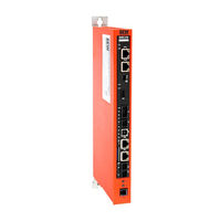
SEW-Eurodrive DHF41B Manual (124 pages)
DeviceNet and PROFIBUS DP-V1 Fieldbus Interfaces
Brand:
SEW-Eurodrive
| Category:
Controller
| Size: 5 MB
Table of Contents
Table of Contents
3
1 General Information
6
How to Use the Documentation
6
Structure of the Safety Notes
6
Rights to Claim under Limited Warranty
7
Exclusion of Liability
7
Copyright
7
2 Safety Notes
8
Other Applicable Documentation
8
Bus Systems
8
Safety Functions
8
Hoist Applications
8
Product Names and Trademarks
8
Waste Disposal
8
3 Introduction
9
Content of the Manual
9
Characteristics
9
Process Data Exchange
9
Parameter Access
9
Monitoring Functions
10
4 Assembly and Installation Notes on the Devicenet Fieldbus
11
Connecting MOVI-PLC® Advanced DHF41B to a Devicenet Network
11
Connecting Devicenet (Connector X30D)
11
Shielding and Routing Bus Cables
12
Bus Termination
12
Setting the DIP Switches
13
Status LED of the DHF41B Option
14
5 Project Planning and Startup on the Devicenet Fieldbus
16
Validity of EDS Files for the DHF41B Option
16
Configuring PLC and Master (Devicenet Scanner)
17
Settings in MOVI-PLC ® Advanced DHF41B
19
Process Data Configuration
19
Status of the Fieldbus Interface
20
Project Planning Examples in Rslogix5000
21
MOVI-PLC ® Advanced DHF41B with 16 Process Data
21
Access to Parameters of MOVI-PLC ® Advanced DHF41B
25
Access to Unit Parameters of Lower-Level Units
30
6 Devicenet Operating Characteristics
31
Process Data Exchange
31
The Common Industrial Protocol (CIP)
34
CIP Object Directory
34
Return Codes of the Parameterization Via Explicit Messages
43
Terms and Definitions
47
7 Error Diagnostics for Operation on the Devicenet Fieldbus
48
Diagnostic Procedures
48
8 Assembly and Installation Notes on the PROFIBUS DP-V1 Fieldbus
50
Connecting MOVI-PLC ® Advanced DHF41B to a PROFIBUS Network
50
Connecting PROFIBUS (Connector X30P)
50
Status LED of the DHF41B Option
52
9 Configuration and Startup on the PROFIBUS DP-V1 Fieldbus
53
Configuring a PROFIBUS DP Master
53
10 PROFIBUS DP-V1 Operating Characteristics
60
Process Data Exchange with MOVI-PLC® Advanced DHF41B
60
PROFIBUS-DP Timeout
62
Settings in MOVI-PLC ® Advanced DFHF41B
62
Status of the PROFINET Fieldbus Interface
63
Parameter Setting Via PROFIBUS-DP
65
Return Codes for Parameter Setting
70
Special Cases
71
11 Functions of PROFIBUS DP-V1
73
Introduction to PROFIBUS DP-V1
73
Class 1 Master (C1 Master)
74
Class 2 Master (C2 Master)
74
Data Sets (DS)
74
DP-V1 Services
75
DP-V1 Alarm Handling
75
Features of SEW Fieldbus Interfaces
76
Structure of the DP-V1 Parameter Channel
77
Parameterization Procedure Via Data Set 47
79
DP-V1 Master Processing Sequence
80
Addressing Connected Inverters
81
MOVILINK ® Parameter Requests
82
Profidrive Parameter Orders
86
Configuring a C1 Master
91
Operating Mode (DP-V1 Mode)
91
Example Program for SIMATIC S7
92
Technical Data of DP-V1 for MOVI-PLC
93
Advanced DHF41B
93
Error Codes of the DP-V1 Services
94
12 Operating MOVITOOLS ® Motionstudio
95
About MOVITOOLS® Motionstudio
95
Tasks
95
Establishing Communication with the Units
95
Executing Functions with the Units
95
First Steps
96
Starting the Software and Creating a Project
96
Establishing Communication and Scanning the Network
96
Communication Mode
97
Overview
97
Selecting Communication Mode (Online or Offline)
98
Communication Via USB (Direct)
99
Connecting the Unit with the PC Using USB Connection Cables
99
Installing the Drivers
100
Configuring USB Communication
100
USB Communication Parameters
102
Communication Via Ethernet
103
Connecting the Unit with the PC Via Ethernet
103
Configuring the Communication Channel Via Ethernet
104
Setting Communication Parameters for SMLP
105
Communication Via PROFIBUS DP/DP-V1
107
Communication Via C2 Master
107
Additionally Required Hardware and Software
108
Parameterize C2 Master with SIMATIC NET
109
Configuring Communication Via PROFIBUS
112
Communication Parameters for PROFIBUS DP/DP-V1
114
Executing Functions with the Units
115
Parameterizing Units in the Parameter Tree
115
Reading/Changing Unit Parameters
115
Starting up the Units (Online)
116
13 Error Diagnostics for Operation on PROFIBUS DP-V1
117
Diagnostic Procedure for PROFIBUS-DP
117
14 Appendix
118
Parameter Access to Lower-Level Units Via Devicenet
118
Parameter Access to Lower-Level Units Via PROFIBUS DP-V1
119
Parameter Access to Lower-Level Units Via Engineering Interfaces
120
Advertisement
Sew Eurodrive DHF41B Manual (92 pages)
Brand:
Sew Eurodrive
| Category:
Controller
| Size: 6 MB
Table of Contents
Table of Contents
3
1 General Information
6
About this Documentation
6
Structure of the Safety Notes
6
Meaning of Signal Words
6
Structure of Section-Related Safety Notes
6
Structure of Embedded Safety Notes
7
Rights to Claim under Limited Warranty
7
Content of the Documentation
7
Exclusion of Liability
8
Other Applicable Documentation
8
Product Names and Trademarks
8
Copyright Notice
8
2 Safety Notes
9
Preliminary Information
9
Use
9
Target Group
9
Designated Use
10
Hoist Applications
10
Functional Safety Technology
10
Bus Systems
10
3 Introduction
11
Content of this Manual
11
Additional Documentation
11
4 Device Structure
12
Overview of Controllers
12
Freely Programmable Controller MOVI-PLC
12
Configurable Application Controller CCU
12
Features
13
Fieldbus Interfaces of the Device Designs
13
Communication Interfaces
13
Engineering
15
System Buses
15
Binary Inputs and Outputs
16
Diagnostic Leds
16
5 Mechanical Installation
17
In the UOH11B/21B Stand-Alone Housing
17
In MOVIDRIVE MDX61B
17
Before You Start
17
Installing and Removing the DH.21/41B Option Card
18
In the MOVIAXIS MXM Master Module
19
6 Electrical Installation
20
Terminal Positions
20
DH.21B/41B Controller
20
DH.21B/41B Controller in the Stand-Alone Housing
21
DH.21B/41B Controller in MOVIDRIVE
22
Mdx61B
22
DH.21B/41B Controller in the MOVIAXIS
22
MXM Master Module
22
DH.21B/41B Controller in MOVITRAC
24
DHF21B/41B Controller
25
DHR21B/41B Controller
26
Terminal Assignment and DIP Switches
27
X24: COM 1 (RS485) Engineering Interface
27
X26: CAN 1 System Bus Interface and Voltage Supply
27
X30-1/X30-2: Ethernet 3/Ethernet 4 Connection
28
X30P: PROFIBUS Connection
29
X30D: Devicenet
31
X31: Digital Inputs and Outputs
33
X32/X33: CAN 2/CAN 1 System Bus Interface
34
X34: COM 1/COM 2 (RS485) Engineering Interface
35
X35: USB Engineering Interface
36
X36: Ethernet 1 System Bus Interface
36
X37: Ethernet 2 Engineering Interface
37
X38: SEW Safety Bus Connection
38
DIP Switch S1 for DH.21B/41B
38
DIP Switches 2 and 2 1 for DHR21B/41B
39
SD Memory Cards
40
SD Memory Card OMH41B-T
40
SD Memory Card OMC41B-T
41
Bootloader Update
42
Shielding and Routing Bus Cables
43
7 Project Planning and Startup with MOVITOOLS Motionstudio
44
About MOVITOOLS Motionstudio
44
Tasks
44
Communication Channels
44
Functions
44
First Steps
45
Starting the Software and Creating a Project
45
Establishing Communication and Scanning the Network
45
Connection Mode
46
Configuring Units
48
Communication Via USB
50
Connecting the Unit with the PC Via USB
50
Configuring the Communication Channel Via USB
51
Communication Via Ethernet
51
Connecting the Device with the PC Via Ethernet
51
Configuring the Communication Channel Via Ethernet
52
Communication Ports Used
54
Startup of the Fieldbus at the DHR21B/41B Controller
54
The Integrated Ethernet Switch
54
TCP/IP Addressing and Subnets
55
Setting the IP Address Parameters Via DCP
58
Setting the IP Address Parameters
58
Executing Functions with the Units
60
Reading or Changing Unit Parameters
60
Starting up Units (Online)
61
Configuring and Starting up Drives
62
Configuration and Startup in the PLC Editor
62
Replacing the Unit
62
8 Operation
63
DH.21B/41B Controller
63
LED "H1/H2" in Stand-Alone Operation
63
LED "L1" (CAN 1 Status)
63
LED "L2" (CAN 2 Status)
64
LED "L3" (IEC Program Status)
64
LED "L4" (Controller Status)
64
LED "L5" (User)
64
Leds "L6", "L7", "L8", "L9" (DIO N/M)
65
Led "L10" (24 V / I/O Ok)
65
DHF21B/41B Controller
65
Leds in PROFIBUS Mode
66
Leds in Devicenet TM Mode
67
DHR21B/41B Controller
69
Leds in PROFINET Mode
69
Leds in Ethernet/Ip and Modbus/Tcp Mode
71
9 Service
73
System Bus CAN 1/CAN 2
73
Disposal
74
10 Technical Data and Dimension Drawings
75
General Technical Data
75
Technical Data of the DH.21B/41B Option Card
76
Technical Data of the DHF21B/41B Option Card
78
Technical Data of the DHR21B/41B Option Card
79
Technical Data of the Stand-Alone Device
79
Port Overview
80
Profinet
80
Ethernet/Ip™, Modbus/Tcp
80
Engineering Interface
81
Dimension Drawings
82
DHE21B/41B Option Card in UOH11B Stand-Alone Housing
82
DHF21B/41B and DHR21B/41B Option Cards in UOH21B Stand-Alone Housing
83
Index
84
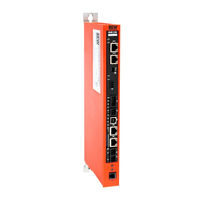
Sew Eurodrive DHF41B Manual (80 pages)
Standard/advanced
Brand:
Sew Eurodrive
| Category:
Controller
| Size: 5 MB
Table of Contents
Table of Contents
3
1 General Information
6
How to Use the Documentation
6
Structure of the Safety Notes
6
Meaning of the Signal Words
6
Structure of Section Safety Notes
6
Structure of Embedded Safety Notes
6
Right to Claim under Warranty
7
Exclusion of Liability
7
Copyright
7
2 Safety Notes
8
Other Applicable Documentation
8
Bus Systems
8
Safety Functions
8
Hoist Applications
8
Disposal
9
3 Introduction
10
General Information
10
Content of this Manual
10
Additional Documentation
10
Overview of Controllers
11
Freely Programmable Motion and Logic Controller (MOVI-PLC ® )
11
Configurable Application Controller (CCU)
11
Controller DH.21B/41B
12
Features
12
Device Types
12
Overview of Communication Interfaces
12
Engineering
13
System Buses CAN 1, CAN 2 and Ethernet 1
14
RS485 Interfaces COM1 and COM2
14
Ethernet 2
14
Binary Inputs and Outputs
14
Diagnostic Leds
14
4 Assembly and Installation Notes
15
Installation Options of DH.21B/41B
15
Installing the DH.21B/41B Option in MOVIDRIVE ® MDX61B
15
Before You Start
15
Basic Procedure for Installing or Removing an Option Card in MOVIDRIVE MDX61B
16
Installing the DH.21B/41B Option in MOVIDRIVE ® MDX61B
17
Installing the DH.21B/41B Option in the MOVIAXIS ® Master Module
17
Functional Description of Terminals X5A / X5B
17
(MOVIAXIS ® Master Module)
17
Installing the DH.21B/41B Option in MOVITRAC ® B / Stand-Alone Unit
19
Description of Terminals and Leds
19
RS485 Interface COM1 Connection (Connector X24)
19
Connecting CAN 1 System Bus/Voltage Supply (X26)
20
LED When Installing in MOVITRAC ® /Stand-Alone Unit
21
Shielding and Routing Bus Cables
22
Installing the DH.21B/41B Option
23
Functional Description of Terminals, DIP Switches and Leds
23
Connecting Binary Inputs and Outputs (X31 Terminal)
24
Connnection to System Bus CAN 2 (X32) / CAN 1 (X33)
25
RS485 Interface Connection (X34)
26
System Bus Ethernet 1 Connection (X36)
27
Ethernet 2 Interface Connection (X37)
27
Leds of the DH.21B/41B Option
27
DIP Switch S1
29
SD Memory Card Types OMH41B-T. and OMC41B-T
30
Installing the DHF21B/41B Option
32
Functional Description of Terminals, DIP Switches and Leds
32
Connecting PROFIBUS (X30P)
33
Leds in PROFIBUS Mode
34
Connecting Devicenet (X30D)
35
Leds in Devicenet Mode
36
Connecting SEW Safety Bus (X38)
38
Installing the DHR21B/41B Option
39
Functional Description of the Terminals, DIP Switches and Leds
39
Connecting the DHR21B/41B Controller to the Ethernet Network
40
Setting DIP Switches 20 and 21
40
The Integrated Ethernet Switch
41
TCP / IP Addressing and Subnets
42
Leds in PROFINET Mode
44
Setting IP Address Parameters Via DCP
45
Leds in Ethernet/Ip and Modbus/Tcp Mode
46
Setting IP Address Parameters
47
Engineering Interfaces of the DH.21B/41B Option
49
5 Project Planning and Startup with MOVITOOLS ® Motionstudio
50
About MOVITOOLS ® Motionstudio
50
Tasks
50
Establishing Communication with Other Units
50
Executing Functions with the Units
50
First Steps
51
Starting the Software and Creating a Project
51
Establishing Communication and Scanning the Network
51
Connection Mode
52
Overview
52
Selecting the Communication Mode (Online or Offline)
53
Communication Via USB
54
Connecting the Unit with the PC Via USB
54
Installing the Driver
55
Configuring USB Communication
56
USB Communication Parameters
57
Communication Via Ethernet
58
Direct Communication
58
Address Editor
59
Configuring the Communication Channel Via Ethernet
62
Setting Communication Parameters for SMLP
64
Communication Parameters for SMLP
65
Communication Ports Used
65
Executing Functions with the Units
66
Parameterizing Units
66
Reading or Changing Unit Parameters
66
Starting up Units (Online)
67
Configuration and Startup of the Drives
68
Configuration and Startup in the PLC Editor
68
Replacing the Unit
68
6 Error Diagnostics
69
Diagnostic Procedure CAN 1/CAN 2 System Bus
69
7 Technical Data and Dimension Drawings
70
General Technical Data
70
DHE21B/41B Option
71
DHF21B/41B Option
73
DHR21B/41B Option
74
Stand-Alone Unit
74
Dimension Drawings for Stand-Alone Unit DH.21B/41B/UOH
75
Dimension Drawing for DHE21B/41B / UOH11B
75
Dimension Drawing for DHF/DHR21B/41B / UOH21B
76
Index
77
Advertisement
Advertisement
Related Products
Sew Eurodrive DHF21B
Sew Eurodrive MOVI-PLC basic DHP11B-T1
Sew Eurodrive MOVI-PLC basic DHP11B-T0
Sew Eurodrive MOVI-PLC basic DHP11B-T2
Sew Eurodrive MOVIDRIVE MOVI-PLC DHP11B
Sew Eurodrive DH 41B Series
Sew Eurodrive DH 21B Series
Sew Eurodrive DHE21B
Sew Eurodrive DHE41B
Sew Eurodrive DHR21B
Sew Eurodrive Categories
Industrial Equipment
DC Drives
Controller
Inverter
Engine
More Sew Eurodrive Manuals
Login
Sign In
OR
Sign in with Facebook
Sign in with Google
Upload manual
Upload from disk
Upload from URL