Seagate Exos X 4006 Series Manuals
Manuals and User Guides for Seagate Exos X 4006 Series. We have 8 Seagate Exos X 4006 Series manuals available for free PDF download: Hardware Installation And Maintenance Manual, Instructions, Getting Started, Replacing

Advertisement

Advertisement


Seagate Exos X 4006 Series Replacing (2 pages)
Replacing a Power Supply Unit in a 5U Enclosure

Seagate Exos X 4006 Series Replacing (2 pages)
Replacing a 2U enclosure drive module in its carrier, Storage Systems and AP Integrated Storage Servers
Brand: Seagate
|
Category: Network Storage Server
|
Size: 0 MB

Seagate Exos X 4006 Series Replacing (2 pages)
Replacing a Power Cooling Module in a 2U Enclosure

Seagate Exos X 4006 Series Replacing (2 pages)
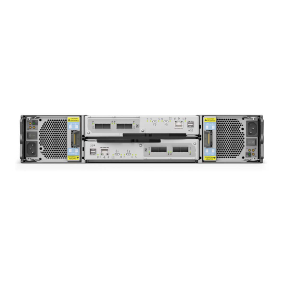
Replacing Controller Module in a 2U Enclosure