Sign In
Upload
Manuals
Brands
SEA TEL Manuals
Transmitter
4012 GX KU-BAND
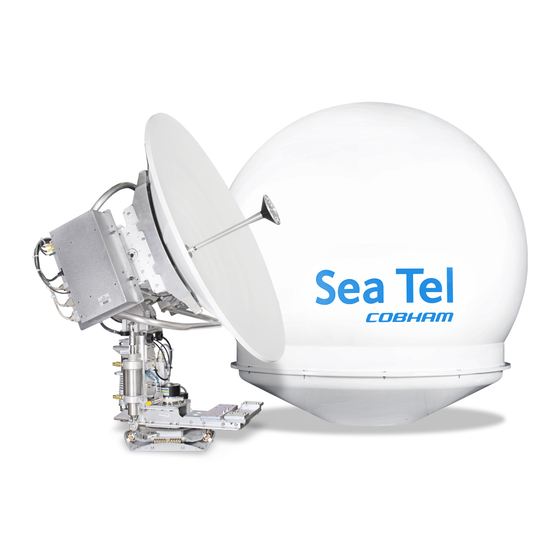
SEA TEL 4012 GX KU-BAND Manuals
Manuals and User Guides for SEA TEL 4012 GX KU-BAND. We have
4
SEA TEL 4012 GX KU-BAND manuals available for free PDF download: Technical Manual, Installation Manual, Operation Manual, Quick Start Manual
Sea Tel 4012 GX KU-BAND Technical Manual (314 pages)
BROADBAND-AT-SEA VSAT ANTENNA SYSTEM
Brand:
Sea Tel
| Category:
Antenna
| Size: 22.4 MB
Table of Contents
Table of Contents
5
1 Gx System Configuration(S)
11
System Cables
11
Other Inputs to the
11
System
11
Simplified Block Diagram of a 4012 Gx System
11
Dual Antenna Configuration
11
Open Antenna-Modem Interface Protocol (Openamip™) Specification
12
Overview
12
Interface Requirements
12
Utilized Openamip TM Commands
12
2 Site Survey
15
Site Selection Aboard the Ship
15
Antenna Shadowing (Blockage) and RF Interference
15
Mounting Foundation
16
Mounting on Deck or Deckhouse
16
ADE Mounting Considerations
16
Sizing of the Support Pedestal
16
Mounting Height
17
Mast Configurations
17
Vertical Masts
18
Raked Masts
18
Girder Masts
18
Truss Mast
19
Safe Access to the Ade
19
Below Decks Equipment Location
19
Cables
19
ADE/BDE Coaxial Cables
20
Antenna Power Cable
20
Air Conditioner Power Cable
20
ACU Power Cable/Outlet
20
Gyro Compass Cable
20
Grounding
21
3 Installation
23
Unpacking and Inspection
23
Assembly Notes and Warnings
23
Installing the Ade
24
Prepare the 61" Radome Assembly
24
Installing the 61" Radome Assembly
25
Grounding the Pedestal
28
Removing the Shipping/Stow Restraints PRIOR to Power-Up
29
Removing the AZ Shipping/Stow Restraint
29
Removing the el Shipping/Stow Restraint
30
Removing the CL Shipping/Stow Restraint
32
Installing the below Decks Equipment
33
General Cautions & Warnings
33
Connecting the below Decks Equipment
33
Connecting the ADE AC Power Cable
33
Connecting the BDE AC Power Cables
33
Media Xchange Point™ (MXP) Connections
33
Other BDE Connections
36
Final Checks
36
Visual/Electrical Inspection
36
Electrical - Double Check Wiring Connections
36
Setup - Media Xchange Point™ (MXP)
36
4 Configuring a Computer for the Mxp
37
5 Setup - Using the Commission Wizard
43
Starting the Commission Wizard
43
Commissioning Wizard
44
6 Setup - Ship's Gyro Compass
51
Setting the Gyro Type
51
7 Setup - Tracking Receiver - Vsat
53
Determining the if Tracking Frequency (Mhz)
53
Sat Skew
53
8 Setup - Home Flag Offset (Ima Software 1.04 or Lesser)
55
You Found a Large Az Trim Value
55
You Observe "Home" Pointing Is LEFT of the Bow-Line (Minus HFO)
56
You Observe "Home" Pointing Is RIGHT of the Bow-Line (Positive HFO)
56
Entering a Large Value as Home Flag Offset
57
Entering a Small Value as AZ TRIM
58
9 Setup - Azimuth Trim (Ima Ver 1.05 or Greater)
59
10 Setup - Blockage & Rf Radiation Hazard Zones
61
10.1. Radiation Hazard and Blockage Mapping
61
Programming Instructions
62
11 Configuring the Satellite Modem Interface
65
Satellite Modem Interface
65
Reflector Setting
66
Modem Type Setting
66
Modem I/O Setting
66
Modem I/O - Custom Settings
67
Quick Reference: Common Modem Lock & Mute Settings
69
12 Setup - Targeting
71
Auto Trim
71
Manually Optimizing Targeting
72
13 Setup - Satellite Configuration
75
Searching Patterns
75
Default "Spiral" (Box) Search Pattern
75
Inclined Orbit Search Pattern
75
Sky Search Pattern
76
Tx Pol Select
76
Band Select
76
X-Pol / Co-Pol Select
76
Selecting/Configuring Your Satellite Configuration
76
14 Quick Start Operation
79
If Satellite Signal Is Found and Network Lock Is Achieved
79
If no Signal Is Found
79
If Satellite Signal Is Found but Network Lock Is NOT Achieved
81
T Otarget a Different Satellite
83
15 Optimizing Cross-Pol Isolation
85
Solation
85
16 Codan Mini-Buc Ethernet M&C Install & Operation
87
Cable Installation
87
Setting up the Ip Address and Subnet Mask in the Computer
87
Communicating with the Codan Mini-BUC Using Codan GUI
88
Issuing Set, Output and View Commands Via Telnet
89
17 Gx Dealer Menus
91
Functional Differences Among the Three Log in Categories
91
System Status
92
Satellite Signal Automatic Search
94
Communication Interfaces
95
System Configuration
100
Reflector Configuration
104
Satellite Configuration
108
Hardware Profile
111
Graphs
115
Cli Commands
119
Position Antenna
120
Test
127
Activity
131
Data Export
134
Admin
139
Configuration
140
Upgrading Your IMA Software (Firmware)
142
Ssl
145
Change Password
146
Faq
147
Help
148
18 Stowing the Antenna
149
18.1. Installing the Stow Restraints
149
Installing the AZ Shipping/Stow Restraint
149
Installing the el Shipping/Stow Restraint
150
Installing the CL Shipping/Stow Restraint
152
18.2. Removing the Shipping/Stow Restraints PRIOR to Power-Up
152
Removing the AZ Shipping/Stow Restraint
152
Removing the el Shipping/Stow Restraint
153
Removing the CL Shipping/Stow Restraint
155
19 Preventive Maintenance - Operator Checks and Inspections
157
19.1. Maintenance Requirements
157
19.1.1. Radome Inspections
157
19.1.2. Cable Inspections
157
19.1.3. Wire-Rope Isolator Inspections
158
19.1.4. Azimuth Drive Component Inspections
158
19.1.5. Home Switch Sensor Inspection
159
19.1.6. Vertical Isolation Inspections
159
19.1.7. Cross-Level Drive Component Inspections
160
19.1.8. Elevation Drive Component Inspections
161
19.1.9. Motor Junction Enclosure Inspections
161
ICU Inspections
161
BUC Inspections
162
Counter-Weight Inspections
162
Dish Perimeter Inspections
162
20 Diagnostics, Fault Isolation & Troubleshooting
163
Power on Self Test (POST)
163
Real Time Clock
163
NAND Test
163
Eeprom
163
I2C 0
163
Processor Serial Port
163
External Serial Port
163
ADC Chip - Power Supplies - Temp Sensor
163
Ethernet PHY Chip
164
CAN Controller
164
RF Serial Interface
164
LNB Voltage
164
I Nservice Test (Ist)
164
Motor Driver Board
164
Polarization Angle Potentiometer Range
164
Receiver
164
Out of Service Test (OOST)
164
Motors (AZ, EL, and CL): Do They Turn
165
Motors (Polang)
165
Motion Platform
165
Motor Brakes
165
Operator Troubleshooting Flow Chart
165
Ima System Led Functions
167
Error Code Color-State Overview
167
Error LED (by States)
168
Initializing LED
169
Power LED
170
Target LED
170
Search LED
170
Tracking LED
171
Looking up the Actual Errors
171
Error Table
172
Icu Led Functions
179
Check/Test - AZ Motor / Encoder
179
Theory of Operation
179
Verify Initialization
180
MDE Status Leds
180
Test the Motor
180
Verify Encoder Feedback
180
Check/Test - el / CL Motor
181
Est - el / Cl Motor
181
Theory of Operation
181
Verify Initialization
181
MDE Status Leds
181
Test the Motor
181
Verify Motor Brake Release
182
Check/Test - Pedestal Error Types
182
Servo Limit (CL, LV and AZ)
182
Stability Limit
182
AZ Reference Error
183
Check/Test - Home Flag Sensor
183
Theory of Operation
183
Troubleshooting
183
Check/Test - MDE
183
Verify Initialization
183
MDE Status Leds
184
Check/Test - Pol Motor
184
Theory of Operation
184
Verify the Range of Motion of the Feed Assembly (4012)
185
Measure Polarity Motor Voltage
187
Check/Test - Pol Pot
187
Theory of Operation
187
Check the Pol Pot Calibration
188
Verify the Resistance of the Pol Pot
189
Calibrate the Pol Pot
190
Check/Test - Pol Encoder
190
Theory of Operation
190
Verify Initialization
190
Verify the Range of Motion of the Feed Assembly (4012)
191
21 Maintenance
193
21.1. Warranty Information
193
21.2. Torque and Loctite Specifications
194
General Maintenance
194
21.3.1. Balancing the Antenna
194
Fine Balance and Monitoring Motor Drive Torque
195
Replacing Components
196
Replace Wire Rope Isolators
196
Replacing the Rubber Bumpers
199
Replacing the Pneumatic Damper
199
Replacing the Flow Control Valves
202
Replacing the Chain Tensioner Spring
204
Replacing the Azimuth Motor
204
Replacing the el Motor
208
Replacing Elevation Drive Belt
209
Replacing the CL Motor
211
Replacing Cross-Level Drive Belt
213
Replacing the Motor Driver Enclosure (MDE)
214
Replacing the Power Ring Assembly
215
Replacing the 2 Channel Rotary Joint
220
Replacing the Integrated Control Unit (ICU)
226
Replacing the MK2 GPS Antenna
227
Field Replacement, Repair & Calibration of the Ku-Band RF Cage
228
Components of the Antenna Assembly
228
Tools Required
229
Removing the RF Cage
230
Feed Tube Replacement
232
Cross-Pol LNB Replacement
234
Co-Pol LNB Replacement
236
Polarity Motor Replacement
238
Polarity Potentiometer Replacement
240
Polarity Encoder Replacement
243
BUC Replacement
245
Reinstalling the RF Cage
247
Replacing the Mxp
252
22 Ku-Ka Upgrade Procedure
253
Ku-Ka Field Upgrade Procedure
253
Tools Required
253
Preparation
253
Removing the Ku-Band RF Equipment
254
Installing the Ka-Band RF Equipment
257
Install the below Decks Equipment
261
Restore AC Power to the below Decks Equipment
261
23 Gx Technical Specifications
263
Above Decks Equipment
263
Below Decks Equipment
270
Regulatory Compliance
272
Cables
273
Antenna L-Band if Coax Cables (Customer Furnished)
273
24 Drawings
275
4012 GX Ku-Band Model Specific Drawings
275
Advertisement
SEA TEL 4012 GX KU-BAND Installation Manual (103 pages)
BROADBAND-AT-SEA VSAT ANTENNA SYSTEM
Brand:
SEA TEL
| Category:
Antenna
| Size: 12.77 MB
Table of Contents
Table of Contents
9
1 Gx System Configuration(S)
13
System Cables
13
Other Inputs to the 1.3. Simplified Block Diagram of a 4012 Gx System
13
Dual Antenna Configuration
13
Open Antenna-Modem Interface Protocol (Openamip™) Specification
14
Overview
14
Interface Requirements
14
Utilized Openamip TM Commands
14
2 Site Survey
17
Site Selection Aboard the Ship
17
Antenna Shadowing (Blockage) and RF Interference
17
Mounting Foundation
18
Mounting on Deck or Deckhouse
18
ADE Mounting Considerations
18
Sizing of the Support Pedestal
18
Mounting Height
19
Mast Configurations
19
Vertical Masts
20
Raked Masts
20
Girder Masts
20
Truss Mast
21
Safe Access to the Ade
21
Below Decks Equipment Location
21
Cables
21
ADE/BDE Coaxial Cables
22
Antenna Power Cable
22
Air Conditioner Power Cable
22
ACU Power Cable/Outlet
22
Gyro Compass Cable
22
Grounding
23
3 Installation
25
Unpacking and Inspection
25
Assembly Notes and Warnings
25
Installing the Ade
26
Prepare the 61" Radome Assembly
26
Installing the 61" Radome Assembly
27
Grounding the Pedestal
30
Removing the Shipping/Stow Restraints PRIOR to Power-Up
31
Removing the AZ Shipping/Stow Restraint
31
Removing the el Shipping/Stow Restraint
32
Removing the CL Shipping/Stow Restraint
34
Installing the below Decks Equipment
35
General Cautions & Warnings
35
Connecting the below Decks Equipment
35
Connecting the ADE AC Power Cable
35
Connecting the BDE AC Power Cables
35
Media Xchange Point™ (MXP) Connections
35
Other BDE Connections
36
Final Checks
36
Visual/Electrical Inspection
36
Electrical - Double Check Wiring Connections
36
Setup - Media Xchange Point™ (MXP)
37
4 Configuring a Computer for the Mxp
39
5 Setup - Ship's Gyro Compass
45
Setting the Gyro Type
45
If There Is no Ships Gyro Compass
45
6 Setup - Tracking Receiver - Vsat
47
Determining the if Tracking Frequency (Mhz)
47
Sat Skew
47
7 Setup - Home Flag Offset
49
You Found a Large Az Trim Value
49
You Observe "Home" Pointing Is LEFT of the Bow-Line
50
You Observe "Home" Pointing Is RIGHT of the Bow-Line
50
Entering a Large Value as Home Flag Offset
50
Entering a Small Value as AZ TRIM
51
8 Setup - Blockage Zones
53
9 Setup - Targeting
55
Auto Trim
55
Manually Optimizing Targeting
56
10 Setup - Satellite Configuration
59
11 Quick Start Operation
61
If Satellite Signal Is Found and Network Lock Is Achieved
61
If no Signal Is Found
61
If Satellite Signal Is Found but Network Lock Is NOT Achieved
63
T Otarget a Different Satellite
65
12 Optimizing Cross-Pol Isolation
67
Solation
67
13 Gx Technical Specifications
69
4012 Ku-Band Antenna Reflector
69
4012 Ku-Band RF Cage
69
Ku-Band Linear TXRX Feed Assy
69
TX Radio Package
69
SMW Quad Band LNB
70
Integrated Control Unit (Icu)
71
Motor Driver Enclosure (Mde)
71
Stabilized Antenna Pedestal Assembly
72
GPS (Integrated on Pedestal)
73
Radome Assembly , 61
74
4012 Environmental Specifications (Ade)
74
Environmental Conditions (ADE)
74
Chemically Active Substances
74
Mechanical Conditions
75
Transit Conditions
75
Media Xchange Point
75
Ship's Terminal Interface (MXP)
75
MXP Box Rear Panel Connections
76
Integrated SCPC Receiver
76
Control Interface
77
SW1 Local Band Select Output
77
SW2 Blockage/ TX Mute Output
77
NMEA Interface
77
Icu/Pedestal Power Supply
78
BUC Power Supply
78
Bde Environmental Conditions
78
System Weight (Ade)
78
Power Requirements
78
Regulatory Compliance
78
Cables
79
Antenna L-Band if Coax Cables (Customer Furnished)
79
14 Drawings
81
4012 GX Ku-Band Model Specific Drawings
81
Sea Tel 4012 GX KU-BAND Operation Manual (54 pages)
BROADBAND-AT-SEA TRANSMIT / RECEIVE SYSTEM
Brand:
Sea Tel
| Category:
Transmitter
| Size: 3.51 MB
Table of Contents
Table of Contents
5
1 Introduction
7
2 Quick Start Operation
9
If Satellite Signal Is Found and Network Lock Is Achieved
9
If no Signal Is Found
10
If Satellite Signal Is Found but Network Lock Is NOT Achieved
11
To Target a Different Satellite
13
Basic Description of the Front Panel Status Leds
14
3 Gx User Menus
17
User Login
17
System Status
18
Satellite Signal Automatic Search
20
Satellite Configuration
21
Graphs
22
Position Antenna
26
Activity
33
Data Export
37
Change Password
42
Faq
43
Help
44
4 Stowing the Antenna
47
Installing the Stow Restraints
47
Installing the AZ Shipping/Stow Restraint
47
Installing the el Shipping/Stow Restraint
48
Installing the CL Shipping/Stow Restraint
50
Removing the Shipping/Stow Restraints PRIOR to Power-Up
50
Removing the AZ Shipping/Stow Restraint
50
Removing the el Shipping/Stow Restraint
51
Removing the CL Shipping/Stow Restraint
53
Advertisement
Sea Tel 4012 GX KU-BAND Quick Start Manual (2 pages)
Brand:
Sea Tel
| Category:
Antenna
| Size: 1.48 MB
Advertisement
Related Products
Sea Tel 4012
SEA TEL 4006-23 IN A 60" RADOME
Sea Tel 4009-33
Sea Tel Cobham 4009-91 MK3
Sea Tel 4009-9 BROADBAND-AT-SEA
SEA TEL Categories
Antenna
Control Unit
Power Supply
Recording Equipment
Air Conditioner
More SEA TEL Manuals
Login
Sign In
OR
Sign in with Facebook
Sign in with Google
Upload manual
Upload from disk
Upload from URL