Sign In
Upload
Manuals
Brands
Schweitzer Engineering Laboratories Manuals
Relays
SEL-387-5
Schweitzer Engineering Laboratories SEL-387-5 Manuals
Manuals and User Guides for Schweitzer Engineering Laboratories SEL-387-5. We have
2
Schweitzer Engineering Laboratories SEL-387-5 manuals available for free PDF download: Instruction Manual
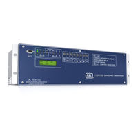
Schweitzer Engineering Laboratories SEL-387-5 Instruction Manual (568 pages)
Current Differential Overcurrent Relay Data Recorder
Brand:
Schweitzer Engineering Laboratories
| Category:
Relays
| Size: 4.84 MB
Table of Contents
Table of Contents
3
List of Tables
11
Preface
17
Manual Overview
17
Conventions
19
Safety Information
20
Section 1: Introduction and Specifications
21
Overview
21
Relay Functions
22
Current Differential Protection
22
Figure 1.1 Functional Overview
22
Restricted Earth Fault Protection
23
Thermal Protection (SEL-387-6 Relay)
23
Overcurrent Protection
23
Through-Fault Event Monitor (SEL-387-5 and SEL-387-6)
24
Programmable Optoisolated Inputs and Output Contacts
24
Application Ideas
25
Figure 1.2 Transformer and Overcurrent Protection
25
Figure 1.3 Transformer and Low-Voltage Bus Protection
25
Figure 1.4 Bus and Feeder Protection
26
Figure 1.5 Unit Differential Protection
26
Model Options
27
SEL-387-0 Relay
27
SEL-387 Relay
27
SEL-387-6 Relay
27
Conventional Terminal Blocks
27
Plug-In Connectors (Connectorized ® )
27
Specifications
28
Section 2: Installation
31
Overview
31
Relay Mounting
32
Rack Mount
32
Panel Mount
32
Dimensions and Cutout
33
Figure 2.1 Relay Dimensions for Rack-Mount and Panel-Mount Models
33
Figure 2.2 Front-Panel Drawings-Models 0387X0Xxxh and 0387X1Xxxh
34
Figure 2.3 Front-Panel Drawings-Models 0387X0Xxx3 and 0387X1Xxx3
35
Rear-Panel Connections
36
Terminal Block
36
Connectorized
36
Figure 2.4 Rear-Panel Drawings-Models 0387X0Xxxxx and 0387X1Xxxx2
37
Figure 2.5 Rear-Panel Drawings-Models 0387X1Xxxx4 and 0387X1Xxxx6
38
Figure 2.6 Rear-Panel Drawings-Models 0387Xyxxxx6 and 0387Xyxxxx2
39
Connections
40
Figure 2.7 Standard Independent Output Contact Representation
41
Table 2.1 SEL-387 Communication Cable Numbers
42
Typical AC/DC Connections
43
Figure 2.8 Example AC Connections (Three-Winding Transformer)
43
Figure 2.9 Example DC Connections (Basic Version)
44
Circuit Board Configuration
45
Accessing the Relay Circuit Boards
45
Main Board
46
Table 2.2 SEL-387 Second ALARM Contact Jumper Position
46
Additional Interface Board
48
Figure 2.10 Main Board Jumpers, Connections, and Battery Locations
50
Figure 2.11 Interface Board 2 Component Layout (Conventional Terminal Block)
51
Figure 2.12 Interface Board 4 Component Layout (Conventional Terminal Block)
52
Figure 2.13 Interface Board 6 Component Layout (Conventional Terminal Block)
53
Figure 2.14 Interface Board 2 Component Layout (Connectorized)
54
Figure 2.15 Interface Board 6 Component Layout (Connectorized)
55
Section 3: Differential, Restricted Earth Fault, Thermal, and Overcurrent Elements
57
Overview
57
Differential Element
58
Application Description
58
Operating Characteristic
58
Figure 3.1 Percentage Restraint Differential Characteristic
58
Figure 3.2 Winding 1 Compensated Currents
59
Figure 3.3 Differential Element (87-1) Quantities (SEL-387-0)
60
Figure 3.4 Differential Element (87-1) Quantities (All but SEL-387-0)
61
Figure 3.5 Differential Element Decision Logic
62
Figure 3.6 Differential Element Harmonic Blocking Logic
64
Figure 3.7 Differential Element (87BL1) Blocking Logic (SEL-387-0)
65
Figure 3.8 Differential Element (87BL1) Blocking Logic (All but SEL-387-0)
65
Setting Descriptions
66
Figure 3.9 DC Blocking (DCBL1) Logic (All but SEL-387-0)
66
Temperature Measurement (SEL-387-5 and SEL-387-6 Relays)
72
Setting Descriptions
72
Setting Calculation
73
Table 3.1 the Complete List of Compensation Matrices (M = 1 to 12)
75
Figure 3.10 Winding Connections, Phase Shifts, and Compensation Direction
76
Figure 3.11 Example 1 for Wnctc Selection
78
Figure 3.12 Example 2 for Wnctc Selection
80
Application Guideline
86
Restricted Earth Fault Element
88
Application Description
88
Operating Characteristic
88
Figure 3.13 REF Enable/Block Logic
89
Figure 3.14 REF Directional Element
89
Figure 3.15 REF Protection Output (Extremely Inverse-Time O/C)
90
Setting Descriptions
91
Setting Calculation
91
Figure 3.16 REF Function, 32IOP Setting Guide
92
Thermal Element (SEL-387-6 Relay)
94
Application Description
94
Operating Characteristic
94
Figure 3.17 Thermal Element Logic
94
Figure 3.18 Top-Oil and Hot-Spot Temperatures
95
Setting Descriptions
100
Table 3.2 Examples of Cooling Stages and MVA Ratings
102
Table 3.3 Default Transformer Constants
106
Application Guideline, Using the SEL-2030 to Send Temperature Data to the SEL-387-6
108
Figure 3.19 Example System Block Diagram
109
Overcurrent Element
110
Application Description
110
Operating Characteristic
110
Table 3.4 Overcurrent Element Summary
110
Figure 3.20 50Pn1 Phase Definite-Time O/C Element, Torque Controlled
111
Figure 3.21 50Pn2 Phase Instantaneous O/C Element, Torque Controlled
111
Figure 3.22 50Pn3 and 50Pn4 Phase Instantaneous O/C Element, Nontorque Controlled
112
Figure 3.23 51Pn Phase Inverse-Time O/C Element, Torque Controlled
112
Figure 3.24 50Qn1 and 50Nn1 Sequence Definite-Time O/C Element, Torque Controlled
113
Figure 3.25 50Qn2 and 50Nn2 Sequence Instantaneous O/C Element, Torque Controlled
113
Figure 3.26 51Qn and 51Nn Sequence Inverse-Time O/C Element, Torque Controlled
114
Figure 3.27 Combined Overcurrent Example
116
Figure 3.28 51PC1 and 51NC1 Combined Inverse-Time O/C Elements
117
Setting Descriptions
121
Figure 3.29 51PC2 and 51NC2 Combined Inverse-Time O/C Elements
121
Application Guidelines
123
Time-Overcurrent Curves
128
Standard Inverse-Time Characteristic Curves
128
Table 3.5 Equations Associated with U.S. Curves
128
Table 3.6 Equations Associated with IEC Curves
128
Figure 3.30 U. S. Moderately Inverse Curve: U1
129
Figure 3.31 U.S. Inverse Curve: U2
130
Figure 3.32 U.S. very Inverse Curve: U3
131
Figure 3.33 U.S. Extremely Inverse Curve: U4
132
Figure 3.34 U.S. Short-Time Inverse Curve: U5
133
Figure 3.35 I.E.C. Class a Curve (Standard Inverse): C1
134
Figure 3.36 I.E.C. Class B Curve (very Inverse): C2
135
Figure 3.37 I.E.C. Class C Curve (Extremely Inverse): C3
136
Figure 3.38 I.E.C Long-Time Inverse Curve: C4
137
Figure 3.39 I.E.C. Short-Time Inverse Curve: C5
138
Section 4: Control Logic
139
Overview
139
Optoisolated Inputs
140
Input Functions
140
Factory Settings Examples
140
Local Control Switches (All but SEL-387-0 Relay)
141
Remote Control Switches
142
Remote Bit Application
142
Remote Bit States Not Retained When Power Is Lost
142
Remote Bit States Retained When Settings Changed or Active Setting Group Changed
142
Figure 4.1 Remote Control Switches Drive Remote Bits RB1 through RB16
142
Multiple Setting Groups
144
Active Setting Group Indication
144
Selecting the Active Setting Group
144
Operation of SEL OGIC Control Equation Settings SS1 through SS6
144
Operation of Serial Port GROUP Command and Front-Panel {GROUP} Pushbutton
145
Relay Disabled Momentarily During Active Setting Group Change
145
Active Setting Group Switching Example
145
Table 4.1 Definitions for Active Setting Group
145
Table 4.2 Active Setting Group Switching Input Logic
146
Figure 4.2 Rotating Selector Switch for Active Setting Group Selection
146
CHSG Relay Word Bit Asserts During Setting Group Changes
147
Table 4.3 SEL OGIC Control Equation Settings for Rotating Selector Switch
147
Active Setting Group Retained for Power Loss, Settings Change
148
SEL OGIC Control Equation Sets (1 through 3) Variables
149
Variables/Timers
150
Latch Control Switches
150
Figure 4.4 Traditional Latching Relay
151
Output Contacts
152
Factory Settings Example
152
Operation of Output Contacts for Different Output Contact Types
152
Rotating Default Display
154
LED Targeting Logic
155
Figure 4.6 SEL-387 Front-Panel Leds
155
Table 4.6 LED Assignments
155
LED 1 - en - Relay Enabled
156
LED 2 - TRIP - Relay Trip
156
LED 10 - B - B-Phase Involved in the Fault (Programmable LEDB)
157
LED 11 - C - C-Phase Involved in the Fault (Programmable LEDC)
157
LED 12 - N - Residual Overcurrent Element Trip
157
LED 4 - 87-1 - Differential Element
157
LED 5 - 87-2 - Differential Element
157
LED 6 - 87-3 - Differential Element
157
LED 9 - a - A-Phase Involved in the Fault (Programmable LEDA)
157
LED 13 - W1 - Winding 1 Overcurrent Element Operation
158
Trip and Close Logic
159
Trip Logic
159
Figure 4.7 SEL-387 Trip Logic (TRIP1)
159
Close Logic
160
Figure 4.8 SEL-387 Close Logic (CLS1)
161
SEL OGIC Control Equations
163
SEL OGIC Control Equations Fundamental Description
163
SEL OGIC Control Equation Logical Operators
163
Table 4.7 SEL OGIC Control Equation Operators
163
Ways of Setting SEL OGIC Control Equation Relay Settings
164
Limitations of SEL OGIC Control Equations
165
Relay Word Bits
167
Table 4.9 SEL-387 Relay Word Bits and Locations
167
Table 4.10 Relay Word Bit Definitions
168
Table 4.11 Relay Word Bits Sorted Alphabetically
180
Section 5: Metering and Monitoring
193
Overview
193
Metering Functions
194
Instantaneous Phase Current Meter Function (METER Command)
194
Demand Ammeter Function (METER D Command)
195
Phasor Current Metering Function (METER SEC Command)
197
Demand Reset Functions (MET RD and MET RP Commands)
198
Harmonic Metering Function (MET H Command)
199
Figure 5.1 SEL-387 Demand Ammeter Functions and Commands
199
Temperature Measurement (SEL-387-5 and SEL-387-6 Relays)
200
Station DC Battery Monitor
201
Instantaneous Battery Voltage Values
201
Undervoltage and Overvoltage Alarms
201
Figure 5.2 Station DC Battery Monitor Alarm Logic
201
Figure 5.3 Undervoltage and Overvoltage Warning and Alarm Regions
201
Detection of Voltage Dips in Event Reports
202
Breaker Monitor
203
Breaker Monitor Description and Initiation Setting
203
Breaker Wear Curve Description and Settings
204
Figure 5.4 Trip Bus Sensing with Relay Input
204
Figure 5.5 Breaker Contact Wear Curve
204
Breaker Wear Example
206
Breaker Monitor Report Function (BRE Command)
206
Thermal Monitor (SEL-387-6 Relay)
208
Thermal Monitor Report Function (the Command)
208
Thermal Event Report Quantities
208
Table 5.1 Thermal Element Conditions
209
Thermal Event Report Function (the N Command)
210
Thermal Profile Data Report Function (the H and the D Commands)
210
Retrieving Thermal Data Reports
212
Thermal Monitor Reset Functions (the R, the C, and the P Commands)
212
Table 5.2 Using the the Command to Access Data Reports
212
Through-Fault Event Monitor
214
Through-Fault Event Monitor Settings
214
Table 5.3 Through-Fault Event Monitor Settings
214
Figure 5.6 Distribution Feeder Faults Expose Transformer Bank to through Faults
214
Through-Fault Calculation
215
Figure 5.7 Through-Fault Triggering, Duration, and Maximum Current
215
Through-Fault Alarm
216
Through-Fault Event (TFE) Serial Port Command
216
Figure 5.8 Cumulative I 2 T Alarm (Relay Word Bit ISQTAL)
216
Deriving Cumulative I T Values for Preloading
217
Magnitude Limits on Through-Fault Event Data
218
Status Monitor
219
Status Monitor Report Function (STATUS Command)
219
Channel Offset
219
Power Supply
219
Temperature
219
Ram
220
Flash ROM
220
Analog to Digital Converter
220
Critical RAM
220
Eeprom
220
Interface Boards
220
Self-Test Alarm Limits
220
Table 5.4 Self-Test Alarm Limits
220
Section 6: Setting the Relay
221
Overview
221
Table 6.1 Serial Port SET Commands
221
Settings Changes Via the Front Panel
222
Settings Changes Via the Serial Port
223
Table 6.2 SET Command Editing Keystrokes
223
Additional Relay Settings
224
Relay (RID) and Terminal (TID) Identification
224
Demand Ammeter Settings (DATC, PDEM, QDEM, NDEM)
224
Input and Output Assignments
224
Trip and Close Logic
225
System Frequency (NFREQ) and Phase Rotation (PHROT)
227
Miscellaneous (DATE_F, SCROLD, FP_TO, TGR)
227
DC Battery Monitor (DC1P-DC4P)
228
Breaker Monitor
228
Analog Input Labels
228
Setting Group Selection
228
Front-Panel Targeting, Displays, and Control
228
Sequential Events Recorder
229
Communications Ports
229
Default Settings
230
Default Settings (5
230
Default Settings (1
231
Settings Sheets
234
Section7: Serial Port Communications and Commands
311
Settings Sheets Example
311
Overview
311
Establish Communication
312
Software
312
Port Identification
312
Cables
312
Table 7.1 Serial Port Pin Definitions
312
Figure 7.1 SEL-387 Serial Port Connectors
312
Table 7.2 SEL-387 Communication Cable Numbers
313
SEL-387 to Computer
314
SEL-387 to Modem
315
To SEL Communications Processor
316
Table 7.3 Serial Communications Port Pin Function Definitions
316
Communications Protocol
317
Hardware Protocol
317
Software Protocol
317
SEL ASCII Protocol Details
320
Automatic Messages
320
Access Levels
322
Figure 7.2 Access Level Relationship
324
Command Definitions
325
Table 7.4 MET Command Choices
332
Table 7.5 Editing Keys for SET Commands
337
Table 7.6 Settings for each Communication Port
338
Table 7.7 TFE Command Choices
347
Table 7.8 the Command Choices
348
Alarm Conditions
349
Main Board Jumpers
349
Table 7.9 Commands with Alarm Conditions
349
Table 7.10 Main Board Jumpers
349
SEL-387 Relay Command Summary
351
Section 8: Front-Panel Interface
359
Front-Panel Operation
359
Time-Out
359
Figure 8.1 SEL-387 Front-Panel User Interface
359
Displays
360
Target Leds
360
Password Access
360
Pushbuttons
362
Primary Function Review
362
Figure 8.2 Local Control Switch Configured as an ON/OFF Switch
369
Figure 8.3 Local Control Switch Configured as an OFF/MOMENTARY Switch
369
Figure 8.4 Local Control Switch Configured as an ON/OFF/MOMENTARY Switch
369
Table 8.1 Correspondence between Local Control Switch Positions and Label Settings
370
Table 8.2 Correspondence between Local Control Switch Types and Required Label Settings
370
Secondary Function Review
373
Pushbutton/Serial Port Equivalents
374
Table 8.3 Front-Panel Pushbutton Serial Port Equivalents
374
Programmable LEDA, LEDB, LEDC
375
Rotating Default Display
376
Traditional Indicating Panel Lights Replaced with Rotating Default Display
376
General Operation of Rotating Default Display Settings
376
Dynamic Display
377
Table 8.4 Dynamic Display Same-Line Overcurrent Elements
379
Table 8.5 Dynamic Display Mnemonics
381
Scroll Lock Control of Front-Panel LCD
382
Figures of Selected Front-Panel Menu Structures
384
Figure 8.5 METER Menu and Display Structure
384
Figure 8.6 EVENTS Display Structure
385
Figure 8.7 OTHER / BKR Menu and Display Structure
386
Figure 8.8 SET Menu and Display Structure
387
Section 9: Event Reports and SER
389
Overview
389
Standard 15-, 30-, or 60-Cycle Event Reports
390
Event Report Length (Settings LER and PRE)
390
Standard Event Report Triggering
390
Standard Event Report Summary
391
Table 9.1 Event Types
392
Figure 9.1 Example Event Summary
392
Retrieving Full-Length Standard Event Reports
393
Table 9.2 Winding Event Report Current Columns
394
Figure 9.2 Example Winding Event Report
394
Table 9.3 Winding Event Report Output and Input Columns
395
Table 9.4 Digital Event Report Column Description
396
Figure 9.3 Example Digital Event Report
396
Table 9.5 Differential Event Report Current Columns
399
Figure 9.4 Example Differential Event Report
399
Table 9.6 Differential Event Report Element Columns
400
Table 9.7 Raw Winding Event Report Current Columns
403
Figure 9.5 Example Raw Winding Event Report
403
Compressed ASCII Event Reports
404
Table 9.8 Raw Winding Event Report Outputs and Inputs
404
Figure 9.6 Derivation of Event Report Current Values and RMS Current Values from Sampled Current Waveform
405
Figure 9.7 Derivation of Phasor RMS Current Values from Event Report Current Values
406
Sequential Events Recorder (SER) Event Report
408
SER Event Report Row Triggering and ALIAS Settings
408
Figure 9.8 Example SER Event Report
408
Making SER Event Report Trigger Settings
409
Retrieving SER Event Report Rows
409
Table 9.9 Different SER Event Report Responses
409
Clearing SER Event Report Buffer
410
Section 10: Testing and Troubleshooting
411
Overview
411
Testing Methods and Tools
412
Test Features Provided by the Relay
412
Table 10.1 Features to Use to Test the Relay
412
Low-Level Test Interface
413
Test Methods
413
Figure 10.1 Low-Level Test Interface
413
Acceptance Testing
415
Equipment Required
415
Initial Checkout
415
Power Supply
416
Serial Communications
416
Figure 10.2 Relay Part Number and Hardware Identification Sticker
416
Outputs
419
Inputs
420
Metering
420
Figure 10.3 Test Connections for Balanced Load with Three-Phase Current Sources
421
Figure 10.4 Test Connections for Balanced Load with Two-Phase Current Sources
421
Winding Overcurrent
422
Table 10.2 Instantaneous Overcurrent Elements and Corresponding Settings
423
Figure 10.5 Test Connections for Two Single Current Test Sources
423
Table 10.3 Time-Delayed Overcurrent Elements and Corresponding Settings
425
Combined Overcurrent Elements
427
Restricted Earth Fault (REF) Function
430
Differential
432
Figure 10.6 Percentage Restraint Differential Characteristic
432
Table 10.4 Connection Compensation Factor
433
Figure 10.7 Test Connections for Parallel Current Sources
439
Time-Code Input (IRIG-B)
442
Thermal Element
443
Commissioning Testing
445
Maintenance Testing
446
Relay Troubleshooting
447
Inspection Procedure
447
Troubleshooting Procedure
447
Relay Calibration
452
Factory Assistance
452
SEL-387-0, -5, -6 Relay Commissioning Test Worksheet
453
System Information
453
Settings Check
454
Connection Check
455
Magnitude, Angle, and Phase Rotation Check
455
Appendix A: Firmware and Manual Versions
457
Firmware
457
Determining the Firmware Version in Your Relay
457
Table A.1 Firmware Revision History-SEL-387-0 Relay
457
Table A.2 Firmware Revision History-SEL-387-5 Relay
459
Table A.3 Firmware Revision History-SEL-387-6 Relay
462
Table A.4 Settings Change History-SEL-387-5
464
Table A.5 Settings Change History-SEL-387-6
464
Table A.6 Manual Revision History-SEL-387-0, -5, -6
465
Appendix B: SEL-300 Series Relays Firmware Upgrade Instructions
469
Table A.7 Manual Revision History-SEL-387-0 Relay
470
Table A.8 Manual Revision History-SEL-387-5, -6 Relay
473
Optional Equipment
477
Required Equipment
477
Upgrade Procedure
478
Figure B.1 Establishing a Connection
479
Figure B.2 Determining the Computer Serial Port
479
Figure B.3 Determining Communications Parameters for the Computer
480
Figure B.4 Setting Terminal Emulation
480
Failure to Connect
481
Figure B.5 Terminal Emulation Startup Prompt
481
Figure B.6 Correcting the Port Setting
481
Figure B.7 Correcting the Communications Parameters
482
Figure B.8 Preparing Hyperterminal for ID Command Display
483
Figure B.9 List of Commands Available in SEL BOOT
484
Figure B.10 Matching Computer to Relay Parameters
485
Figure B.11 Example Receive File Dialog Box
486
Figure B.12 Example Filename Identifying Old Firmware Version
486
Figure B.13 Downloading Old Firmware
486
Figure B.14 Selecting New Firmware to Send to the Relay
488
Figure B.15 Transferring New Firmware to the Relay
488
Table B.1 Troubleshooting New Firmware Upload
489
Figure B.16 Preparing Hyperterminal for ID Command Display
492
Appendix Csel Distributed Port Switch Protocol (LMD)
495
Overview
495
Settings
495
Operation
496
Appendix D: Configuration, Fast Meter, and Fast Operate Commands
497
Overview
497
Message Lists
498
Table D.1 Binary Message List
498
Table D.2 ASCII Configuration Message List
498
Message Definitions
499
A5C0 Request
499
A5C1 Request
499
Table D.3 A5CO Relay Definition Block
499
Table D.4 A5C1 Fast Meter Configuration Block
499
A5D1 Request
502
A5B9 Fast Meter Status Acknowledge Message
503
A5C2/A5CE Demand/Peak Demand
503
Table D.5 A5D1 Fast Meter Data Block
503
Table D.6 A5C2/A5C3 Demand/Peak Demand Fast Meter Configuration Messages
503
A5D2/A5D3 Demand/Peak Demand
506
A5CE Fast Operate
506
Table D.7 A5D2/A5D3 Demand/Peak Demand Fast Meter Message
506
Table D.8 A5CE Fast Operate Configuration Block
506
A5E0 Fast Operate
507
A5E3 Fast Operate
508
A5CD Fast Operate
508
A5ED Fast Operate
508
Table D.9 A5E0 Fast Operate Remote Bit Control
508
Table D.10 A5E3 Fast Operate Breaker Control
508
Table D.11 A5CD Fast Operate Reset Definition Block
508
Table D.12 A5ED Fast Operate Reset Command
508
A546 Temperature
509
ID Command
509
DNA Command
509
Table D.13 A546 Temperature Data Block (SEL-387-5 and SEL-387-6)
509
BNA Command
510
SNS Message
510
Appendix E: Compressed ASCII Commands
511
Overview
511
Table E.1 SEL-387 Compressed ASCII Commands
511
CASCII Command-General Format
512
SEL-387-0, -5 Relay
514
CASCII Command
514
CBREAKER Command
515
CEVENT Command
515
CEVENT Winding Report (Default)
516
CEVENT Differential Report
517
CHISTORY Command
517
CSTATUS Command
517
CTARGET Command
518
SEL-387-6 Relay
519
CASCII Command
519
CBREAKER Command
521
CEVENT Command
521
CEVENT Winding Report (Default)
522
CEVENT Differential Report
523
CHISTORY Command
523
CSTATUS Command
523
CTARGET Command
524
CTH Thermal Report Command
524
CTH Event Report
524
CTH Daily Profile Data Report
525
CTH Hourly Profile Data Report
526
CTH Temperature Input Data Report
526
Appendix F Unsolicited SER Protocol
529
Overview
529
Recommended Message Usage
530
Functions and Function Codes
531
0X01 - Function Code: Enable Unsolicited Data Transfer
531
0X02 - Function Code: Disable Unsolicited Data Transfer
532
0X18 - Function: Unsolicited Sequence-Of-Events Response
532
Acknowledge Message
533
Examples
534
Notes
535
Appendix G: Distributed Network Protocol
537
Overview
537
Configuration
538
Table G.1 Data Needed to Configure a Port for DNP
538
Data-Link Operation
540
Data Access Method
541
Table G.2 Data Access Methods
541
DNP3 Documentation
542
Device Profile
542
Table G.3 SEL-387 DNP3 Device Profile
542
Object Table
543
Table G.4 SEL-387 Relay DNP Object Table
543
Data Map
546
Table G.5 SEL-387 Relay-Wye/Delta DNP Data Map
546
Table G.6 SEL-387-5 and SEL-387-6 Relays Continuation of Wye/Delta DNP Data Map
550
Table G.7 SEL-387-5, -6 Relay Binary Input Lookup Table
552
Relay Summary Event Data
554
Point Remapping
555
Introduction
555
Advertisement
Schweitzer Engineering Laboratories SEL-387-5 Instruction Manual (532 pages)
CURRENT DIFFERENTIAL RELAY; OVERCURRENT RELAY; DATA RECORDER
Brand:
Schweitzer Engineering Laboratories
| Category:
Relays
| Size: 6.2 MB
Table of Contents
Qvwdqwdqhrxv'Hilqlwh7Lph 2Yhufxuuhqw
23
Manual Trip
349
Display Reset
358
Event Data
359
5Hod\ 'Hilqlwlrq %Orfn
464
Dvw 0Hwhu &Rqiljxudwlrq %Orfn
464
' )Dvw 0Hwhu 'Dwd %Orfn
467
Dvw 0Hwhu 6Wdwxv $Fnqrzohgjh 0Hvvdjh
467
Dvw 2Shudwh &Rqiljxudwlrq %Orfn
470
Dvw 2Shudwh 5Hprwh %Lw &Rqwuro
471
Advertisement
Related Products
Schweitzer Engineering Laboratories SEL-387-0
Schweitzer Engineering Laboratories SEL-387-6
Schweitzer Engineering Laboratories SEL-387E
Schweitzer Engineering Laboratories SEL-321-3
Schweitzer Engineering Laboratories SEL-352-1
Schweitzer Engineering Laboratories SEL-321-1
Schweitzer Engineering Laboratories SEL-351
Schweitzer Engineering Laboratories SEL-351-7
Schweitzer Engineering Laboratories SEL-351-2
Schweitzer Engineering Laboratories SEL-351-0
Schweitzer Engineering Laboratories Categories
Relays
Computer Hardware
Transceiver
Protection Device
Measuring Instruments
More Schweitzer Engineering Laboratories Manuals
Login
Sign In
OR
Sign in with Facebook
Sign in with Google
Upload manual
Upload from disk
Upload from URL