Sign In
Upload
Manuals
Brands
Schweitzer Engineering Laboratories Manuals
Relays
SEL-351
Schweitzer Engineering Laboratories SEL-351 Manuals
Manuals and User Guides for Schweitzer Engineering Laboratories SEL-351. We have
1
Schweitzer Engineering Laboratories SEL-351 manual available for free PDF download: Instruction Manual
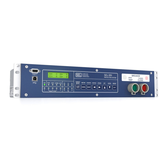
Schweitzer Engineering Laboratories SEL-351 Instruction Manual (614 pages)
DIRECTIONAL OVERCURRENT RELAY RECLOSING RELAY FAULT LOCATOR
Brand:
Schweitzer Engineering Laboratories
| Category:
Relays
| Size: 6 MB
Table of Contents
Table of Contents
15
Section 1: Introduction and Specifications
17
SEL-351 Relay Models
17
Table 1.1: SEL-351 Relay Models
17
Instruction Manual Sections Overview
19
Table 1.2: SEL-351 Firmware Versions
19
Applications
23
Figure 1.1: SEL-351 Relays Applied Throughout the Power System
23
Hardware Connection Features
24
Figure 1.2: SEL-351 Relay Inputs, Outputs, and Communications Ports (Model 0351Xt)
24
Figure 1.3: SEL-351 Relay Inputs, Outputs, and Communications Ports
25
0351X1, and 0351Xy; Models 0351X1 and 0351Xy Have an Extra I/O Board
25
Figure 1.4: SEL-351 Relay Extra I/O Board
26
Main Board Shown in Figure 1.3)
26
Communications Connections
28
Figure 1.6: SEL-351 Relay Communications Connections Examples
28
General Specifications
29
Instantaneous/Definite-Time Overcurrent Elements
33
Processing Specifications
33
Relay Element Pickup Ranges and Accuracies
33
Synchronism-Check Elements
34
Time-Overcurrent Elements
34
Under- and Overvoltage Elements
34
Metering Accuracy
35
Substation Battery Voltage Monitor
35
Under- and Overfrequency Elements
35
Power Element Accuracy
36
Section 2: Installation
37
Table of Contents
37
Section 2: Installation
41
Relay Mounting
41
Rear-Panel Connection Diagrams
42
Making Rear-Panel Connections
47
Improvements in Connectorized
47
Models 0351Xt and 0351Xy (Plug-In Connectors)
47
Relays (Plug-In Connectors) Result in
47
Required Equipment and General Connection Information
47
Wiring Harness
48
Chassis Ground
49
Models 0351X0 and 0351X1
49
Models 0351X0 and 0351X1 (Screw-Terminal Blocks)
49
Models 0351Xt and 0351Xy
49
High-Current Interrupting Output Contacts
50
Model 0351Xt
50
Models 0351X0 and 0351X1
50
Models 0351Xt and 0351Xy
50
Output Contacts
50
Power Supply
50
Standard Output Contacts
50
Model 0351X0
51
Models 0351X1 and 0351Xy
51
Standard Output Contacts
51
Current Transformer Inputs
52
High-Current Interrupting Output Contacts
52
Models 0351Xt and 0351Xy
52
Optoisolated Inputs
52
Delta-Connected Voltages
53
Models 0351X0 and 0351X1
53
Models 0351Xt and 0351Xy
53
Potential Transformer Inputs
53
Wye-Connected Voltages
53
Delta-Connected Voltages
54
Models 0351X0 and 0351X1
54
Serial Ports
54
Wye-Connected Voltages
54
IRIG-B Time-Code Input
56
Example
57
Circuit Board Connections
65
Accessing the Relay Circuit Boards
65
Extra Alarm" Output Contact Control Jumper
70
Output Contact Jumpers
70
Section 3: Overcurrent, Voltage, Synchronism Check, Frequency, and Power Elements/Section 3: Overcurrent, Voltage, Synchronism Check, Frequency, and Power Elements
75
Instantaneous/Definite-Time Overcurrent Elements
79
Phase Instantaneous/Definite-Time Overcurrent Elements
79
Accuracy
79
Settings Ranges
79
Pickup Operation
81
Directional Control Option
83
Torque Control
83
Combined Single-Phase Instantaneous Overcurrent Elements
84
Pickup and Reset Time Curves
85
Phase-To-Phase Instantaneous Overcurrent Elements
86
Accuracy
86
Pickup and Reset Time Curves
86
Pickup Operation
86
Setting Range
86
Neutral Ground Instantaneous/Definite-Time Overcurrent Elements
86
Accuracy
89
Pickup and Reset Time Curves
89
Settings Ranges
89
Residual Ground Instantaneous/Definite-Time Overcurrent Elements
90
Accuracy
91
Pickup and Reset Time Curves
91
Settings Ranges
91
Negative-Sequence Instantaneous/Definite-Time Overcurrent Elements
92
Accuracy
92
Pickup and Reset Time Curves
92
Settings Ranges
92
Section 3: Overcurrent, Voltage, Synchronism Check, Frequency, and Power Elements
79
Time-Overcurrent Elements
94
Phase Time-Overcurrent Elements
94
Settings Ranges (51PT Element Example)
95
Accuracy
96
Logic Outputs (51PT Element Example)
96
Torque Control Switch Closed
97
Torque Control Switch Open
97
Torque Control Switch Operation (51PT Element Example)
97
Control of Logic Point TCP
98
Directional Control Option
98
Torque Control
98
Reset Timing Details (51PT Element Example)
99
Setting 51PRS = y
99
Operation of Single-Phase Time-Overcurrent Elements (51AT, 51BT, 51CT)
100
Setting 51PRS = N
100
Neutral Ground Time-Overcurrent Element
102
Accuracy
103
Settings Ranges
103
Residual Ground Time-Overcurrent Element
103
Settings Ranges
104
Accuracy
105
Negative-Sequence Time-Overcurrent Element
105
Accuracy
106
Settings Ranges
106
Voltage Elements
107
Voltage Values
107
Voltage Element Settings
107
Accuracy
114
Voltage Element Operation
114
Overvoltage Element Operation Example
115
Undervoltage Element Operation Example
115
Voltage Elements Used in POTT Logic
115
Synchronism Check Elements
116
Voltage Input VS Connected with a Different CT Configuration than the Reference Phase or Beyond a Delta-Wye Transformer
116
Synchronism Check Elements Settings
117
Setting SYNCP
118
Accuracy
118
Synchronism Check Elements Voltage Inputs
120
AB for Delta) and
121
System Frequencies Determined from Voltages V
121
System Rotation Can Affect Setting SYNCP
121
Synchronism Check Elements Operation
122
Block Synchronism Check Conditions
122
Other Uses for Voltage Window Elements
122
Voltage Window
122
Angle Difference Calculator
123
Slip Frequency Calculator
123
Angle Difference Example
124
P and V S Are "Slipping")
124
S Are "Slipping
124
Voltages V P and V S
124
P and V Are "Slipping" and Setting TCLOSD ≠ 0.00
127
Synchronism Check Applications for Automatic Reclosing and Manual Closing
129
Frequency Elements
129
Frequency Element Settings
129
Accuracy
131
Create Over- and Underfrequency Elements
131
Overfrequency Element
132
Underfrequency Element
132
Frequency Element Operation
132
Overfrequency Element Operation
132
Frequency Element Voltage Control
133
Instruction Manual
133
Other Uses for Undervoltage Element 27B81
133
Underfrequency Element Operation
133
Section 4: Loss-Of-Potential, Load Encroachment, and Directional Element Logic/Section 4: Loss-Of-Potential, Load Encroachment, and Directional Element Logic
143
Loss-Of-Potential Logic
147
Setting ELOP = y or Y1
148
Setting ELOP = y
148
Setting ELOP = N
148
Section 4: Loss-Of-Potential, Load Encroachment, and Directional Element Logic
147
Load-Encroachment Logic
149
Settings Ranges
150
Load-Encroachment Setting Example
150
Convert Maximum Loads to Equivalent Secondary Impedances
151
Convert Power Factors to Equivalent Load Angles
151
Apply Load-Encroachment Logic to a Phase Time-Overcurrent
152
Use SEL-321 Relay Application Guide for the SEL-351 Relay
153
Directional Control for Neutral Ground and Residual Ground Overcurrent Elements
153
Internal Enables
155
Best Choice Ground Directional Logic
155
Directional Elements
155
Directional Element Routing
156
Loss-Of-Potential
156
Direction Forward/Reverse Logic
156
Internal Enables
164
Directional Elements
165
Directional Element Routing
165
Loss-Of-Potential
165
Direction Forward/Reverse Logic
166
Directional Control Settings
172
Settings Made Automatically
172
Settings
173
DIR1 - Level 1 Overcurrent Element Direction Setting
173
DIR2 - Level 2 Overcurrent Element Direction Setting
173
DIR3 - Level 3 Overcurrent Element Direction Setting
173
DIR4 - Level 4 Overcurrent Element Direction Setting
173
ORDER - Ground Directional Element Priority Setting
174
50P32P - Phase Directional Element Three-Phase Current Pickup
175
Z2F - Forward Directional Z2 Threshold
175
Z2R - Reverse Directional Z2 Threshold
175
50QFP - Forward Directional Negative-Sequence Current Pickup
176
50QRP - Reverse Directional Negative-Sequence Current Pickup
176
Z2F and Z2R Set Automatically
176
50QFP and 50QRP Set Automatically
177
A2 - Positive-Sequence Current Restraint Factor, I
177
A2 Set Automatically
177
K2 - Zero-Sequence Current Restraint Factor, I
177
50GFP - Forward Directional Residual Ground Current Pickup
178
50GRP - Reverse Directional Residual Ground Current Pickup
178
K2 Set Automatically
178
50GFP and 50GRP Set Automatically
179
A0 - Positive-Sequence Current Restraint Factor, I
179
A0 Set Automatically
179
Z0F - Forward Directional Z0 Threshold
180
Z0F and Z0R Set Automatically
180
Z0R - Reverse Directional Z0 Threshold
180
E32IV - SEL OGIC Control Equation Enable
180
Directional Control Provided by Torque Control Settings
181
Section 5: Trip and Target Logic
183
Section 5: Trip and Target Logic
187
Trip Logic
187
Set Trip
189
Unlatch Trip
190
Other Applications for the Target Reset Function
191
Factory Settings Example (Using Setting TR)
191
Set Trip
191
Unlatch Trip
192
Additional Settings Examples
192
Unlatch Trip with 52A Circuit Breaker Auxiliary Contact
192
Unlatch Trip with 52B Circuit Breaker Auxiliary Contact
192
Program an Output Contact for Tripping
193
Switch-Onto-Fault (SOTF) Trip Logic
193
Three-Pole Open Logic
194
Determining Three-Pole Open Condition Without Circuit Breaker Auxiliary Contact
195
Circuit Breaker Operated Switch-Onto-Fault Logic
195
Close Bus Operated Switch-Onto-Fault Logic
195
Switch-Onto-Fault Logic Output (SOTFE)
196
Switch-Onto-Fault Trip Logic Trip Setting (TRSOTF)
196
Enable Setting ECOMM
197
Trip Setting TRCOMM
198
Trip Settings TRSOTF and TR
198
Trip Setting DTT
199
Use Existing SEL-321 Relay Application Guides for the SEL-351 Relay
199
Optoisolated Input Settings Differences between the SEL-321 and SEL-351 Relays
199
Trip Settings Differences between the SEL-321 and SEL-351 Relays
200
Permissive Overreaching Transfer Trip (POTT) Logic
200
Use Existing SEL-321 Relay POTT Application Guide for the SEL-351 Relay
200
External Inputs
200
PT1 - Received Permissive Trip Signal(S)
201
Timer Settings
201
Z3RBD - Zone (Level) 3 Reverse Block Delay
201
EBLKD - Echo Block Delay
202
EDURD - Echo Duration
202
ETDPU - Echo Time Delay Pickup
202
Logic Outputs
202
ECTT - Echo Conversion to Trip
202
EKEY - Echo Key Permissive Trip
202
KEY - Key Permissive Trip
202
Z3RB - Zone (Level) 3 Reverse Block
202
Variations for Permissive Underreaching Transfer Trip (PUTT) Scheme
204
Date Code 20001006 Trip and Target Logic
205
Directional Comparison Unblocking (DCUB) Logic
205
Use Existing SEL-321 Relay DCUB Application Guide for the SEL-351 Relay
206
External Inputs
206
LOG1, LOG2 - Loss-Of-Guard Signal(S)
206
PT1, PT2 - Received Permissive Trip Signal(S)
206
Timer Settings
207
GARD1D - Guard-Present Delay
207
UBDURD - DCUB Disable Delay
207
UBEND - DCUB Duration Delay
207
Logic Outputs
207
UBB1, UBB2 - Unblocking Block Output(S)
207
PTRX1, PTRX2 - Permissive Trip Receive Outputs
209
Installation Variations
209
Directional Comparison Blocking (DCB) Logic
210
Use Existing SEL-321 Relay DCB Application Guide for the SEL-351 Relay
210
External Inputs
210
BT - Received Block Trip Signal(S)
211
Timer Settings
211
67P2SD, 67N2SD, 67G2SD, 67Q2SD - Level 2 Short Delay
211
BTXD - Block Trip Receive Extension
211
Z3XD - Zone (Level) 3 Reverse Dropout Extension
211
Z3XPU - Zone (Level) 3 Reverse Pickup Time Delay
211
Logic Outputs
211
BTX - Block Trip Extension
212
DSTRT - Directional Carrier Start
212
NSTRT - Nondirectional Carrier Start
212
STOP - Stop Carrier
212
Installation Variations
213
Front-Panel Target Leds
215
Additional Target LED Information
216
Another Application for the COMM Target LED
216
COMM Target LED
216
INST Target LED
216
TRIP Target LED
216
50 Target LED
217
A, B, and C Target Leds
217
FAULT TYPE Target Leds
217
G Target LED
217
SOTF Target LED
217
79 Target Leds
218
N Target LED
218
Target Reset/Lamp Test Front-Panel Pushbutton
218
Other Applications for the Target Reset Function
218
Section 6: Close and Reclose Logic
221
Close Logic
223
Set Close
224
Unlatch Close
225
Factory Settings Example
225
Set Close
226
Unlatch Close
226
Defeat the Close Logic
226
Circuit Breaker Status
226
Program an Output Contact for Closing
227
Settings and General Operation
230
For most Applications (Top of Figure 6.2)
230
For a Few, Unique Applications (Bottom of Figure 6.2 and Figure 6.3)
230
Set Reclose Supervision Logic (Bottom of Figure 6.2)
231
Unlatch Reclose Supervision Logic (Bottom of Figure 6.2)
231
Factory Settings Example
232
Other Setting Considerations for SEL-351(1) and SEL-351(2) Relays
233
SEL-351(1) Relay
233
Additional Settings Example 2
234
Section 6: Close and Reclose Logic
223
Reclosing Relay
234
Reclosing Relay States and General Operation
235
Lockout State
236
Reclosing Relay States and Settings/Setting Group Changes
237
Defeat the Reclosing Relay
237
Close Logic Can Still Operate When the Reclosing Relay Is Defeated
238
Reclosing Relay Timer Settings
238
Open Interval Timers
238
Determination of Number of Reclosures (Last Shot)
239
Observe Shot Counter Operation
240
Reset Timer
240
Monitoring Open Interval and Reset Timing
241
Reclosing Relay Shot Counter
241
Reclosing Relay SEL OGIC Control Equation Settings Overview
242
Reclose Initiate and Reclose Initiate Supervision Settings (79RI and 79RIS, Respectively)
242
Factory Settings Example
242
Additional Settings Example
243
Other Settings Considerations
244
Drive-To-Lockout and Drive-To-Last Shot Settings (79DTL and 79DLS, Respectively)
244
Factory Settings Example
244
Additional Settings Example 2
246
Other Settings Considerations
246
Skip Shot and Stall Open Interval Timing Settings (79SKP and 79STL, Respectively)
246
Additional Settings Example 1
247
Factory Settings Example
247
Additional Settings Example 2
248
Additional Settings Example 3
249
Other Settings Considerations
249
Block Reset Timing Setting (79BRS)
249
Factory Settings Example
249
Additional Settings Example 1
250
Sequence Coordination Setting (79SEQ)
250
Additional Settings Example 1
251
Factory Settings Example
251
Additional Settings Example 2
253
Reclose Supervision Setting (79CLS)
254
Section 7: Inputs, Outputs, Timers, and Other Control Logic/Section 7: Inputs, Outputs, Timers, and Other Control Logic
255
Optoisolated Inputs
259
Input Debounce Timers
261
Input Functions
262
Factory Settings Examples
262
Input IN1
262
Input IN2
263
Details on the Remote Control Switch MOMENTARY Position
264
Section 7: Inputs, Outputs, Timers, and Other Control Logic
259
Local Control Switches
264
Local Control Switch Types
265
OFF/MOMENTARY Switch
265
ON/OFF Switch
265
ON/OFF/MOMENTARY Switch
266
Factory Settings Examples
267
Additional Local Control Switch Application Ideas
268
Local Control Switch States Retained
268
Power Loss
268
Settings Change or Active Setting Group Change
269
Remote Control Switches
269
Remote Bit Application Ideas
270
Remote Bit States Not Retained When Power Is Lost
270
Remote Bit States Retained When Settings Changed or Active Setting Group Changed
270
Details on the Remote Control Switch MOMENTARY Position
270
Latch Control Switch Application Ideas
272
Reclosing Relay Enable/Disable Setting Example
272
Feedback Control
273
Use a Remote Bit Instead to Enable/Disable the Reclosing Relay
275
Latch Control Switch States Retained
276
Power Loss
276
Settings Change or Active Setting Group Change
276
Reset Latch Bits for Active Setting Group Change
276
Note: Make Latch Control Switch Settings with Care
277
Multiple Setting Groups
279
Active Setting Group Indication
279
Selecting the Active Setting Group
279
Ogic
280
Operation of Serial Port GROUP Command and Front-Panel GROUP Pushbutton
280
Relay Disabled Momentarily During Active Setting Group Change
281
Active Setting Group Switching Example 1
281
Start out in Setting Group 1
283
Switch Back to Setting Group 1
283
Switch to Setting Group 4
283
Selector Switch Now Rests on Position REMOTE
286
Active Setting Group Retained
287
Power Loss
287
Settings Change
287
Note: Make Active Setting Group Switching Settings with Care
288
Sel Ogic
288
Factory Settings Example
290
Additional Settings Example 2
290
Timers Reset When Power Is Lost, Settings Are Changed, or Active Setting Group Is Changed
291
Output Contacts
292
Factory Settings Example
292
Operation of Output Contacts for Different Output Contact Types
292
Output Contacts OUT1 through OUT11 (Model 0351Xt Example)
292
ALARM Output Contact
293
Rotating Default Display
296
Traditional Indicating Panel Lights
297
Circuit Breaker Status Indication
297
Reclosing Relay Status Indication
297
Traditional Indicating Panel Lights Replaced with Rotating Default Display
297
General Operation of Rotating Default Display Settings
298
Factory Settings Examples
298
Reclosing Relay Status Indication
298
Circuit Breaker Status Indication
299
Reclosing Relay Disabled
299
Reclosing Relay Enabled
299
Circuit Breaker Closed
300
Circuit Breaker Open
300
Additional Settings Examples
300
Display Only One Message
300
Circuit Breaker Open
301
Continually Display a Message
301
Active Setting Group Switching Considerations
302
Reclosing Relay Disabled
302
Reclosing Relay Enabled
302
Setting Group 1 Is the Active Setting Group
302
Switch to Setting Group 4 as the Active Setting Group
303
Additional Rotating Default Display Example
303
Section 8: Breaker Monitor, Metering, and Load Profile Functions/Section 8: Breaker Monitor, Metering, and Load Profile Functions
305
Breaker Monitor
307
Breaker Monitor Setting Example
310
Breaker Maintenance Curve Details
310
Bkmon
312
Operation of SEL OGIC ® Control Equation Breaker Monitor Initiation Setting
312
Breaker Monitor Operation Example
313
0% to 10% Breaker Wear
313
10% to 25% Breaker Wear
313
25% to 50% Breaker Wear
313
50% to 100% Breaker Wear
313
Breaker Monitor Output
318
Example Applications
318
View or Reset Breaker Monitor Information
318
Via Serial Port
318
Via Front Panel
319
Determination of Relay Initiated Trips and Externally Initiated Trips
319
Additional Example
319
Factory Default Setting Example
319
Introduction
307
Section 8: Breaker Monitor, Metering, and Load Profile Functions
307
Station DC Battery Monitor
320
DC Under- and Overvoltage Elements
321
Create Desired Logic for DC Under- and Overvoltage Alarming
321
DCLO < DCHI (Top of Figure 8.10)
322
DCLO > DCHI (Bottom of Figure 8.10)
323
Output Contact Type Considerations ("A" or "B")
323
Additional Application
323
View Station DC Battery Voltage
324
Via Front Panel
324
Via Serial Port
324
Analyze Station DC Battery Voltage
324
Station DC Battery Voltage Dips During Circuit Breaker Tripping
324
Station DC Battery Voltage Dips Anytime
325
Station DC Battery Voltage Dips During Circuit Breaker Closing
325
Operation of Station DC Battery Monitor When AC Voltage Is Powering the Relay
325
Demand Metering
326
Comparison of Thermal and Rolling Demand Meters
326
Rolling Demand Meter Response (EDEM = ROL)
328
Thermal Demand Meter Response (EDEM = THM)
328
Time = 0 Minutes
329
Time = 5 Minutes
329
Time = 10 Minutes
330
Time = 15 Minutes
330
Demand Meter Settings
330
Demand Current Logic Output Application - Raise Pickup for Unbalance Current
332
Residual Ground Demand Current below Pickup GDEMP
333
Residual Ground Demand Current Goes above Pickup GDEMP
333
Residual Ground Demand Current Goes below Pickup GDEMP Again
333
View or Reset Demand Metering Information
334
Via Front Panel
334
Via Serial Port
334
Demand Metering Updating and Storage
334
Energy Metering
334
View or Reset Energy Metering Information
334
Via Front Panel
335
Energy Metering Updating and Storage
335
Maximum/Minimum Metering
335
View or Reset Maximum/Minimum Metering Information
335
Via Serial Port
335
Maximum/Minimum Metering Updating and Storage
335
Clearing the Load Profile Buffer
339
Section 9: Setting the Relay
341
Introduction
343
Section 9: Setting the Relay
343
Settings Changes Via the Front Panel
343
Settings Changes Via the Serial Port
343
Time-Overcurrent Curves
345
Relay Word Bits (Used in SEL OGIC ® Control Equations)
349
Settings Explanations
377
Identifier Labels
377
Current Transformer Ratios
378
Line Settings
378
Delta-Connected Voltages
379
Enable Settings
379
Other System Parameters
379
Settings Sheets
379
Section 10: Serial Port Communications and Commands/Section 10: Serial Port Communications and Commands
405
Introduction
407
Section 10: Serial Port Communications and Commands
407
Port Connector and Communications Cables
408
Irig-B
408
SEL-351 to Computer
410
SEL-351 to Modem
410
SEL-351 to SEL-PRTU
411
To SEL-2020, SEL-2030, or SEL-2100
411
SEL-351 to SEL-DTA2
411
Communications Protocol
412
Hardware Protocol
412
Software Protocols
412
SEL ASCII Protocol
413
Distributed Network Protocol (DNP) V3.00
414
Mirrored Bits
414
SEL Compressed ASCII Protocol
414
SEL Distributed Port Switch Protocol (LMD)
414
Serial Port Automatic Messages
414
Serial Port Access Levels
415
Access Level 0
415
Access Level 1
416
Access Level B
416
Access Level 2
417
Command Summary
417
Command Explanations
419
Access Level 0 Commands
419
ACC, BAC, and 2AC Commands (Go to Access Level 1, B, or 2)
419
Password Requirements and Default Passwords
419
Access Level Attempt (Password Not Required)
420
Access Level Attempt (Password Required)
420
Access Level 1 Commands
421
BRE Command (Breaker Monitor Data)
421
COMM Command (Communication Data - Available in Firmware Versions 1, 2, 3, and 4)
422
DAT Command (View/Change Date)
423
EVE Command (Event Reports)
423
GRO Command (Display Active Setting Group Number)
423
HIS Command (Event Summaries/History)
424
IRI Command (Synchronize to IRIG-B Time Code)
425
LDP Command (Load Profile Report - Available in Firmware Versions 1, 2, 3 and 4)
426
MET Command (Metering Data)
426
MET K - Instantaneous Metering
426
MET D - Demand Metering
427
MET E - Energy Metering
428
MET M - Maximum/Minimum Metering
429
QUI Command (Quit Access Level)
430
SER Command (Sequential Events Recorder Report)
430
SHO Command (Show/View Settings)
430
SSI Command (Voltage Sag/Swell/Interruption Report - Available in Firmware Versions 3 and 4)
434
STA Command (Relay Self-Test Status)
434
STA Command Row and Column Definitions
435
TAR Command (Display Relay Element Status)
436
TIM Command (View/Change Time)
437
TRI Command (Trigger Event Report)
438
Access Level B Commands
438
BRE N Command (Preload/Reset Breaker Wear)
438
CLO Command (Close Breaker)
439
GRO N Command (Change Active Setting Group)
440
OPE Command (Open Breaker)
440
PUL Command (Pulse Output Contact)
441
Access Level 2 Commands
442
CON Command (Control Remote Bit)
442
COP M N Command (Copy Setting Group)
442
LOO Command (Loop Back - Available in Firmware Versions 1, 2, 3, and 4)
443
PAS Command (View/Change Passwords)
443
SET Command (Change Settings)
444
VER Command (Show Relay Configuration and Firmware Version)
444
Sel-351 Relay Command Summary
445
Section 11: Front-Panel Interface
449
Front-Panel Pushbutton Operation
451
Overview
451
Primary Functions
451
Front-Panel Password Security
452
Secondary Functions
453
Introduction
451
Section 11: Front-Panel Interface
451
Functions Unique to the Front-Panel Interface
455
Reclosing Relay Shot Counter Screen
455
Reclosing Relay Shot Counter Screen Operation (with Factory Settings)
456
Local Control
457
View Local Control (with Factory Settings)
458
Operate Local Control (with Factory Settings)
459
Local Control State Retained When Relay Deenergized
460
Rotating Default Display
461
Additional Rotating Default Display Example
464
Section 12: Standard Event Reports, Sag/Swell/ Interruption Report, and Ser/Section 12: Standard Event Reports, Sag/Swell/ Interruption Report, and Ser
465
Interruption Report, and Ser
467
Introduction
467
Section 12: Standard Event Reports, Sag/Swell/ Interruption Report, and Ser
467
Standard 15/30-Cycle Event Reports
467
Event Report Length (Settings LER and PRE)
467
Relay Word Bit TRIP
468
Standard Event Report Triggering
468
TRI (Trigger Event Report) and PUL (Pulse Output Contact) Commands
469
Event Type
470
Standard Event Report Summary
470
Currents
471
Fault Location
471
Targets
471
Retrieving Full-Length Standard Event Reports
472
Compressed ASCII Event Reports
473
Filtered and Unfiltered Event Reports
473
Clearing Standard Event Report Buffer
474
Current, Voltage, and Frequency Columns
474
Standard Event Report Column Definitions
474
Output, Input, and Protection and Control Columns
475
Sequential Events Recorder (SER) Report
489
Make Sequential Events Recorder (SER) Settings with Care
490
Making SER Trigger Settings
490
Retrieving SER Reports
490
Clearing SER Report
492
Example Standard 15-Cycle Event Report
492
Example Sequential Events Recorder (SER) Report
500
SSI Triggering and Recording
502
Retrieving SSI Reports
503
Clearing SSI Report
504
Example Sag/Swell/Interruption (SSI) Report
504
Section 13: Testing and Troubleshooting
505
Introduction
507
Section 13: Testing and Troubleshooting
507
Testing Philosophy
507
Acceptance Testing
507
Commissioning Testing
507
Testing Methods and Tools
509
Test Features Provided by the Relay
509
Low-Level Test Interface
509
Delta-Connected Voltages
510
Sensitive Earth Fault (SEF) Channel in (0.05 a Nominal)
510
Test Methods
510
Testing Via Front-Panel Indicators
511
Testing Via Output Contacts
511
Testing Via Sequential Events Recorder
511
Relay Self-Tests
512
Relay Troubleshooting
514
Inspection Procedure
514
Troubleshooting Procedure
515
All Front-Panel Leds Dark
515
Cannot See Characters on Relay LCD Screen
515
Relay Does Not Respond to Commands from Device Connected to Serial Port
515
Relay Does Not Respond to Faults
515
Relay Calibration
515
Factory Assistance
516
Table of Contents
517
Appendix A: Firmware Versions
521
Determining the Firmware Version in Your Relay
521
Firmware Revision History Table
522
Appendix B: Firmware Upgrade Instructions
529
Firmware (Flash) Upgrade Instructions
529
Required Equipment
529
Upgrade Procedure
529
Appendix C: Sel Distributed Port Switch Protocol
535
Settings
535
Operation
535
Appendix D: Configuration, Fast Meter, and Fast Operate Commands
537
Introduction
537
Message Lists
537
ASCII Configuration Message List
537
Binary Message List
537
Message Definitions
538
A5C0 Relay Definition Block
538
A5D1 Fast Meter Data Block
541
A5C2/A5C3 Demand/Peak Demand Fast Meter Configuration Messages
543
A5B9 Fast Meter Status Acknowledge Message
545
A5CE Fast Operate Configuration Block
545
A5D2/A5D3 Demand/Peak Demand Fast Meter Message
545
A5E0 Fast Operate Remote Bit Control
546
A5E3 Fast Operate Breaker Control
547
DNA Message
548
BNA Message
549
Appendix E: Compressed Ascii Commands
551
CASCII Command - General Format
551
CASCII Command - SEL-351
552
CSTATUS Command - SEL-351
557
CHISTORY Command - SEL-351
558
CEVENT Command - SEL-351
559
Appendix F: Setting Negative-Sequence Overcurrent Elements
563
Coordination Example
564
Apply the Feeder Relay Negative-Sequence Overcurrent Element
566
Traditional Phase Coordination
566
Convert "Equivalent" Phase Overcurrent Element Settings to Negative-Sequence Overcurrent Element Settings (Guideline 4
567
Negative-Sequence Overcurrent Element Applied at a Distribution Bus (Guideline 5
568
Ground Coordination Concerns
569
Other Negative-Sequence Overcurrent Element References
569
Appendix G: Setting Sel Ogic ® Control Equations
571
Relay Word Bits
571
Phase Time-Overcurrent Element 51PT Pickup Indication
571
Relay Word Bit Operation Example - Phase Time-Overcurrent Element 51PT
571
Other Relay Word Bits
572
Phase Time-Overcurrent Element 51PT Reset Indication
572
Phase Time-Overcurrent Element 51PT Time-Out Indication
572
Relay Word Bit Application Examples - Phase Time-Overcurrent Element 51PT
572
SEL OGIC Control Equation Operators
573
Example of NOT Operator ! Applied to Single Element
574
SEL OGIC Control Equation NOT Operator
574
SEL OGIC Control Equation Parentheses Operator
574
Example of NOT Operator ! Applied to Multiple Elements (Within Parentheses
575
SEL OGIC Control Equation Rising Edge Operator
575
SEL OGIC Control Equation Falling Edge Operator
577
SEL OGIC Control Equation Operation Example - Tripping
577
Set an Output Contact for Tripping
579
SEL OGIC Control Equation Limitations
580
Appendix H: Distributed Network Protocol (Dnp) V3.00
585
Overview
585
Data-Link Operation
586
Data Access Method
586
Device Profile
587
Object Table
590
Data Map
593
Point Remapping
597
Other Versions
598
Appendix I: Mirrored Bits
603
To 4
603
Overview
603
Operation
603
Message Decoding and Integrity Checks
603
Message Transmission
603
Synchronization
604
Channel Monitoring
605
Loop-Back Testing
605
Mirrored Bits
609
Settings
612
Advertisement
Advertisement
Related Products
Schweitzer Engineering Laboratories SEL-351S
Schweitzer Engineering Laboratories SEL-351-1
Schweitzer Engineering Laboratories SEL-351-0
Schweitzer Engineering Laboratories SEL-351-3
Schweitzer Engineering Laboratories SEL-351-2
Schweitzer Engineering Laboratories SEL-351-4
Schweitzer Engineering Laboratories SEL-351-5
Schweitzer Engineering Laboratories SEL-351-6
Schweitzer Engineering Laboratories SEL-351-7
Schweitzer Engineering Laboratories SEL-351R
Schweitzer Engineering Laboratories Categories
Relays
Computer Hardware
Transceiver
Protection Device
Measuring Instruments
More Schweitzer Engineering Laboratories Manuals
Login
Sign In
OR
Sign in with Facebook
Sign in with Google
Upload manual
Upload from disk
Upload from URL