Sign In
Upload
Manuals
Brands
Schweitzer Engineering Laboratories Manuals
Relays
SEL-387E
Schweitzer Engineering Laboratories SEL-387E Manuals
Manuals and User Guides for Schweitzer Engineering Laboratories SEL-387E. We have
1
Schweitzer Engineering Laboratories SEL-387E manual available for free PDF download: Instruction Manual
Schweitzer Engineering Laboratories SEL-387E Instruction Manual (578 pages)
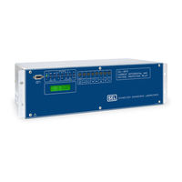
Current Differential and Voltage Protection Relay
Brand:
Schweitzer Engineering Laboratories
| Category:
Relays
| Size: 9 MB
Table of Contents
Table of Contents
5
Introduction and Specifications
7
Introduction
7
Instruction Manual Overview
7
Relay Functions
8
Current Differential Protection
8
Overcurrent Protection
9
Overvoltage and Undervoltage Protection
9
Restricted Earth Fault Protection
9
Volts-Per-Hertz Protection
9
Frequency Protection
10
Programmable Optoisolated Inputs and Output Contacts
10
Through-Fault Event Monitor
10
Model Options
10
Conventional Terminal Blocks
10
Plug-In Connectors (Connectorized )
10
Specifications
11
General
11
Differential Element
14
Metering Accuracy
14
Station DC Battery Monitor
14
Harmonic Element
15
Instantaneous/Definite-Time Overcurrent Elements (Winding)
15
Time Overcurrent Elements (Winding and Combined Current)
15
Frequency Element
16
Over-/Undervoltage Elements
16
Volts/Hertz Element
16
Table 2.1: Sel-387E Relay Communication Cable Numbers/Table 2.2: Sel-387E Relay Second Alarm Contact Jumper Position
17
Section 2: Installation
19
Installation
19
Panel Mount
19
Rack Mount
19
Relay Mounting
19
Dimensions and Cutout
20
Connections
23
Connectorized
23
Rear-Panel Connections
23
Terminal Block
23
Frame Ground
28
Prewired Connectors
28
Unwired Connectors
28
Current Transformer Inputs
29
Optoisolated Inputs
29
Potential Transformer Inputs
29
Communications Port
30
Output Contacts
30
Clock Synchronization, IRIG-B
31
Table 2.1: SEL-387E Relay Communication Cable Numbers
31
Typical AC/DC Connection Diagrams
31
Accessing the Relay Circuit Boards
34
Circuit Board Configuration
34
Main Board
35
Output Contact Jumpers
35
Second ALARM Contact Jumper
35
EIA-232 Serial Port Jumpers
36
Password and Breaker Jumpers
36
Table 2.2: SEL-387E Relay Second ALARM Contact Jumper Position
36
Clock Battery
37
Condition of Acceptability for North American Product Safety
37
Low-Level Analog Interface
37
Other Jumpers
37
Additional Interface Board
38
Board Layout
38
Table of Contents
45
Differential Element
49
Application Description
49
Operating Characteristic
49
Harmonic Restraint
53
Blocking
54
Common (Cross) or Independent Blocking
54
Harmonic Blocking
54
DC Ratio Blocking
55
Setting Descriptions
56
CT Connection (W1CT through W3CT)
56
Differential Element Enable (E87W1 through E87W3)
56
Connection Compensation (W1CTC through W3CTC)
57
CT Ratio (CTR1 through CTR3)
57
Current TAP (TAP1 through TAP3)
57
Internal Winding/Ct Connection Compensation (ICOM)
57
Line-To-Line Voltage, Kv (VWDG1 through VWDG3)
57
Maximum Transformer Capacity, Three-Phase MVA (MVA)
57
Restrained Element Operating Current Pickup (O87P)
58
Restraint Current Slope 1 Limit (IRS1)
58
Restraint Slope Percentage (SLP1, SLP2)
58
Second-Harmonic Blocking Percentage of Fundamental (PCT2)
58
Unrestrained Element Current Pickup (U87P)
58
Fifth-Harmonic Alarm Threshold (TH5P)
59
Fifth-Harmonic Blocking Percentage of Fundamental (PCT5)
59
Fourth-Harmonic Blocking Percentage of Fundamental (PCT4)
59
DC Ratio Blocking (DCRB)
60
Fifth-Harmonic Alarm Time Delay Pickup (TH5D)
60
Harmonic Restraint (HRSTR)
60
Independent Harmonic Blocking (IHBL)
60
Setting Calculation
61
General Discussion of Connection Compensation
61
The Complete List of Compensation Matrices (M = 1 to 12)
63
Selecting the Correct Values of Wnctc for each Winding
64
Winding Connection Review
64
Example 1 for Wnctc Selection
66
Five-Step Compensation Process
66
Example 2 for Wnctc Selection
68
Current TAP
70
Restrained Element Operating Current Pickup
70
Winding Line-To-Line Voltages
70
Restraint Slope Percentage
71
Unrestrained Element Current Pickup
71
Fifth-Harmonic Blocking
72
Fourth-Harmonic Blocking
72
Independent Harmonic Blocking Element (IHBL)
72
Second-Harmonic Blocking
72
Example of Setting the SEL-387E Relay for a Three-Winding Transformer
73
Application Guidelines
75
CT Arrangements
75
CT Ratio Selection for a Multiwinding Transformer
75
CT Sizing
75
Introduction
49
Protection Functions
49
Restricted Earth Fault Element
76
Application Description
76
Operating Characteristic
76
Setting Descriptions
79
Operating Quantity from W1, W2 (32IOP)
79
Positive-Sequence Current Restraint Factor, I0/I1 (A0)
79
REF Directional Element Enable (E32I)
79
Residual Current Sensitivity Threshold (50GP)
80
Setting Calculation
80
Operating Quantity
80
Residual Current Sensitivity Threshold
82
Overcurrent Element
82
Application Description
82
Operating Characteristic
82
50Pn1 - Phase Definite-Time Element
83
50Pn2 - Phase Instantaneous Element
84
50Pn3 and 50Pn4 - Phase Instantaneous Element
84
51Pn - Phase Inverse-Time Element
85
50Nn1 Residual Definite-Time Element
86
50Qn1 and 50Nn1 - Sequence Current Definite-Time Element Logic
86
50Qn1 Negative-Sequence Definite-Time Element
86
50Nn2 Residual Instantaneous Element
87
50Qn2 and 50Nn2 - Sequence Instantaneous Element Logic
87
50Qn2 Negative-Sequence Instantaneous Element
87
51Qn and 51Nn - Sequence Inverse-Time Elements
87
51Nn Residual Inverse-Time Element
88
51PC1 and 51NC1 Combined Overcurrent Elements
88
51Qn Negative-Sequence Inverse-Time Element
88
51PC1 and 51NC1 Element Logic
89
Setting Descriptions
94
Combined O/C Element Enable (EOCC)
94
Definite-Time Element Delays (50Pn1D, 50Qn1D, 50Nn1D)
94
Instantaneous and Definite-Time Element Pickups (50Pnmp, 50Qnmp, 50Nnmp)
94
Winding N Overcurrent Element and Demand Threshold Enables (Eocn)
94
Curve Shape Settings (51Pnc, 51Qnc, 51Nnc, 51PC1C, 51NC1C)
95
Electromechanical Reset Settings (51Pnrs, 51Qnrs, 51Nnrs, 51PC1RS, 51NC1RS)
95
Inverse-Time Element Pickups (51Pnp, 51Qnp, 51Nnp, 51PC1P, 51NC1P)
95
Time-Dial Settings (51Pntd, 51Qntd, 51Nntd, 51PC1TD, 51NC1TD)
95
Torque-Control Settings (50Pnmtc, 50Qnmtc, 50Nnmtc, 51Pntc, 51Qntc, 51Nntc)
95
Application Guidelines
95
Transformer Overcurrent Protection
95
Overcurrent Element Operating Quantities
96
Time-Overcurrent Element Settings
97
Instantaneous and Definite-Time Element Pickup and Time Delay Settings
98
Instantaneous and Definite-Time Overcurrent Elements
98
Time-Overcurrent Curve and Time-Dial
98
Time-Overcurrent Element Reset Characteristic
98
Time-Overcurrent Pickup
98
Overcurrent Element External Torque-Control
99
Overcurrent Settings for Example Application
99
Time Overcurrent Curve Reference Information
100
Over-/Undervoltage Element
103
Application Description
103
Operating Characteristic
103
Setting Descriptions
105
Overvoltage Element Enable (E59)
105
Undervoltage Element Enable (E27)
105
Negative-Sequence Overvoltage Element Pickup (59QP)
106
Phase Overvoltage Element Pickups (59Pnp)
106
Phase Undervoltage Element Pickups (27Pnp)
106
Phase-Phase Overvoltage Element Pickups (59Ppn)
106
Phase-Phase Undervoltage Element Pickups (27Ppn)
106
Positive-Sequence Overvoltage Element Pickup (59V1P)
106
Positive-Sequence Undervoltage Element Pickup (27V1P)
106
Residual Overvoltage Element Pickups (59Gnp)
106
Definite-Time Characteristic
107
Frequency Element
107
Application Description
107
Operating Characteristic
107
Setting Descriptions
109
Frequency Element Enable (E81)
109
Frequency Element Pickups (81Dnp)
109
Frequency Element Time Delays (81Dnd)
109
Phase Undervoltage Block (27B81P)
109
Volts/Hertz Element
109
Application Description
109
Operating Characteristic
109
Setting Descriptions
112
Phase Potential Connection (DELTA_Y)
112
Power Transformer Winding Connection (24WDG)
112
Protected Winding Line-To-Line Voltage (VNOM)
112
Recommendations
112
Volts/Hertz Protection Enable (E24)
112
Level 1 Time Delay (24D1D)
113
Level 1 Volts/Hertz Element Pickup (24D1P)
113
Level 2 Composite Curve Shape (24CCS)
113
When 24CCS = DD
113
When 24CCS = I
114
When 24CCS = ID
114
When 24CCS = DD, ID, I, or U
115
When 24CCS = U
115
Volts/Hertz Setting Reference Information
116
Table of Contents
119
Control Logic
121
Optoisolated Inputs
121
Input Functions
121
Factory Settings Examples
122
Local Control Switches
122
Remote Control Switches
122
Remote Bit Application
123
Remote Bit States Not Retained When Power Is Lost
123
Remote Bit States Retained When Settings Changed or Active Setting Group Changed
123
Multiple Setting Groups
123
Active Setting Group Indication
123
Selecting the Active Setting Group
124
Operation of Serial Port GROUP Command and Front-Panel GROUP Pushbutton
125
Relay Disabled Momentarily During Active Setting Group Change
125
Active Setting Group Switching Example
125
CHSG Relay Word Bit Asserts During Setting Group Changes
127
Active Setting Group Retained for Power Loss, Settings Change
127
Note: Make Active Setting Group Switching Settings with Care
128
Sel Ogic
128
Variables/Timers
129
Timers Reset When Power Is Lost, Settings Are Changed, or Active Setting Group Is Changed
129
Latch Control Switches
129
Latch Bit Behavior for Power Loss, Settings Change, Active Group Change
131
Note: Make Latch Bit Settings with Care
131
Output Contacts
131
Factory Settings Example
131
Operation of Output Contacts for Different Output Contact Types
132
ALARM Output Contact
132
Output Contacts OUT101 through OUT107
132
LED Targeting Logic
133
LED 1 - en - Relay Enabled
134
LED 2 - TRIP - Relay Trip
134
LED 3 - INST - Instantaneous Trip
134
LED 4 - 87-1 - Differential Element 1
134
LED 5 - 87-2 - Differential Element 2
135
LED 6 - 87-3 - Differential Element 3
135
LED 7 - 81 - Over-/Underfrequency Element Trip
135
LED 8 - 24 - Volts-Per-Hertz Element
135
LED 9 - a - A-Phase Involved in the Fault (Programmable LEDA)
135
LED 10 - B - B-Phase Involved in the Fault (Programmable LEDB)
136
LED 11 - C - C-Phase Involved in the Fault (Programmable LEDC)
136
LED 12 - N - Residual Overcurrent Element Trip
136
LED 13 - W1 - Winding 1 Overcurrent Element Operation
136
LED 14 - W2 - Winding 2 Overcurrent Element Operation
136
LED 15 - W3 - Winding 3 Overcurrent Element Operation
137
LED 16- 50/51 - Overcurrent Trip
137
Rotating Default Display
133
Trip and Close Logic
137
Trip Logic
137
Close Logic
140
SEL OGIC Control Equations
143
SEL OGIC Control Equation Logical Operators
143
NOT Operator
143
Parentheses Operator, ( )
143
AND and or Operators, * and
144
Rising-Edge and Falling-Edge Operators, / and
144
Ways of Setting SEL OGIC Control Equation Relay Settings
144
Relay Word Bits
146
Table of Contents
171
Introduction
173
Metering and Monitoring
173
Metering Functions
173
Instantaneous Phase Meter Function (METER Command)
173
Demand Ammeter Function (METER D Command)
174
Peak Demand Ammeter Function (METER P Command)
175
Differential Metering Function (METER DIF Command)
176
Phasor Metering Function (METER SEC Command)
177
Demand Reset Functions (METER RD and METER RP Commands)
178
Harmonic Metering Function (METER H Command)
179
Energy Metering Function (METER E Command)
180
Station DC Battery Monitor
181
Instantaneous Battery Voltage Values
181
Undervoltage and Overvoltage Alarms
181
Detection of Voltage Dips in Event Reports
182
Breaker Monitor
182
Breaker Monitor Description and Initiation Setting
182
Breaker Wear Curve Description and Settings
183
Breaker Wear Example
186
Breaker Monitor Reporting
186
Through-Fault Event Monitor Settings
187
Through-Fault Calculation
188
Through-Fault Alarm
189
Through-Fault Event (TFE) Serial Port Command
189
Deriving Cumulative I 2 T Values for Preloading
191
Magnitude Limits on Through-Fault Event Data
191
Status Monitor
192
Status Monitor Report Function (STATUS Command)
192
Table of Contents
197
Introduction
199
Settings
199
Settings Changes Via the Front Panel
199
Settings Changes Via the Serial Port
199
Additional Relay Settings
201
Relay (RID) and Terminal (TID) Identification
201
Potential Transformer Ratio (PTR)
201
Compensation Angle (COMPANG)
201
Voltage-Current Winding (VIWDG)
201
Three-Phase Voltage Input (TPVI)
201
Demand Ammeter (DATC, PDEM, QDEM, NDEM)
202
Assignment of Optoisolated Inputs and Output Contacts
202
Event Report Triggering (ER) and Length Selection (LER, PRE)
202
System Frequency (NFREQ) and Phase Rotation (PHROT)
203
Phase Potential Connection (DELTA_Y)
203
Miscellaneous (DATE_F, SCROLD, FP_TO, TGR)
204
DC Battery Monitor (DC1P-DC4P)
204
Breaker Monitor
204
Analog Input Labels
205
Front-Panel Displays
205
Sequential Events Reporting
205
Communications Ports
206
SEL-387E Relay SHO G (Show Global Settings)
207
SEL-387E Relay SHO P (Show Port Settings)
208
SEL-387E Relay SHO R (Show SER Settings)
209
SEL-387E Relay Default Settings (5 A)
210
SEL-387E Relay Default Settings (1 A)
212
Settings Sheets
214
Table of Contents
271
Communications
275
Ethernet Interfaces
275
Physical Layer Options
275
Indicators
275
Cables
275
Overview
275
Serial Port Interfaces
276
Terminal Software
276
Communications Devices
276
Physical Layer
277
Irig-B
277
Port Identification
280
Cables
280
SEL-387E Relay to Computer
280
SEL-387E Relay to Modem
281
SEL-387E Relay to an SEL Communications Processor
282
Communications Protocols
282
Serial Port Protocols
283
Dnp3
283
Sel
283
SEL Distributed Port Switch Protocol (LMD)
283
Ethernet Protocols
283
FTP Server
283
Iec 61850
284
Ping Server
284
Telnet Server
284
General Protocols
284
SEL ASCII Protocol
285
SEL Compressed ASCII Protocol
285
SEL Fast Meter Protocol
285
SEL Fast Operate Protocol
285
SEL Fast SER Protocol
285
SEL ASCII Protocol Details
285
Automatic Messages
286
Event Summary Message
286
Relay Self-Test Warning or Failure
286
Relay Startup Message
286
Setting Group Change Message
286
Access Levels
288
Access Level 0
288
Access Level 1
289
Access Level 2
289
Access Level B (Breaker Level)
289
Command Summary
290
Relay Command Explanations
291
Exit
313
Goose
313
Help
315
Mac
316
Qui
316
Sta
316
Alarm Conditions
317
Main Board Jumpers
317
Table of Contents
323
Section 8: Front-Panel Operation
325
Front-Panel Operation
325
Time-Out
325
Password Access
326
Target Leds
326
Primary Function Review
327
Meter
327
Target Reset/Lamp Test
327
Battery Monitor (DC)
328
Differential Element (DIF)
328
Voltage (V)
328
Windings (W1, W2, W3)
328
Energy (ENG)
329
Frequency (F)
329
Power (PWR)
329
Status
329
Bkr
330
Date
330
Other
330
Lcd
331
Reset51
331
Set
332
Tar
332
Time
332
Group
333
Password
334
Cntrl
335
Port
335
Local Bits
336
Factory Settings Examples
337
View Local Control (with Factory Settings)
337
Operate Local Control (with Factory Settings)
338
Local Control State Retained When Relay De-Energized
339
Pulse Output Contacts
339
Group
340
Pushbuttons
327
Secondary Function Review
340
Arrows
341
Cancel
341
Exit
341
Select
341
Pushbutton / Serial Port Equivalents
341
Table of Contents
351
Analyzing Events
353
Introduction
353
Standard 15-, 29-, or 60-Cycle Event Reports
353
Event Report Length (Settings LER and PRE)
353
Standard Event Report Triggering
354
Programmable SEL OGIC Control Equation Setting er
354
Relay Word Bits TRIP1-TRIP4, CLS1-CLS3
354
PULSE and TRIGGER Commands
355
Standard Event Report Summary
355
Event Type
355
Targets
356
Event (Winding Event Report)
357
Event D (Digital Event Report)
357
Event DIF (Differential Event Report)
357
Event R (Raw Winding Event Report)
357
Voltages
357
Winding Currents
357
Compressed ASCII Event Reports
372
Extracting RMS Phasor Data from Filtered Event Reports
372
Section 10: Testing and Troubleshooting
379
Introduction
381
Section 10: Testing and Troubleshooting
381
Testing Methods and Tools
381
Test Features Provided by the Relay
381
Low-Level Test Interface
382
Test Methods
382
Output Contact Operation
383
Sequential Events Recorder (SER)
383
Target LED Illumination
383
Acceptance Testing
384
Equipment Required
384
Initial Checkout
384
Power Supply
385
Serial Communications
385
Outputs
387
Inputs
387
Metering
388
Current Metering
388
Voltage Metering
390
Frequency Metering
391
Volts/Hertz Metering
391
Winding Overcurrent
391
Instantaneous Overcurrent Elements
391
Definite-Time and Inverse-Time Overcurrent Elements
393
Phase Overcurrent Elements
395
Negative-Sequence Overcurrent Elements
396
Residual Overcurrent Elements
396
Torque-Control
396
Combined Overcurrent Elements
397
Restricted Earth Fault (REF) Function
399
Differential
401
U87P Unrestrained Differential Element
402
O87P Differential Element Pickup
403
SLP1 Restrained Differential Threshold
404
SLP2 Restrained Differential Threshold
406
Second-Harmonic Blocking
408
Fifth-Harmonic Blocking
409
Harmonic Restraint
410
Over-/Undervoltage Elements
412
Frequency Elements
416
Volts/Hertz Elements
417
Time-Code Input (IRIG-B)
422
Commissioning Testing
422
Maintenance Testing
423
Relay Troubleshooting
424
Inspection Procedure
424
Troubleshooting Procedure
424
All Front-Panel Leds Dark
424
Cannot See Characters on Relay LCD Screen
424
Relay Does Not Respond to Commands from Device Connected to Serial Port
424
No Prompting Message Issued to Terminal Upon Power up
425
Relay Does Not Respond to Commands from Device Connected to Ethernet Port
425
Relay Does Not Respond to Faults
425
Terminal Displays Meaningless Characters
425
Time Command Displays the same Time for Successive Commands
425
Tripping Output Relay Remains Closed Following Fault
425
Self-Test Failure: +12 V PS
426
Self-Test Failure: +15 V PS
426
Self-Test Failure: +5 V PS
426
Self-Test Failure: +5 V REG
426
Self-Test Failure: Offset
426
Alarm Contacts Closed
427
Relay Calibration
427
Self-Test Failure: A/D Converter
427
Self-Test Failure: CR_RAM, EEPROM, and IO_BRD
427
Self-Test Failure: IO_BRD
427
Self-Test Failure: RAM
427
Self-Test Failure: ROM
427
Self-Test Failure: Temp
427
Factory Assistance
428
Appendix A: Firmware and Manual Versions/Appendix B: Sel-300 Series Relays Firmware
431
Appendix A: Firmware and Manual Versions
437
Firmware
437
Determining the Firmware Version in Your Relay
437
Ethernet Port Firmware
441
Instruction Manual
442
Appendix B: Sel-300 Series Relays Firmware
451
Upgrade Instructions
451
Overview
451
Establish a Terminal Connection
451
Required Equipment
451
Failure to Connect
456
Enter Access Level 2
457
Backup Relay Settings
458
Boot
458
Start SEL BOOT
458
Establish a High-Speed Connection
460
Match Computer Communications Speed to the Relay
460
Upload New Firmware
462
No Access Level 0 = Prompt
465
IO_BRD Fail Status Message
466
CR_RAM, EEPROM, and IO_BRD Fail Status Messages
467
Ethernet Port Firmware Upgrade Instructions
470
Introduction
470
Establish an FTP Connection
471
Required Equipment
471
Upgrade Procedure
471
Establish a Telnet Connection
474
Transfer New Firmware
474
Verify Firmware Transfer
474
Verify or Restart IEC 61850 Operation (Optional
474
Factory Assistance
475
Appendix C: Sel Distributed Port Switch Protocol
477
(Lmd
477
Settings
477
Operation
477
Operate Commands
479
Appendix D: Configuration, Fast Meter , and Fast
479
Introduction
479
Message Lists
479
ASCII Configuration Message List
479
Binary Message List
479
Message Definitions
480
A5C0 Relay Definition Block
480
A5D1 Fast Meter Data Block
483
A5ED Fast Operate Reset Command
488
DNA Command
488
ID Command
488
BNA Command
489
SNS Message
489
Appendix E: Compressed Ascii Commands
491
Introduction
491
CBREAKER Command
494
CEVENT Command
495
CEVENT Differential Report
496
CEVENT Winding Report (Default
496
CHISTORY Command
497
CSTATUS Command
498
CTARGET Command
499
Appendix F: Unsolicited Ser Protocol
501
Introduction
501
Note: Make Sequential Events Recorder (SER) Settings with Care
501
Recommended Message Usage
501
Functions and Function Codes
502
0X01-Function Code: Enable Unsolicited Data Transfer
502
0X02-Function Code: Disable Unsolicited Data Transfer
503
0X18-Function: Unsolicited Sequential Events Response
503
Acknowledge Message
505
Examples
505
Appendix G: Distributed Network Protocol (Dnp3
507
Overview
507
Configuration
507
Data-Link Operation
508
Data Access Method
508
Device Profile
509
Object Table
512
Data Map
516
Relay Summary Event Data
523
Point Remapping
523
Inputs
523
Introduction
523
Modem Support
525
Virtual Terminal
526
SEL-387E Relay DNP Port-SET P Settings Sheet
527
Appendix H: Iec 61850 Communications
529
Features
529
Introduction to IEC 61850
529
IEC 61850 Operation
531
Ethernet Networking
531
Object Models
531
Data Mapping
532
File Services
533
Goose
533
Mms
533
SCL Files
533
Reports
534
Datasets
536
The List of Datasets in Figure H.2 Is the Default for an SEL-387E Device
536
GOOSE Processing
537
Supplemental Software
537
Time Stamps and Quality
537
IEC 61850 Configuration
537
Advertisement
Advertisement
Related Products
Schweitzer Engineering Laboratories SEL-387-0
Schweitzer Engineering Laboratories SEL-387-5
Schweitzer Engineering Laboratories SEL-387-6
Schweitzer Engineering Laboratories SEL-321-5
Schweitzer Engineering Laboratories SEL-321-2
Schweitzer Engineering Laboratories SEL-321
Schweitzer Engineering Laboratories SEL-351S
Schweitzer Engineering Laboratories SEL-351-3
Schweitzer Engineering Laboratories SEL-351-5
Schweitzer Engineering Laboratories SEL-351-7
Schweitzer Engineering Laboratories Categories
Relays
Computer Hardware
Protection Device
Transceiver
Measuring Instruments
More Schweitzer Engineering Laboratories Manuals
Login
Sign In
OR
Sign in with Facebook
Sign in with Google
Upload manual
Upload from disk
Upload from URL