Sign In
Upload
Manuals
Brands
Schweitzer Engineering Laboratories Manuals
Relays
SEL-321-1
Schweitzer Engineering Laboratories SEL-321-1 Manuals
Manuals and User Guides for Schweitzer Engineering Laboratories SEL-321-1. We have
1
Schweitzer Engineering Laboratories SEL-321-1 manual available for free PDF download: Instruction Manual
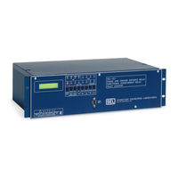
Schweitzer Engineering Laboratories SEL-321-1 Instruction Manual (396 pages)
PHASE AND GROUND DISTANCE RELAY; DIRECTIONAL OVERCURRENT RELAY; FAULT LOCATOR
Brand:
Schweitzer Engineering Laboratories
| Category:
Relays
| Size: 6.14 MB
Table of Contents
Table of Contents
11
Section 1: Introduction
7
Getting Started
13
Overview
13
Event Reporting
13
Figure 1.1: SEL-321 Front Panel (One I/O Board Version)
14
Figure 1.2: SEL-321 Rear Panel (One I/O Board Version, Showing Conventional Terminal Blocks - Other Options Are Available)
14
Figure 1.4: Three-Phase and Phase-Phase Distance Characteristics
15
Figure 1.5: Ground Distance Characteristics
16
Figure 1.6: Instantaneous, Definite-Time, and Time-Overcurrent Characteristics
16
Figure 1.7: SEL OGIC ® Control Equations Programmable Control Logic
17
Figure 1.8: SEL-5601 Analytic Assistant
17
Applications Highlights
18
Other Features
19
Electronic-Level Input Option
19
Maximum Continuous Rating
20
Relay Test System (RTS)
20
Section 2: Specifications
21
Section 2: Specifications
25
Overview
25
Setting Structure
25
Line and Relay Terminal Information
25
Table 2.1: Relay Setting Structure
25
Enabling Distance Zones
26
Element Label Comment
26
Setting the Direction of Zones and Overcurrent Elements
26
Phase Mho Distance Characteristics
26
Table 2.2: Zone and Level Elements Affected by DIR1 - DIR4
26
Phase Voltage Elements
32
Positive-Sequence Overvoltage Elements
32
Zero-Sequence Overvoltage Element
32
Communications-Assisted Tripping Schemes
33
Permissive Overreaching Transfer Trip (POTT) Logic
33
Directional Comparison Unblocking (DCUB) Logic
34
Directional Comparison Blocking (DCB) Logic
35
Creating Other Tripping Schemes
36
Direct Transfer Trip Schemes
36
Direct Underreaching Transfer Trip Schemes
36
Permissive Underreaching Transfer Trip Schemes
36
Other Logic
37
Remote-End-Just-Opened (REJO) Logic
37
Zone 1 Extension (Z1X) Scheme Logic
37
Loss-Of-Potential (LOP) Logic
38
Switch-Onto-Fault (SOTF) Logic
38
Pole-Discordance Logic
39
Pole Open Logic
40
Stub Protection Logic
40
Close Logic
41
Table 2.3: Trip Coil Monitor Logic Input Assignment Options
41
Trip Coil Monitor (TCM) Logic
41
Trip Suspicion Logic
41
Contact Input Assignments
42
Fault Identification Selection (FIDS) Logic
42
Open Phase Alarm Logic
42
Table 2.4: Logic Input Assignment List
43
Equation Programming
46
Relay Elements
47
SEL OGIC Control Equation Operator Order of Operations
47
Table 2.6: Front-Panel Status Indicators
47
Table 2.7: Primary Elements
48
Table 2.8: Primary Element Summary
48
Table 2.9: Assigned Input Statuses
52
Table 2.10: Intermediate Elements
53
Table 2.11: Intermediate Element Summary
53
Table 2.12: Internal Elements
53
Table 2.13: Internal Element Summary
54
Table 2.14: Input/Output Contact Targets (One I/O Board Version, SEL-321 Relay Only)
56
Table 2.15: Input/Output Contact Targets (Two I/O Board Version, SEL-321 Relay Only)
56
Table 2.16: Remote Bits (SEL-321-1 Relay Only)
56
Table 2.17: Remote Bit Summary (SEL-321-1 Relay Only)
57
Table 2.20: Internal Elements (SEL-321-1 Relay Only)
58
Table 2.22: Input/Output Contact Targets (One I/O Board Version, SEL-321-1 Relay Only)
60
Trip Logic
61
Table 2.23: Input/Output Contact Targets (Two I/O Board Version, SEL-321-1 Relay Only)
61
MTU (Unconditional Trip Variable)
62
Selecting Elements to Trip
62
Selecting Single-Pole or Three-Pole Tripping Logic
62
Single-Pole Tripping Conditions
62
Tripping Output Signals
62
MTCS (Communications-Scheme Trip Variable)
63
MTO (Switch-Onto-Fault Trip Variable)
63
Unlatch Logic Selections
63
Active Groups and Group Variables
64
Global Settings
64
Metering
64
System Frequency Tracking
64
Fault Locator
64
Front-Panel Targets
65
General Target LED Description
65
Table 2.27: INST and TIME LED Qualifying Elements
66
Communications Ports Specifications
68
Internal Time Clock Time-Code Synchronization Specifications
69
Self-Tests
69
Table 2.29: Self-Test Summary
70
Technical Specifications (1 a Nominal Relay)
71
General Element Ranges and Accuracy
71
Technical Specifications (5 a Nominal Relay)
73
General Element Ranges and Accuracy
73
General Specifications
75
Figure 2.4: Logic Symbol Legend
78
Figure 2.5: Zone 1 Mho Phase Distance Element Logic
79
Figure 2.7: Zone 3 Mho Phase Distance Element Logic
80
Figure 2.9: Supervisory Phase-To-Phase Overcurrent Elements
81
Figure 2.11: Zone 2 Mho Ground Distance Element Logic
82
Figure 2.14: Zone 1 Quadrilateral Ground Distance Element Logic
83
Figure 2.18: Supervisory Phase Overcurrent Elements
84
Figure 2.19: Out-Of-Step Distance Element Logic
85
Figure 2.20: Out-Of-Step Block and Trip Logic
86
Figure 2.21: Load-Encroachment Logic
87
Figure 2.22: Negative-Sequence Directional Element Logic
88
Figure 2.23: Phase Time-Overcurrent Element Logic (SEL-321 Relay Base Version)
89
Figure 2.25: Negative-Sequence Time-Overcurrent Element Logic
90
Figure 2.26: Residual Time-Overcurrent Element Logic
91
Figure 2.27: Negative-Sequence Overcurrent Element Logic for Levels 1 - 4
92
Figure 2.28: Residual Overcurrent Element Logic for Levels 1 - 4
93
Figure 2.29: Voltage Element Logic
94
Figure 2.30: Positive-Sequence Overvoltage Element Logic
95
Figure 2.32: Directional Comparison Unblocking Scheme Logic
96
Figure 2.35: Zone 1 Extension Logic
97
Figure 2.38: Loss-Of-Potential Logic
98
Figure 2.39: Pole-Discordance and Trip During Pole Open Logic
99
Figure 2.40: Pole Open Logic
100
Figure 2.43: Close Logic
101
Figure 2.46: Trip Decision Logic for Phase a
102
Distance Element Operating Time Curves at Nominal Frequency
103
Figure 2.48: Trip Unlatch Logic for Phase a
103
Time-Overcurrent Curve Equations
104
Figure 2.49: Ground and Phase Distance Speed Curves
104
Equations for US Curves
105
Equations for IEC Curves
106
Figure 2.50: Time Curve U1
107
Figure 2.54: Time Curve C1
108
Section 3: Communications
109
Communications Protocol
111
Software Protocol
111
Additional Software Protocol (SEL-321-1 Relay Only)
112
Hardware Protocol
113
Alarm Conditions
113
Main Board Jumpers
113
Automatic Messages
114
Introduction
111
Section 3: Communications
111
Command Characteristics
114
Changing Access Levels
116
Command Format
116
Description of Commands
116
2Access
116
Access
117
Breaker
117
Close
117
Comm
118
CONTROL N (SEL-321-1 Relay Only)
119
COPY M N
120
Date
120
Event
121
Group
121
History
122
Irig
123
Loop
124
Meter
125
Open
125
Password
126
PULSE N T (SEL-321-1 Relay Only)
127
Quit
127
RDMEM M (SEL-321-1 Relay Only)
127
SET Commands
127
SET N
129
Showset
132
Set G
133
Showset G
134
Set L
134
Showset L
137
Set P
138
Showset P
139
Status
140
Target
142
Time
143
Trigger
143
Front-Panel Operation
144
LCD Functions and Front-Panel Commands
144
Front-Panel Reset
145
Target Reset
145
Default Display
145
Target Command
145
Fault Command
146
Meter Display
147
Group Selector
147
Status Display
147
Diagnostic Messages
149
Password Access
149
Setting Changes Via Front Panel
149
SEL-321-1 Target Information
155
Sel-321 Relay Command Summary
157
SEL-321-1 Relay Command Summary
159
Section 4: Event Reporting
161
Event Report Generation
163
Section 4: Event Reporting
163
Summary Event Report
164
Default Event Report
165
Computer Event Report
166
Interpretation of Quarter-Cycle Voltage and Current Data
166
Long Event Report
166
MIRRORED BITS ™ Display Event Report
166
Unfiltered Event Report
166
Relay Element Columns Data
167
Contact Inputs and Outputs Columns
169
Example Event Reports
170
Example Event Report 1
170
Example Event Report 2
172
Example Event Report 2 (Continued)
173
Firmware Identification
174
Section 5: Applications
175
Purpose
177
Section 5: Applications
177
Relay Settings
178
Relay Terminal Settings
178
Identifier
178
Fault Locator Enable and Line Length
179
Positive- and Zero-Sequence Line Impedances
179
Enable Desired Distance Zones and Directional Sense
179
Phase and Ground Distance Element Setting Criteria
180
Zone 1 Setting
180
Zone 2 Setting
180
Zone 3 Setting
181
Phase Distance Overcurrent Supervision Setting Criteria
182
Zone 1 Setting
182
Zone 2 Setting
182
Zone 3 Setting
182
Ground Distance Overcurrent Supervision Setting Criteria
183
Zone 1 Setting
183
Zone 2 Setting
183
Zone 3 Setting
183
Distance Element Setting Calculations
184
Zero-Sequence Compensation Factor and Non-Homogeneous Angle Settings
185
Non-Homogeneous Angle Setting
185
Zero-Sequence Compensation Factor Setting
185
Out-Of-Step Setting
186
Load-Encroachment Logic Setting
186
Negative-Sequence Directional Element Settings
187
Phase Time-Overcurrent Element Setting
189
Residual Overcurrent Settings
189
Instantaneous/Definite-Time Residual Overcurrent Settings
189
Residual Time-Overcurrent Settings
189
Negative-Sequence Overcurrent Settings
190
Negative-Sequence Time-Overcurrent Settings
190
Voltage Elements
191
Time-Step Backup Time Delay Settings
191
Permissive Overreaching Scheme Logic
192
Directional Comparison Unblocking Scheme Logic
194
Zone 1 Extension Logic Setting
194
Remote-End-Just-Opened (REJO) Enable Setting (EREJO)
194
Switch-Onto-Fault Logic Setting
194
Loss-Of-Potential (LOP) Enable Setting (ELOP)
195
Miscellaneous Scheme Logic
198
Miscellaneous Timers
199
SEL OGIC Control Equations
200
Logic Variable Equations
200
Tripping Logic Equations
200
Event Report Trigger Condition Logic
201
Output Contact Logic
201
Global Input Settings
202
System Data
178
Settings Sheet for SEL-321 Relay Setting Example
202
Event Report Trigger Condition Logic
210
Output Contact Logic
210
Serial Port Settings
212
Serial Port Settings (See Appendix G for LMD and Appendix H for M IRRORED
212
Bits ™)
212
Section 6: Installation
233
Initial Checkout
235
Section 6: Installation
235
Mounting and Connections
236
Mounting
236
Rear-Panel Plug-In Connectors Option (Figure 6.10 through Figure 6.12)
236
Frame Ground Connection
237
Power Connections
237
Secondary Circuit Connections
237
Control Circuit Connections
237
Alarm Contact Connection
238
Control Inputs
238
Control Outputs
238
IRIG-B Input Connection
239
Communication Circuit Connections
239
Communication Cables
240
EIA-232 Cables
241
Communications
242
Modems
242
Telephone Line Communications
243
Data Flow Control
243
Baud Rate
243
Passwords
243
Jumper Settings
244
Main Board Jumpers
244
Input/Output Connections
244
Open the SEL-321 Relay to Access Internal Jumpers
244
Set Jumpers
245
Reassemble the SEL-321 Relay
245
Installation
245
SEL Direction and Polarity Check Form
263
Section 7: Maintenance and Testing
267
Initial Checkout
271
Equipment Required
271
Checkout Procedure
271
Output Contact Explanation
276
Target LED Explanation
277
Front Panel LCD Explanation
277
Section 7: Maintenance and Testing
271
Testing Philosophy
277
Acceptance Testing
278
Commissioning Testing
278
Maintenance Testing
279
Testing Methods and Tools
280
Test Aids Provided by the Relay
280
Test Methods
280
Testing Via Front Panel LCD/LED Indication
281
Testing Via Output Contact Assertion
281
Using a Breaker Simulator
282
Low-Level Test Interface
282
Test Setup
283
Test Source Connections
283
Three Voltage Source and Three Current Source Connections
283
Three Voltage Source and Two Current Source Connections
284
Three Voltage Source and One Current Source Connections
286
Serial Communication Equipment Connections
287
Test Procedures
287
Overcurrent Elements
287
Calculating Overcurrent Element Test Quantities
288
Overcurrent Element Test Examples
289
Single-Phase Overcurrent Element: 50H
289
Phase-To-Phase Overcurrent Element: 50PP2
290
Negative-Sequence Directional Element
291
Negative-Sequence Directional Element Based Upon Negative-Sequence Impedance
291
Magnitude of 3I
293
Loss-Of-Potential Supervision
294
Negative-Sequence Directional Element Test Using Single Voltage and Current Sources
294
Single-Pole Open Supervision
294
Negative-Sequence Directional Element Test Using Three Voltage Sources and One Current Source
297
Load-Encroachment Logic
302
Loss-Of-Potential Logic
302
Negative-Sequence Directional Element
302
Phase Distance Element Supervisory Conditions
302
Phase-To-Phase Nondirectional Overcurrent Element, 50Ppn
302
Single-Pole Open Logic
302
Out-Of-Step Blocking Logic
303
Phase Distance Element Test Using Three Voltage Sources and One Current Source
303
Ground Mho Distance Elements
308
Ground Distance Element Supervisory Conditions
309
Loss-Of-Potential Logic
309
Phase and Ground Nondirectional Overcurrent Elements, 50Ln and 50Gn
309
Single-Pole Open Logic
309
Three-Pole Open Logic
309
Ground Distance Element Disable Inputs
310
Ground Mho Distance Element Test Using Three Voltage Sources and One Current Source
310
Ground Quadrilateral Distance Element Reactive Reach Test Using Three Voltage Sources and One Current Source
315
Ground Quadrilateral Distance Element Resistive Reach Test Using Three Voltage Sources and One Current Source
319
Inspection Procedure
325
Troubleshooting Procedure
325
All Front Panel Leds Dark
325
Cannot See Characters on Relay LCD Screen
326
No Prompting Message Issued to Terminal Upon Power-Up
326
Relay Does Not Respond to Commands from Device Connected to Serial Port
326
Tripping Output Relay Remains Closed Following Fault
326
Table of Contents
331
Appendix A: Firmware Versions in this Manual
333
Appendix B: Sel-321 Main Board Jumper, Connector, and Socket Locations
359
Appendix C: Application Guidelines
361
Appendix D: Onebus: Program to Compute Test Set Settings for Testing Distance Relays
363
Appendix E: Sel-5601 Analytic Assistant
365
Appendix F: Special Application Settings
367
Appendix G: Additional Sel-321-1 Relay Communications Protocol
369
Appendix H: Mirrored Bits ™ Communications
371
Overview
371
Settings
371
Operation
373
Message Decoding and Integrity Checks
373
Message Transmission
373
Channel Monitoring
375
Loopback Testing
375
Synchronization
375
Advertisement
Advertisement
Related Products
Schweitzer Engineering Laboratories SEL-321-5
Schweitzer Engineering Laboratories SEL-321-2
Schweitzer Engineering Laboratories SEL-321-3
Schweitzer Engineering Laboratories SEL-321
Schweitzer Engineering Laboratories SEL-351S
Schweitzer Engineering Laboratories SEL-387-6
Schweitzer Engineering Laboratories SEL-351-3
Schweitzer Engineering Laboratories SEL-351-5
Schweitzer Engineering Laboratories SEL-351-7
Schweitzer Engineering Laboratories SEL-387E
Schweitzer Engineering Laboratories Categories
Relays
Computer Hardware
Transceiver
Protection Device
Measuring Instruments
More Schweitzer Engineering Laboratories Manuals
Login
Sign In
OR
Sign in with Facebook
Sign in with Google
Upload manual
Upload from disk
Upload from URL