Sign In
Upload
Manuals
Brands
Schweitzer Engineering Laboratories Manuals
Relays
SEL-311C
Schweitzer Engineering Laboratories SEL-311C Manuals
Manuals and User Guides for Schweitzer Engineering Laboratories SEL-311C. We have
2
Schweitzer Engineering Laboratories SEL-311C manuals available for free PDF download: Instruction Manual
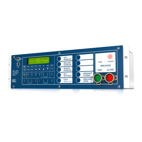
Schweitzer Engineering Laboratories SEL-311C Instruction Manual (748 pages)
Protection and Automation System
Brand:
Schweitzer Engineering Laboratories
| Category:
Relays
| Size: 5.79 MB
Table of Contents
Table of Contents
3
List of Tables
13
List of Figures
17
Preface
23
Manual Overview
23
Page Numbering
26
Conventions
27
Typographic Conventions
27
Examples
27
Safety Information
28
Overview
29
SEL-311C Models
30
Table 1.1 SEL-311C Models
30
Applications
31
Figure 1.1 SEL-311C Transmission Line Protection with Pilot Protection
31
AC/DC Connections
32
Dual Terminal Labels
32
Figure 1.2 SEL-311C Inputs, Outputs, and Communications Ports (Models 0311C00X and 0311C01X)
33
Output Contacts
34
Figure 1.3 SEL-311C Extra I/O Board (Model 0311C01X)
35
Communications Connections
36
Figure 1.4 SEL-311C Communications Connections Examples
36
Specifications
38
Section 2: Installation
43
Relay Mounting
43
Figure 2.1 SEL-311C Dimensions and Panel-Mount Cutout
43
Front- and Rear-Panel Diagrams
44
Figure 2.2 SEL-311C Front- and Rear-Panel Drawings-Models 0311C00H2 (Rack) and 0311C0032 (Panel)
44
Figure 2.3 SEL-311C Front- and Rear-Panel Drawings-Models 0311C00V1 (Rack) and 0311C0041 (Panel)
45
Figure 2.4 SEL-311C Front-Panel Drawings-Models 0311C01H2 (Rack) and 0311C0132 (Panel)
46
Figure 2.5 SEL-311C Front-Panel Drawings-Models 0311C01H1 (Rack) and 0311C0131 (Panel)
47
Figure 2.6 SEL-311C Front-Panel Drawings-Models 0311C01V1 and 0311C01V2
48
Figure 2.7 SEL-311C Front-Panel Drawings-Models 0311C0141 and 0311C0142
49
Figure 2.8 SEL-311C 3U Rear-Panel Terminal Block Drawings (with and Without Additional I/O Board)
50
Figure 2.9 SEL-311C 3U Rear-Panel Terminal Block Drawing (Fast Hybrid High-Current Interrupting Output Contacts)
51
Figure 2.10 SEL-311C 2U Rear-Panel Connectorized ® Drawing
52
Figure 2.11 SEL-311C 3U Rear-Panel Connectorized Drawings (with and Without Additional I/O Board)
53
Making Rear-Panel Connections
54
Wire-Alike Screw Terminal Connections
54
Power Supply
54
Output Contacts
54
Optoisolated Inputs
56
Current Transformer Inputs
56
Potential Transformer Inputs
56
Wye-Connected Voltages
56
Serial Ports
56
Figure 2.12 Possible Connections for Fast High-Current Interrupting Output Contacts (Circuit Load Not Shown, Third Terminal Connection Is Optional)
56
IRIG-B Time-Code Input
57
Table 2.1 Communications Cables to Connect the SEL-311C to Other Devices
57
SEL-311C AC/DC Connection Diagrams for Various Applications
58
Figure 2.13 SEL-311C Provides Distance and Overcurrent Protection, Reclosing, and Synchronism Check for a Transmission Line
58
Figure 2.14 SEL-311C Provides Distance and Overcurrent Protection and Reclosing for a Transmission Line (Current-Polarization Source Connected to Channel IP)
59
Figure 2.15 SEL-311C Line Protection through a Delta-Wye Transformer Using Compensator Distance Elements
60
Circuit Board Connections
61
Accessing the Relay Circuit Boards
61
Figure 2.16 Jumper, Connector, and Major Component Locations on the SEL-311C Main Board
62
Figure 2.17 Jumper, Connector, and Major Component Locations on the SEL-311C Extra I/O Board
63
Figure 2.18 Interface Board 5 Component Layout
64
Output Contact Jumpers
65
Extra Alarm" Output Contact Control Jumper
65
Table 2.2 Output Contact Jumpers and Corresponding Output Contacts
65
Password and Breaker Jumpers
66
Table 2.3 Move Jumper JMP 23 to Select Extra Alarm
66
Table 2.4 Password and Breaker Jumper Operation
66
Serial Port Voltage Jumpers
67
Clock Battery
67
Table 2.5 EIA-232 Serial Port Voltage Jumper Positions for Standard Relay Shipments
67
Frequency Elements
69
Distance Elements
69
Mho Phase Distance Elements
69
Table 3.1 Phase Distance Calculations
70
Figure 3.1 Positive-Sequence Polarized Mho Element with Reach Equal to Line Impedance
71
Figure 3.2 Compensator-Distance Phase-To-Phase Element Operation
72
Figure 3.3 Compensator-Distance Three-Phase Element Operation
73
Table 3.2 Distance Elements Settings
74
Figure 3.4 Zone 1 AB Phase Distance Logic
75
Figure 3.5 Zone 2 AB Phase Distance Logic
76
Figure 3.6 Zones 3 and 4 AB Phase Distance Logic
77
Ground Distance Elements
78
Table 3.3 Ground Distance Elements Settings
78
Figure 3.7 Zone 1 Mho Ground Distance Logic
79
Figure 3.8 Zone 2 Mho Ground Distance Logic
80
Figure 3.9 Zones 3 and 4 Mho Ground Distance Logic
80
Figure 3.10 Zone 1 Quadrilateral Ground Distance Logic
81
Figure 3.11 Zone 2 Quadrilateral Ground Distance Logic
82
Figure 3.12 Zones 3 and 4 Quadrilateral Ground Distance Logic
83
Distance Element Operating Time Curves at Nominal Frequency
84
Figure 3.13 Ground and Phase Distance Speed Curves-Standard Output
85
Figure 3.14 Ground and Phase Distance Speed Curves-Fast Hybrid Output
86
Additional Distance Element Supervision
87
Figure 3.15 Zone 1 Extension Logic
87
Table 3.4 Zone 1 Settings
87
Zone 1 Extension
87
Table 3.5 Zone Timing Settings
88
Zone Time Delay Elements
88
Figure 3.16 Zone Timing Elements
89
Out-Of-Step Characteristics
90
Use SEL-321 Relay Application Guides for the SEL-311C
90
Table 3.6 Out-Of-Step Settings
90
Table 3.7 OOS Relay Word Bits
91
Figure 3.17 Out-Of-Step Zone Detection Logic
92
Figure 3.18 Out-Of-Step Logic
93
Instantaneous/Definite-Time Overcurrent Elements
94
Phase Instantaneous/Definite-Time Overcurrent Elements
94
Figure 3.19 Levels 1 through 3 Phase Instantaneous/Definite-Time Overcurrent Elements
95
Residual Ground Instantaneous/Definite-Time Overcurrent Elements
96
Figure 3.20 SEL-311C Nondirectional Instantaneous Overcurrent Element Pickup Time Curve
96
Figure 3.21 SEL-311C Nondirectional Instantaneous Overcurrent Element Reset Time Curve
96
Figure 3.22 Levels 1 through 4 Residual Ground Instantaneous
97
Negative-Sequence Instantaneous/Definite-Time Overcurrent Elements
98
Figure 3.23 Levels 1 through 4 Negative-Sequence Instantaneous
100
Time-Overcurrent Elements
101
Phase Time-Overcurrent Elements
101
Table 3.8 Available Phase Time-Overcurrent Elements
101
Table 3.9 Phase Time-Overcurrent Element (Maximum Phase) Settings
101
Table 3.10 Phase Time-Overcurrent Element (Maximum Phase) Logic Outputs
102
Figure 3.24 Phase Time-Overcurrent Element 51PT
102
Residual Ground Time-Overcurrent Element
104
Table 3.11 Residual Ground Time-Overcurrent Element Settings
105
Figure 3.25 Residual Ground Time-Overcurrent Element 51GT
105
Negative-Sequence Time-Overcurrent Element
106
Table 3.12 Negative-Sequence Time-Overcurrent Element Settings
106
Figure 3.26 Negative-Sequence Time-Overcurrent Element 51QT
106
Voltage Elements
108
Voltage Values
108
Voltage Element Settings
108
Table 3.13 Voltage Values Used by Voltage Elements
108
Table 3.14 Voltage Elements Settings and Settings Ranges
108
Figure 3.27 Single-Phase and Three-Phase Voltage Elements
109
Voltage Element Operation
110
Figure 3.28 Phase-To-Phase and Sequence Voltage Elements
110
Figure 3.29 Channel V S Voltage Elements
110
Synchronism Check Elements
112
Fixed Angle Synchronism Check
112
Dynamic Synchronism Check
112
Synchronism Check Elements Settings
113
Table 3.15 Synchronism Check Elements Settings and Settings Ranges
113
Figure 3.30 Synchronism Check Voltage Window and Slip Frequency Elements
114
Figure 3.31 Synchronism Check Elements
114
Synchronism Check Elements Voltage Inputs
116
Synchronism Check Elements Operation
116
Figure 3.32 Angle Difference between V
119
Synchronism Check Applications for Automatic Reclosing and Manual Closing
122
Frequency Elements
123
Frequency Element Settings
123
Figure 3.33 Undervoltage Block for Frequency Elements
123
Figure 3.34 Levels 1 through 6 Frequency Elements
124
Table 3.16 Frequency Elements Settings and Settings Ranges
125
Frequency Element Operation
126
Frequency Element Uses
127
Section 4: Loss-Of-Potential, CCVT Transient Detection, Load-Encroachment, and Directional Element Logic
129
Loss-Of-Potential Logic
129
Figure 4.1 Loss-Of-Potential Logic
129
Setting ELOP
130
Setting ELOP = y or Y1
130
Setting ELOP = N
131
CCVT Transient Detection Logic
132
Figure 4.2 CCVT Transient Blocking Logic
132
Load-Encroachment Logic
133
Figure 4.3 Load-Encroachment Logic with Example Settings
133
Load-Encroachment Setting Example
134
Settings Ranges
134
Table 4.1 Load-Encroachment Logic Settings Ranges
134
Figure 4.4 Migration of Apparent Positive-Sequence Impedance for a Fault Condition
136
Use SEL-321 Relay Application Guide for the SEL-311C
136
Directional Control for Ground Distance and Residual Ground Overcurrent Elements
137
Figure 4.5 General Logic Flow of Directional Control for Ground Distance and Residual Ground Overcurrent Elements
137
Best Choice Ground Directional Logic
138
Directional Element Enables
138
Directional Element Routing
138
Directional Elements
138
Figure 4.6 Internal Enables (32QE and 32QGE) Logic
139
Figure 4.7 Internal Enables (32VE and 32IE) Logic for Zero-Sequence
140
Figure 4.8 Best Choice Ground Directional Logic
141
Figure 4.9 Negative-Sequence Voltage-Polarized Directional Element for Ground Distance and Residual Ground Overcurrent Elements
142
Figure 4.10 Zero-Sequence Voltage-Polarized Directional Element for Ground Distance and Residual Ground Overcurrent Elements
143
Figure 4.11 Channel IP Current-Polarized Directional Element for Ground Distance and Residual Ground Overcurrent Elements
144
Figure 4.12 Ground Distance and Residual Ground Directional Logic
144
Directional Control for Phase Distance and Negative-Sequence Elements
145
Internal Enables
145
Directional Elements
145
Figure 4.13 General Logic Flow of Directional Control for Negative-Sequence Phase Overcurrent and Phase Distance Elements
145
Directional Element Routing
146
Figure 4.14 Negative-Sequence Voltage-Polarized Directional Element for Phase Distance and Negative-Sequence Elements
147
Figure 4.15 Positive-Sequence Voltage Polarized Directional Element for Phase Distance Elements
148
Directional Control Settings
149
Settings Made Automatically
149
Settings
149
Table 4.2 Elements Controlled by Zone/Level Direction Settings (Corresponding Overcurrent and Directional Element Figure Numbers in Parentheses)
149
Table 4.3 First Entry in ORDER Setting if Ground Quadrilateral Distance Elements Are Used
151
Overcurrent Directional Control Provided by Torque Control Settings
156
Table 4.4 Torque Control Settings and Elements
156
Section 5: Trip and Target Logic Trip Logic
158
Figure 5.1 Trip Logic
158
Figure 5.2 Minimum Trip Duration Timer Operation (See Bottom of Figure 5.1)
159
Set Trip
159
Factory Settings Example (Using Setting
160
Unlatch Trip
160
Additional Settings Examples
161
Program an Output Contact for Tripping
162
Switch-Onto-Fault Trip Logic
163
Figure 5.3 Three-Pole Open Logic (Top) and Switch-Onto-Fault Logic (Bottom)
163
Circuit Breaker Operated Switch-Onto-Fault Logic
164
Three-Pole Open Logic
164
Close Bus Operated Switch-Onto-Fault Logic
165
Switch-Onto-Fault Logic Output (SOTFE)
165
Switch-Onto-Fault Trip Logic Trip Setting (TRSOTF)
165
Communications-Assisted Trip Logic-General Overview
166
Enable Setting ECOMM
166
Figure 5.4 Communications-Assisted Tripping Scheme
166
Trip Setting TRCOMM
167
Trip Settings TRSOTF and TR
167
Trip Setting DTT
167
Use Existing SEL-321 Relay Application Guides for the SEL-311C Relay
168
Permissive Overreaching Transfer Trip Logic
169
External Inputs
169
Timer Settings
170
Logic Outputs
170
Figure 5.5 Permissive Input Logic Routing to POTT Logic
170
Weak-Infeed Logic and Settings
171
SEL-311C Weak-Infeed Logic
171
Figure 5.6 POTT Logic
172
Installation Variations
173
Figure 5.7 Permissive Input Logic Routing to Trip Logic
173
Variations for Permissive Underreaching Transfer Trip (PUTT) Scheme
173
Figure 5.8 SEL-311C Connections to Communications Equipment for a Two-Terminal Line POTT Scheme
174
Figure 5.9 SEL-311C Connections to Communications Equipment for a Three-Terminal Line POTT Scheme
174
Directional Comparison Unblocking Logic
175
Use Existing SEL-321 DCUB Application Guide for the SEL-311C
175
External Inputs
175
Timer Settings
176
Logic Outputs
176
Figure 5.10 DCUB Logic
178
Installation Variations
179
Figure 5.11 Unblocking Block Logic Routing to Trip Logic
179
Figure 5.12 SEL-311C Connections to Communications Equipment for a Two-Terminal Line DCUB Scheme (Setting ECOMM = DCUB1)
179
Figure 5.13 SEL-311C Connections to Communications Equipment for a Three-Terminal Line DCUB Scheme (Setting ECOMM = DCUB2)
180
Directional Comparison Blocking Logic
181
External Inputs
181
Timer Settings
181
Logic Outputs
182
Installation Variations
184
Figure 5.14 DCB Logic
184
Figure 5.15 SEL-311C Connections to Communications Equipment for a Two-Terminal Line DCB Scheme
185
Figure 5.16 SEL-311C Connections to Communications Equipment for a Three-Terminal Line DCB Scheme
186
Front-Panel Target Leds
187
Additional Target LED Information
187
Table 5.1 SEL-311C Front-Panel Target LED Definitions
187
TARGET RESET/LAMP TEST} Front-Panel Pushbutton
189
Figure 5.17 Seal-In of Breaker Failure Occurrence for Message Display
190
Section 6: Close and Reclose Logic
191
Overview
191
Close Logic
191
Reclose Supervision Logic
191
Reclose Logic
191
Close Logic
192
Set Close
192
Unlatch Close
193
Factory Settings Example
193
Defeat the Close Logic
194
Circuit Breaker Status
194
Program an Output Contact for Closing
194
Reclose Supervision Logic
195
Figure 6.2 Reclose Supervision Logic (Following Open Interval Time-Out)
195
Figure 6.3 Reclose Supervision Limit Timer Operation (Refer to Bottom of Figure 6.2)
196
Settings and General Operation
196
Additional Settings Example
198
Settings Example 1
198
Figure 6.4 SEL-311C Relays Installed at both Ends of a Transmission Line in a High-Speed Reclose Scheme
199
Additional Settings Example 2
200
Reclosing Relay
201
Reclosing Relay States and General Operation
201
Figure 6.5 Reclosing Relay States and General Operation
201
Table 6.1 Relay Word Bit and Front-Panel Correspondence to Reclosing Relay States
202
Reclosing Relay States after a Settings or Setting Group Change
203
Defeat the Reclosing Relay
203
Reclosing Relay Timer Settings
204
Table 6.2 Reclosing Relay Timer Settings and Setting Ranges
204
Figure 6.1 Close Logic
204
Figure 6.6 Reclosing Sequence from Reset to Lockout with Example Settings
205
Reclosing Relay Shot Counter
206
Table 6.3 Relay Word Bits Used to Monitor Open Interval and Reset Timing
206
Reclosing Relay SEL OGIC Control Equation Settings Overview
207
Table 6.4 Shot Counter Correspondence to Relay Word Bits and Open Interval Times
207
Reclose Initiate and Reclose Initiate Supervision Settings (79RI and 79RIS, Respectively)
207
Drive-To-Lockout and Drive-To-Last Shot Settings (79DTL and 79DLS, Respectively)
209
Skip Shot and Stall Open Interval Timing Settings (79SKP and 79STL, Respectively)
211
Table 6.6 Open Interval Time Settings Example
212
Block Reset Timing Setting (79BRS)
213
Figure 6.7 Reclose Blocking for Islanded Generator
213
Sequence Coordination Setting (79SEQ)
214
Section 7: Inputs, Outputs, Timers, and Other Control Logic Overview
216
Optoisolated Inputs
217
Figure 7.1 Example Operation of Optoisolated Inputs IN101 through IN106 (Models 0311C00X and 0311C01X)
217
Figure 7.2 Example Operation of Optoisolated Inputs IN1201 through IN208-Extra I/O Board (Model 0311C01X)
218
Input Debounce Timers
218
Input Functions
218
Figure 7.3 Circuit Breaker Auxiliary Contact and Reclose Enable Switch Connected to Optoisolated Inputs IN101 and IN102
219
Settings Example 1
219
Local Control Switches
221
Local Control Switch Types
221
Table 7.1 Correspondence between Local Control Switch Positions and Label Settings
221
Figure 7.4 Local Control Switches Drive Local Bits LB1 through LB16
221
Table 7.2 Correspondence between Local Control Switch Types and Required Label Settings
222
Figure 7.5 Local Control Switch Configured as an ON/OFF Switch
222
Figure 7.6 Local Control Switch Configured as an OFF/MOMENTARY Switch
222
Figure 7.7 Local Control Switch Configured as an ON/OFF/MOMENTARY Switch
222
Settings Examples
223
Table 7.3 Local Bits LB3 and LB4 Used for Manual Trip and Close Functions
223
Figure 7.8 Configured Manual Trip Switch Drives Local Bit LB3
223
Figure 7.9 Configured Manual Close Switch Drives Local Bit LB4
223
Additional Local Control Switch Application Ideas
224
Local Control Switch States Retained
224
Remote Control Switches
225
Remote Bit Application Ideas
225
Remote Bit States Not Retained When Power Is Lost
225
Remote Bit States Retained When Settings Changed or Active Setting Group Changed
225
Figure 7.10 Remote Control Switches Drive Remote Bits RB1 through RB16
225
Latch Control Switches
227
Figure 7.11 Traditional Latching Relay
227
Figure 7.12 Latch Control Switches Drive Latch Bits LT1 through LT16
227
Figure 7.13 SCADA Contact Pulses Input IN104 to Enable/Disable Reclosing Relay
228
Figure 7.14 Latch Control Switch Controlled by a Single Input to Enable/Disable Reclosing
228
Latch Control Switch Application Ideas
228
Reclosing Relay Enable/Disable Setting Example
228
Figure 7.15 Latch Control Switch Operation Time Line
230
Latch Control Switch States Retained
230
Figure 7.16 Time Line for Reset of Latch Bit LT2 after Active Setting Group Change
231
Make Latch Control Switch Settings with Care
231
Reset Latch Bits for Active Setting Group Change
231
Figure 7.17 Latch Control Switch (with Time Delay Feedback) Controlled by a Single Input to Enable/Disable Reclosing
232
Figure 7.18 Latch Control Switch (with Time Delay Feedback) Operation Time Line
232
Multiple Setting Groups
233
Active Setting Group Indication
233
Selecting the Active Setting Group
233
OGIC Control Equation Settings SS1-SS6
233
Table 7.4 Definitions for Active Setting Group Indication Relay Word Bits SG1-SG6
233
Table 7.5 Definitions for Active Setting Group Switching
233
Operation of Settings SS1-SS6
234
Operation of Serial Port GROUP Command and Front-Panel {GROUP} Pushbutton
234
Relay Disabled Momentarily During Active Setting Group Change
234
Active Setting Group Switching Example
234
Table 7.6 SEL OGIC Control Equation Settings for Switching Active Setting Group between Setting Groups 1 and
235
Figure 7.19 SCADA Contact Pulses Input IN105
235
Figure 7.20 SEL OGIC Control Equation Variable Timer SV8T Used in Setting Group Switching
235
Active Setting Group Switching Example
237
Table 7.7 Active Setting Group Switching Input Logic
237
Figure 7.21 Active Setting Group Switching (with Single Input) Time Line
237
Figure 7.22 Rotating Selector Switch Connected to Inputs IN101, IN102, and IN103 for Active Setting Group Switching
238
Active Setting Group Retained
240
Figure 7.23 Active Setting Group Switching (with Rotating Selector Switch) Time Line
240
Make Active Setting Group Switching Settings with Care
241
SEL OGIC Control Equation Variables/Timers
242
Settings Example 1
243
Additional Settings Example
243
Figure 7.26 Dedicated Breaker Failure Scheme Created
244
Additional Settings Example 2
244
Output Contacts
246
Factory Settings Example
246
Operation of Output Contacts for Different Output Contact Types
246
Figure 7.27 Logic Flow for Example Output Contact Operation (Models 0311C00X and 0311C01X)
248
Figure 7.28 Logic Flow for Example Output Contact Operation-Extra I/O Board (Model 0311C01X)
249
Rotating Default Display (Only on Models with LCD)
250
Traditional Indicating Panel Lights
250
Traditional Indicating Panel Lights Replaced with Rotating Default Display
250
Figure 7.29 Traditional Panel Light Installations
250
General Operation of Rotating Default Display Settings
251
Settings Examples
251
Figure 7.30 Rotating Default Display Replaces Traditional Panel Light Installations
251
Additional Settings Examples
253
Active Setting Group Switching Considerations
254
Additional Rotating Default Display Example
255
Displaying Time-Overcurrent Elements on the Rotating Default Display
255
Displaying Time-Overcurrent Elements Example
256
Table 7.9 Settings for Displaying Time-Overcurrent Elements
256
Displaying Metering Quantities on the Rotating Default Display
257
Table 7.10 Relay Setting Variables
257
Table 7.11 Mnemonic Settings for Metering on the Rotating Default Display
258
Displaying Metering Values Example
260
Table 7.12 Settings for Displaying Metering Values Example
260
Displaying Breaker Monitor Outputs Example
261
Table 7.13 Mnemonic Settings for Self-Check Status on the Rotating Default Display
261
Table 7.14 Settings for Displaying Breaker Monitor Outputs Example
261
Overview
263
Breaker Monitor
264
Table 8.1 Breaker Maintenance Information for an Example Circuit Breaker
264
Figure 8.1 Plotted Breaker Maintenance Points for an Example Circuit Breaker
265
Breaker Monitor Setting Example
266
Table 8.2 Breaker Monitor Settings and Settings Ranges
266
Figure 8.2 SEL-311C Breaker Maintenance Curve for an Example Circuit Breaker
267
Breaker Monitor Operation Example
268
Figure 8.3 Operation of SEL OGIC Control Equation Breaker Monitor Initiation Setting
268
Figure 8.4 Breaker Monitor Accumulates 10 Percent Wear
270
Figure 8.5 Breaker Monitor Accumulates 25 Percent Wear
271
Figure 8.6 Breaker Monitor Accumulates 50 Percent Wear
272
Breaker Monitor Output
273
Figure 8.7 Breaker Monitor Accumulates 100 Percent Wear
273
Table 8.3 Breaker Monitor Output Relay Word Bits
274
View or Reset Breaker Monitor Information
274
Determination of Relay-Initiated Trips and Externally Initiated Trips
275
Figure 8.8 Input IN106 Connected to Trip Bus for Breaker Monitor Initiation
275
Station DC Battery Monitor
277
DC Under- and Overvoltage Elements
277
Create Desired Logic for DC Under- and Overvoltage Alarming
277
Figure 8.9 DC Under- and Overvoltage Elements
277
Additional Application
279
View Station DC Battery Voltage
279
Analyze Station DC Battery Voltage
279
Operation of Station DC Battery Monitor When AC Voltage Is Powering the Relay
281
Demand Metering
282
Comparison of Thermal and Rolling Demand Meters
282
Figure 8.11 Response of Thermal and Rolling Demand Meters to a Step Input
283
Figure 8.12 Current I S Applied to Parallel RC Circuit
284
Demand Meter Settings
286
Table 8.4 Demand Meter Settings and Settings Range
286
Figure 8.13 Demand Current Logic Outputs
286
Demand Current Logic Output Application-Raise Pickup for Unbalance Current
287
Figure 8.14 Raise Pickup of Residual Ground Time-Overcurrent Element for Unbalance Current
287
View or Reset Demand Metering Information
288
Demand Metering Updating and Storage
289
Energy Metering
290
View or Reset Energy Metering Information
290
Energy Metering Updating and Storage
290
Maximum/Minimum Metering
291
Maximum/Minimum Metering Updating and Storage
291
Synchrophasor Metering
293
Overview
295
Table 9.1 Serial Port SET Commands
295
Settings Changes Via the Front Panel
296
Settings Changes Via the Serial Port
297
Table 9.2 SET Command Editing Keystrokes
297
Time-Overcurrent Curves
299
Table 9.3 Equations Associated with U.S. Curves
299
Table 9.4 Equations Associated with I.E.C. Curves
299
Figure 9.1 U. S. Moderately Inverse Curve: U1
300
Figure 9.2 U. S. Inverse Curve: U2
301
Figure 9.3 U. S. very Inverse Curve: U3
302
Figure 9.4 U. S. Extremely Inverse Curve: U4
303
Figure 9.5 U. S. Short-Time Inverse Curve: U5
304
Figure 9.6 I. E. C. Class a Curve (Standard Inverse): C1
305
Figure 9.7 I. E. C. Class B Curve (very Inverse): C2
306
Figure 9.8 I. E. C. Class C Curve (Extremely Inverse): C3
307
Figure 9.9 I. E. C. Long-Time Inverse Curve: C4
308
Figure 9.10 I. E. C. Short-Time Inverse Curve: C5
309
Table 9.5 SEL-311C Models 0311C00X and 0311C01X Relay Word Bits
310
Table 9.6 Relay Word Bit Definitions for the SEL-311C
311
Relay Word Bits (Used in SEL OGIC Control Equations)
313
Settings Explanations
327
Identifier Labels
327
Current Transformer Ratios
327
Line Settings
327
Enable Settings
328
Other System Parameters
328
Settings Sheets
329
Settings Sheets for the SEL-311C Relay
331
Overview
363
Port Connector and Communications Cables
364
Irig-B
364
Table 10.1 Pinout Functions for EIA-232 Serial Ports 2, 3, and
364
Table 10.2 Terminal Functions for EIA-485 Serial Port 1
364
Figure 10.1 DB-9 Connector Pinout for EIA-232 Serial Ports
364
Relay Word Bit TIRIG
365
Relay Word Bit TSOK
365
SEL-311C to Computer
365
SEL-311C to Modem or Other DCE
365
SEL-311C to SEL-DTA2
366
SEL-311C to SEL-PRTU
366
Table 10.3 Serial Communications Port Pin/Terminal Function Definitions
366
SEL-311C to SEL Communications Processor or SEL-2100
366
Communications Protocols
368
Software Protocols
368
Serial Port Automatic Messages
371
SEL-DTA Protocol
371
Table 10.4 Serial Port Automatic Messages
371
Serial Port Access Levels
372
Access Level 0
372
Access Level 2
373
Command Summary
374
Table 10.5 Serial Port Command Summary
374
Command Explanations
376
Access Level 1 Commands
377
Table 10.6 Event Types
381
Table 10.7 SHO Command Options
387
Table 10.8 STA Command Row and Column Definitions
392
Table 10.9 TAR Command Options
394
Table 10.10 SEL-311C Relay Word and Its Correspondence to TAR Command
394
Access Level B Commands
396
Table 10.11 SEL-311C Control Subcommands
399
Access Level 2 Commands
399
SEL-311C Relay Command Summary
403
Section 11: Front-Panel Interface (Only on Models with LCD)
407
Overview
407
Front-Panel Pushbutton Operation
408
Overview
408
Primary Functions
408
Figure 11.1 SEL-311C Front-Panel Pushbuttons-Overview
408
Figure 11.2 SEL-311C Front-Panel Pushbuttons-Primary Functions
409
Secondary Functions
410
Figure 11.3 SEL-311C Front-Panel Pushbuttons-Primary Functions (Continued)
410
Figure 11.4 SEL-311C Front-Panel Pushbuttons-Secondary Functions
411
Functions Unique to the Front-Panel Interface
412
Reclosing Relay Shot Counter Screen
412
Local Control
414
Figure 11.5 Local Control Switch Configured as an ON/OFF Switch
414
Figure 11.6 Local Control Switch Configured as an OFF/MOMENTARY Switch
414
Figure 11.7 Local Control Switch Configured as an ON/OFF/MOMENTARY Switch
415
Rotating Default Display
418
Figure 11.8 Correspondence between Changing Display Point States and Enabled Display Point Labels
420
Exit
421
Restart Scrolling (Unlock)
421
Scroll Lock Control of Front Panel LCD
421
Single Step
421
Stop Scrolling (Lock)
421
Additional Rotating Default Display Example
422
Cancel
422
Section 12: Standard Event Reports and SER
423
Overview
423
Standard 15/30/60/180-Cycle Event Reports
424
Event Report Length (Settings LER and PRE)
424
Standard Event Report Triggering
424
Event Summary
425
Figure 12.1 Example Event Summary
426
Table 12.1 Event Types
427
Retrieving Full-Length Standard Event Reports
428
Synchrophasor-Level Accuracy in Event Reports
429
Table 12.2 Example EVE Commands
429
Compressed ASCII Event Reports
430
Filtered and Unfiltered Event Reports
430
Figure 12.2 Example Synchrophasor-Level Precise Event Report 1/16-Cycle Resolution
430
Clearing Standard Event Report Buffer
431
Standard Event Report Column Definitions
431
Table 12.3 Standard Event Report Current, Voltage, and Frequency Columns
431
Table 12.4 Output, Input, Protection, and Control Element Event Report Columns
432
Table 12.5 Communication Elements Event Report Columns
437
Example Standard 15-Cycle Event Report
441
Figure 12.3 Example Standard 15-Cycle Event Report 1/4-Cycle Resolution
446
Figure 12.4 Derivation of Event Report Current Values and RMS Current Values from Sampled Current Waveform
447
Figure 12.5 Derivation of Phasor RMS Current Values from Event Report Current Values
448
Sequential Events Recorder (SER) Report
450
SER Triggering
450
Making SER Trigger Settings
450
Make SER Settings with Care
450
Retrieving SER Reports
450
Table 12.6 Example SER Serial Port Commands and Results
451
Clearing SER Report
452
Example Sequential Events Recorder (SER) Report
453
Figure 12.6 Example Sequential Events Recorder (SER) Event Report
453
Section 13: Testing and Troubleshooting
455
Overview
455
Testing Philosophy
456
Acceptance Testing
456
Commissioning Testing
456
Maintenance Testing
457
Testing Methods and Tools
459
Test Features Provided by the Relay
459
Table 13.1 Features Useful for Relay Testing
459
Low-Level Test Interface
460
Test Methods
460
Relay Testing
463
Equipment Required
463
Table 13.2 Fault Locator Test Values
467
Table 13.3 Output Contact and Target LED Results
467
Output Contact Explanation
468
Target LED Explanation
468
Front-Panel LCD Explanation
468
Test Setup
469
Test Source Connections
469
Figure 13.2 Three Voltage Source and Three Current Source Test Connections
469
Figure 13.3 Phase-To-Phase, Phase-To-Ground, and Two-Phase-To-Ground Fault Test Connections Using Two Current Sources
470
Figure 13.4 Three-Phase Fault and METER Test Connections Using Two Current Sources
471
Figure 13.5 Phase-To-Ground Fault Test Connections Using a Single Current Source
472
Serial Communications Equipment Connections
473
Figure 13.6 Phase-To-Phase Fault Test Connections Using a Single Current Source
473
Figure 13.7 Communications Connections between the SEL-311C and a Terminal
473
Test Procedures
474
Overcurrent Elements
474
Table 13.4 Types of Overcurrent Elements
475
Negative-Sequence Directional Element
476
Phase Mho Distance Elements
487
Table 13.5 Test Quantities for Zone 2 Phase Distance Element
489
Figure 13.8 Phase Distance Element Test Voltage Signals
491
Ground Mho Distance Elements
493
Table 13.6 Test Quantities for Zone 2 Ground Mho Distance Element
496
Table 13.7 Test Quantities for Zone 2 Ground Quadrilateral Distance Element: Reactive Reach
501
Table 13.8 Test Quantities for Zone 2 Ground Quadrilateral Distance Element: Resistive Reach
506
Troubleshooting Test Results
510
Table 13.9 Test Result Problems
510
Relay Self-Tests
512
Table 13.10 Relay Self Tests
512
Relay Troubleshooting
514
Inspection Procedure
514
Table 13.11 Troubleshooting Procedure
514
Relay Calibration
515
Factory Assistance
516
Advertisement
Schweitzer Engineering Laboratories SEL-311C Instruction Manual (734 pages)
PROTECTION AND AUTOMATION SYSTEM
Brand:
Schweitzer Engineering Laboratories
| Category:
Protection Device
| Size: 7.6 MB
Table of Contents
Table of Contents
11
Introduction and Specifications
13
SEL-311C Relay Models
13
Table 1.1: SEL-311C Relay Models
13
Instruction Manual Sections Overview
14
Applications
17
AC/DC Connections
17
Figure 1.1: SEL-311C Relay Transmission Line Protection with Pilot Protection, MIRRORED
17
BITS , Reclosing, and Synch Check
17
Figure 1.2: SEL-311C Relay Inputs, Outputs, and Communications Ports (Models 0311C00X and 0311C01X)
18
Figure 1.3: SEL-311C Relay Extra I/O Board (Model 0311C01X)
19
Communications Connections
20
Figure 1.4: SEL-311C Relay Communications Connections Examples
20
Figure 1.5: SEL-311C Relay Communications Connections Examples (Continued)
21
Relay Specifications
22
General Specifications
22
Processing Specifications
25
Relay Element Settings Ranges and Accuracies
26
Table of Contents
29
Table of Contents
57
Distance, Out-Of-Step, Overcurrent, Voltage, Synchronism Check, and Frequency Elements
59
Mho Phase Distance Elements
59
Ground Distance Elements
68
Distance Element Operating Time Curves at Nominal Frequency
76
Additional Distance Element Supervision
79
Zone 1 Extension
79
Zone Time Delay Elements
80
Out-Of-Step (OOS) Characteristics
81
Use SEL-321 Relay Application Guides for the SEL-311C Relay
82
Phase Instantaneous/Definite-Time Overcurrent Elements
86
Residual Ground Instantaneous/Definite-Time Overcurrent Elements
89
Negative-Sequence Instantaneous/Definite-Time Overcurrent Elements
91
Time-Overcurrent Elements
94
Phase Time-Overcurrent Elements
94
Residual Ground Time-Overcurrent Element
98
Negative-Sequence Time-Overcurrent Element
100
Voltage Elements
101
Voltage Values
101
Voltage Element Settings
102
Voltage Element Operation
106
Synchronism Check Elements
107
Dynamic Synchronism Check
107
Synchronism Check Elements Settings
108
Synchronism Check Elements Voltage Inputs
111
Synchronism Check Elements Operation
111
Synchronism Check Applications for Automatic Reclosing and Manual Closing
117
Frequency Elements
118
Frequency Element Settings
118
Frequency Element Operation
121
Frequency Element Uses
122
Table of Contents
123
Loss-Of-Potential Logic
125
Setting ELOP = y or Y1
126
Setting ELOP = y
127
Setting ELOP = N
127
Loss-Of-Potential, Ccvt Transient Detection, Load-Encroachment, and Directional Element Logic
125
CCVT Transient Detection Logic
127
Load-Encroachment Logic
128
Settings Ranges
130
Load-Encroachment Setting Example
130
Convert Power Factors to Equivalent Load Angles
131
Use SEL-321 Relay Application Guide for the SEL-311C Relay
133
Directional Element Enables
135
Best Choice Ground Directional Logic
135
Directional Elements
135
Directional Element Routing
135
Internal Enables
144
Directional Elements
145
Directional Element Routing
145
Directional Control Settings
147
Table of Contents
155
Trip and Target Logic
157
Trip Logic
157
Set Trip
159
Unlatch Trip
160
Factory Settings Example (Using Setting TR)
160
Additional Settings Examples
161
Switch-Onto-Fault (SOTF) Trip Logic
162
Three-Pole Open Logic
163
Circuit Breaker Operated Switch-Onto-Fault Logic
164
Close Bus Operated Switch-Onto-Fault Logic
165
Switch-Onto-Fault Logic Output (SOTFE)
165
Switch-Onto-Fault Trip Logic Trip Setting (TRSOTF)
165
Enable Setting ECOMM
166
Trip Setting TRCOMM
167
Trip Settings TRSOTF and TR
167
Trip Setting DTT
168
Use Existing SEL-321 Relay Application Guides for the SEL-311C Relay
168
Permissive Overreaching Transfer Trip (POTT) Logic
169
Use Existing SEL-321 Relay POTT Application Guide for the SEL-311C Relay
169
External Inputs
169
Timer Settings
170
Logic Outputs
171
Weak-Infeed Logic and Settings
171
SEL-311C Relay Weak-Infeed Logic
172
Variations for Permissive Underreaching Transfer Trip (PUTT) Scheme
174
Installation Variations
175
Directional Comparison Unblocking (DCUB) Logic
176
Use Existing SEL-321 Relay DCUB Application Guide for the SEL-311C Relay
176
External Inputs
176
Timer Settings
177
Logic Outputs
177
Installation Variations
180
Directional Comparison Blocking (DCB) Logic
182
Use Existing SEL-321 Relay DCB Application Guide for the SEL-311C Relay
182
External Inputs
182
Timer Settings
183
Logic Outputs
183
Installation Variations
186
Additional Target LED Information
188
Target Reset/Lamp Test Front-Panel Pushbutton
190
Table of Contents
193
Section 6: Close and Reclose Logic
195
Close and Reclose Logic
195
Overview
195
Close Logic
196
Set Close
196
Unlatch Close
197
Factory Settings Example
197
Defeat the Close Logic
198
Circuit Breaker Status
198
Program an Output Contact for Closing
199
Reclose Supervision Logic
199
Settings and General Operation
202
Settings Example
204
Additional Settings Example 1
204
Additional Settings Example 2
206
Reclosing Relay
206
Reclosing Relay States and General Operation
207
Reclosing Relay States after a Settings or Setting Group Change
208
Defeat the Reclosing Relay
209
Reclosing Relay Timer Settings
210
Reclosing Relay Shot Counter
213
Reclosing Relay SEL OGIC ® Control Equation Settings Overview
213
Reclose Initiate and Reclose Initiate Supervision Settings (79RI and 79RIS, Respectively)
214
Drive-To-Lockout and Drive-To-Last Shot Settings (79DTL and 79DLS, Respectively)
216
Skip Shot and Stall Open Interval Timing Settings (79SKP and 79STL, Respectively)
218
Block Reset Timing Setting (79BRS)
220
Sequence Coordination Setting (79SEQ)
221
Table of Contents
223
Inputs, Outputs, Timers, and Other Control Logic
229
Input Debounce Timers
229
Input Functions
229
Settings Example 1
229
Local Control Switches
231
Local Control Switch Types
232
Settings Examples
234
Additional Local Control Switch Application Ideas
235
Local Control Switch States Retained
235
Remote Control Switches
236
Remote Bit Application Ideas
237
Remote Bit States Not Retained When Power Is Lost
237
Remote Bit States Retained When Settings Changed or Active Setting Group Changed
237
Latch Control Switches
237
Latch Control Switch Application Ideas
239
Reclosing Relay Enable/Disable Setting Example
239
Latch Control Switch States Retained
243
Reset Latch Bits for Active Setting Group Change
243
Note: Make Latch Control Switch Settings with Care
244
Multiple Setting Groups
246
Active Setting Group Indication
246
Operation of SEL OGIC ® Control Equation Settings SS1 through SS6
247
Operation of Serial Port GROUP Command and Front-Panel GROUP Pushbutton
247
Relay Disabled Momentarily During Active Setting Group Change
248
Active Setting Group Switching Example 1
248
Setting Groups 1 and 4
248
Ogic
249
Active Setting Group Switching Example 2
251
Active Setting Group Retained
254
Note: Make Active Setting Group Switching Settings with Care
255
SEL OGIC Control Equation Variables/Timers
255
Ogic Ogic
255
Ogic
256
Settings Example
257
Additional Settings Example 1
257
Variables/Timers
257
Additional Settings Example 2
258
Timers Reset When Power Is Lost, Settings Are Changed, or Active Setting Group Is Changed
258
Output Contacts
259
Factory Settings Example
259
Operation of Output Contacts for Different Output Contact Types
259
0311C01X)
261
Rotating Default Display (Only on Models with LCD)
262
Traditional Indicating Panel Lights
263
Traditional Indicating Panel Lights Replaced with Rotating Default Display
263
Table of Contents
277
Breaker Monitor
279
Breaker Monitor Setting Example
282
Breaker Monitor Operation Example
285
Breaker Monitor Output
290
View or Reset Breaker Monitor Information
290
Determination of Relay-Initiated Trips and Externally Initiated Trips
291
DC Under- and Overvoltage Elements
293
Create Desired Logic for DC Under- and Overvoltage Alarming
293
Additional Application
295
View Station DC Battery Voltage
296
Analyze Station DC Battery Voltage
296
Operation of Station DC Battery Monitor When AC Voltage Is Powering the Relay
297
Breaker Monitor and Metering Functions
279
Introduction
279
Demand Metering
297
Comparison of Thermal and Rolling Demand Meters
298
Demand Meter Settings
302
Demand Current Logic Output Application-Raise Pickup for Unbalance Current
304
View or Reset Demand Metering Information
306
Energy Metering
306
View or Reset Energy Metering Information
306
Energy Metering Updating and Storage
307
Maximum/Minimum Metering
307
View or Reset Maximum/Minimum Metering Information
307
Maximum/Minimum Metering Updating and Storage
308
Table of Contents
309
Introduction
311
Setting the Relay
311
Settings Changes Via the Front Panel
311
Time-Overcurrent Curves
313
Ogic
317
Settings Explanations
340
Identifier Labels
340
Current Transformer Ratios
340
Line Settings
340
Enable Settings
341
Other System Parameters
341
Settings Sheets
341
Settings Sheets for the SEL-311C Relay
344
Section 10: Serial Port Communications and Commands
369
Introduction
371
Irig-B
371
SEL-311C to Computer
373
SEL-311C to Modem or Other DCE
373
SEL-311C to SEL-2020, SEL-2030, or SEL-2100
374
SEL-311C to SEL-DTA2
374
SEL-311C to SEL-PRTU
374
Section 10: Serial Port Communications and Commands
371
Communications Protocols
375
Hardware Protocol
375
Software Protocols
375
Access Level 0
378
Access Level 1
378
Access Level B
378
Access Level 2
378
Command Summary
380
Access Level 1 Commands
382
Access Level B Commands
402
SEL-311C Relay Command Summary
409
Table of Contents
411
Front-Panel Interface (Only on Models with Lcd)
413
Front-Panel Pushbutton Operation
413
Overview
413
Primary Functions
414
Front-Panel Password Security
414
Secondary Functions
416
Functions Unique to the Front-Panel Interface
418
Reclosing Relay Shot Counter Screen
418
Reclosing Relay Shot Counter Screen Operation
419
Local Control
421
View Local Control (with Example Settings)
421
Local Control State Retained When Relay Deenergized
423
Rotating Default Display
424
Scroll Lock Control of Front Panel LCD
428
Stop Scrolling (Lock)
428
Restart Scrolling (Unlock)
428
Single Step
428
Exit
428
Cancel
429
Additional Rotating Default Display Example
429
Section 12: Standard Event Reports and Ser
431
Event Report Length (Settings LER and PRE)
433
Section 12: Standard Event Reports and Ser
433
Standard Event Report Triggering
433
Event Summary
435
Retrieving Full-Length Standard Event Reports
438
Compressed ASCII Event Reports
439
Filtered and Unfiltered Event Reports
439
Clearing Standard Event Report Buffer
440
Standard Event Report Column Definitions
440
Making SER Trigger Settings
464
Sequential Events Recorder (SER) Report
464
SER Triggering
464
Retrieving SER Reports
465
Clearing SER Report
466
Advertisement
Related Products
Schweitzer Engineering Laboratories SEL-311A
Schweitzer Engineering Laboratories SEL-321-5
Schweitzer Engineering Laboratories SEL-321-2
Schweitzer Engineering Laboratories SEL-321-3
Schweitzer Engineering Laboratories SEL-352-1
Schweitzer Engineering Laboratories SEL-352-2
Schweitzer Engineering Laboratories SEL-321-1
Schweitzer Engineering Laboratories SEL-387-0
Schweitzer Engineering Laboratories SEL-387-5
Schweitzer Engineering Laboratories SEL-351-3
Schweitzer Engineering Laboratories Categories
Relays
Computer Hardware
Transceiver
Protection Device
Measuring Instruments
More Schweitzer Engineering Laboratories Manuals
Login
Sign In
OR
Sign in with Facebook
Sign in with Google
Upload manual
Upload from disk
Upload from URL