Sign In
Upload
Manuals
Brands
Schweitzer Engineering Laboratories Manuals
Protection Device
SEL-311B
Schweitzer Engineering Laboratories SEL-311B Manuals
Manuals and User Guides for Schweitzer Engineering Laboratories SEL-311B. We have
1
Schweitzer Engineering Laboratories SEL-311B manual available for free PDF download: Instruction Manual
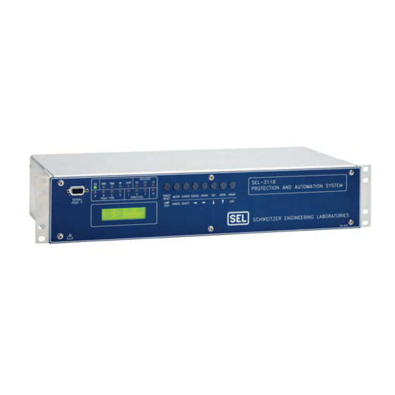
Schweitzer Engineering Laboratories SEL-311B Instruction Manual (602 pages)
PROTECTION AND AUTOMATION SYSTEM
Brand:
Schweitzer Engineering Laboratories
| Category:
Protection Device
| Size: 7 MB
Table of Contents
Table of Contents
9
Introduction and Specifications
11
SEL-311B Relay Models
11
Instruction Manual Sections Overview
11
Applications
14
AC/DC Connections
14
Figure 1.2: SEL-311B Relay Inputs, Outputs, and Communications Ports
15
Communications Connections
16
Figure 1.3: SEL-311B Relay Communications Connections Examples
16
Figure 1.4: SEL-311B Relay Communications Connections Examples (Continued)
17
Relay Specifications
18
General Specifications
18
Processing Specifications
20
Relay Element Settings Ranges and Accuracies
21
Table of Contents
25
Section 2: Installation
27
Relay Mounting
27
Front- and Rear-Panel Diagrams
28
Making Rear-Panel Connections
31
Wire-Alike Screw Terminal Connections
31
Power Supply
31
Output Contacts
31
Optoisolated Inputs
31
Current Transformer Inputs
31
Potential Transformer Inputs
32
Serial Ports
32
IRIG-B Time-Code Input
32
Table 2.1: Communication Cables to Connect the SEL-311B Relay to Other Devices
33
Circuit Board Connections
37
Accessing the Relay Circuit Boards
37
Output Contact Jumpers
39
Extra Alarm" Output Contact Control Jumper
39
Table 2.2: Output Contact Jumpers and Corresponding Output Contacts
39
Table 2.3: Move Jumper JMP23 to Select Extra Alarm
40
Password and Breaker Jumpers
41
EIA-232 Serial Port Voltage Jumpers
41
Table 2.4: Password and Breaker Jumper Operation
41
Table 2.5: EIA-232 Serial Port Voltage Jumper Positions for Standard Relay Shipments
41
Clock Battery
42
Section 3: Distance, Overcurrent, Voltage, and Synchronism Check Elements
43
Distance Elements
45
Section 3: Distance, Overcurrent, Voltage, and Synchronism Check Elements
45
Phase Distance Elements
45
Ground Distance Elements
54
Distance Element Operating Time Curves at Nominal Frequency
57
Additional Distance Element Supervision
59
Zone 1 Extension
59
Zone Time Delay Elements
60
Phase Instantaneous/Definite-Time Overcurrent Elements
61
Residual Ground Instantaneous/Definite-Time Overcurrent Elements
65
Negative-Sequence Instantaneous/Definite-Time Overcurrent Elements
67
Time-Overcurrent Elements
68
Phase Time-Overcurrent Elements
68
Residual Ground Time-Overcurrent Element
72
Negative-Sequence Time-Overcurrent Element
74
Voltage Elements
75
Voltage Values
75
Voltage Element Settings
76
Voltage Element Operation
79
Synchronism Check Elements
80
Fixed Angle Synchronism Check
80
Dynamic Synchronism Check
80
Synchronism Check Elements Settings
81
Synchronism Check Elements Voltage Inputs
84
Synchronism Check Elements Operation
84
Synchronism Check Applications for Automatic Reclosing and Manual Closing
90
Section 4: Loss-Of-Potential, Ccvt Transient Detection, Load-Encroachment, and Directional Element Logic
91
Loss-Of-Potential Logic
93
Setting ELOP = y or Y1
94
Setting ELOP = y
95
Setting ELOP = N
95
Section 4: Loss-Of-Potential, Ccvt Transient Detection, Load-Encroachment, and Directional Element Logic
93
CCVT Transient Detection Logic
95
Load-Encroachment Logic
96
Settings Ranges
98
Load-Encroachment Setting Example
98
Convert Power Factors to Equivalent Load Angles
99
Use SEL-321 Relay Application Guide for the SEL-311B Relay
100
Directional Element Enables
102
Best Choice Ground Directional Logic
102
Directional Elements
102
Directional Element Routing
103
Internal Enables
111
Directional Elements
112
Directional Element Routing
112
Directional Control Settings
114
Settings Made Automatically
114
Section 5: Trip and Target Logic
123
Section 5: Trip and Target Logic
125
Trip Logic
125
Set Trip
126
Unlatch Trip
127
Factory Settings Example (Using Setting TR)
128
Additional Settings Examples
129
Program an Output Contact for Tripping
129
Switch-Onto-Fault (SOTF) Trip Logic
130
Three-Pole Open Logic
131
Circuit Breaker Operated Switch-Onto-Fault Logic
132
Close Bus Operated Switch-Onto-Fault Logic
133
Switch-Onto-Fault Logic Output (SOTFE)
133
Switch-Onto-Fault Trip Logic Trip Setting (TRSOTF)
133
Additional Target LED Information
134
Target Reset/Lamp Test Front-Panel Pushbutton
136
Section 6: Close and Reclose Logic
139
Close Logic
141
Set Close
142
Unlatch Close
143
Factory Settings Example
143
Defeat the Close Logic
144
Circuit Breaker Status
144
Program an Output Contact for Closing
144
Overview
141
Section 6: Close and Reclose Logic
141
Reclose Supervision Logic
145
Settings and General Operation
148
Settings Example
150
Additional Settings Example 1
150
Additional Settings Example 2
152
Reclosing Relay
152
Reclosing Relay States and General Operation
153
Reclosing Relay States after a Settings or Setting Group Change
154
Defeat the Reclosing Relay
155
Reclosing Relay Timer Settings
156
Reclosing Relay Shot Counter
159
Reclose Initiate and Reclose Initiate Supervision Settings (79RI and 79RIS, Respectively)
160
Drive-To-Lockout and Drive-To-Last Shot Settings (79DTL and 79DLS, Respectively)
162
Skip Shot and Stall Open Interval Timing Settings (79SKP and 79STL, Respectively)
164
Block Reset Timing Setting (79BRS)
166
Sequence Coordination Setting (79SEQ)
167
Table of Contents
169
Section 7: Inputs, Outputs, Timers, and Other
173
Control Logic
173
Optoisolated Inputs
173
Input Debounce Timers
174
Input Functions
174
Settings Example 1
175
Local Control Switches
177
Local Control Switch Types
178
Settings Examples
180
Additional Local Control Switch Application Ideas
181
Local Control Switch States Retained
181
Remote Control Switches
182
Remote Bit Application Ideas
183
Remote Bit States Not Retained When Power Is Lost
183
Remote Bit States Retained When Settings Changed or Active Setting Group Changed
183
Latch Control Switches
183
Latch Control Switch Application Ideas
185
Reclosing Relay Enable/Disable Setting Example
185
Latch Control Switch States Retained
189
Reset Latch Bits for Active Setting Group Change
189
Note: Make Latch Control Switch Settings with Care
190
Multiple Setting Groups
192
Active Setting Group Indication
192
Selecting the Active Setting Group
192
Operation of SEL OGIC ® Control Equation Settings SS1 through SS6
193
Operation of Serial Port GROUP Command and Front-Panel GROUP Pushbutton
193
Relay Disabled Momentarily During Active Setting Group Change
194
Active Setting Group Switching Example 1
194
Active Setting Group Switching Example 2
197
Active Setting Group Retained
200
Note: Make Active Setting Group Switching Settings with Care
201
SEL OGIC Control Equation Variables/Timers
201
Settings Example
203
Additional Settings Example 1
203
Additional Settings Example 2
204
Timers Reset When Power Is Lost, Settings Are Changed, or Active Setting Group Is Changed
204
Output Contacts
205
Factory Settings Example
205
Operation of Output Contacts for Different Output Contact Types
205
Rotating Default Display (Only on Models with LCD)
207
Traditional Indicating Panel Lights
208
Traditional Indicating Panel Lights Replaced with Rotating Default Display
208
Section 8: Breaker Monitor and Metering Functions
221
Breaker Monitor
223
Breaker Monitor Setting Example
226
Breaker Monitor Operation Example
229
Breaker Monitor Output
234
View or Reset Breaker Monitor Information
234
Determination of Relay-Initiated Trips and Externally Initiated Trips
235
Introduction
223
Section 8: Breaker Monitor and Metering Functions
223
Station DC Battery Monitor
236
DC Under- and Overvoltage Elements
237
Create Desired Logic for DC Under- and Overvoltage Alarming
237
Additional Application
239
View Station DC Battery Voltage
240
Analyze Station DC Battery Voltage
240
Operation of Station DC Battery Monitor When AC Voltage Is Powering the Relay
241
Demand Metering
241
Comparison of Thermal and Rolling Demand Meters
242
Demand Meter Settings
246
Demand Current Logic Output Application-Raise Pickup for Unbalance Current
248
View or Reset Demand Metering Information
250
Demand Metering Updating and Storage
250
Energy Metering
250
View or Reset Energy Metering Information
250
Energy Metering Updating and Storage
251
Maximum/Minimum Metering
251
View or Reset Maximum/Minimum Metering Information
251
Maximum/Minimum Metering Updating and Storage
252
Section 9: Setting the Relay
253
Introduction
255
Section 9: Setting the Relay
255
Settings Changes Via the Front Panel
255
Settings Changes Via the Serial Port
256
Ogic
261
Current Transformer Ratios
280
Line Settings
280
Enable Settings
280
Other System Parameters
281
Settings Sheets
281
Section 10: Serial Port Communications and Commands
305
Introduction
307
Irig-B
307
SEL-311B to Computer
309
SEL-311B to Modem or Other DCE
309
SEL-311B to SEL-PRTU
310
Section 10: Serial Port Communications and Commands
307
Communications Protocols
311
Hardware Protocol
311
Software Protocols
311
Serial Port Access Levels
314
Access Level 0
314
Access Level 1
314
Access Level B
315
Access Level 2
315
Command Summary
316
Access Level 1 Commands
318
Access Level 2 Commands
342
SEL-311B Relay Command Summary
345
Section 11: Front-Panel Interface (Only on Models with Lcd)
347
Front-Panel Pushbutton Operation
349
Overview
349
Primary Functions
350
Front-Panel Password Security
350
Secondary Functions
352
Introduction
349
Section 11: Front-Panel Interface (Only on Models with Lcd)
349
Functions Unique to the Front-Panel Interface
354
Reclosing Relay Shot Counter Screen
354
Local Control
356
View Local Control (with Example Settings)
357
Operate Local Control (with Example Settings)
358
Local Control State Retained When Relay Deenergized
359
Rotating Default Display
359
Scroll Lock Control of Front Panel LCD
362
Stop Scrolling (Lock)
363
Restart Scrolling (Unlock)
363
Single Step
363
Exit
363
Cancel
363
Additional Rotating Default Display Example
363
Section 12: Standard Event Reports and Ser
365
Introduction
367
Event Report Length (Settings LER and PRE)
367
Standard Event Report Triggering
368
Event Summary
369
Retrieving Full-Length Standard Event Reports
372
Compressed ASCII Event Reports
373
Filtered and Unfiltered Event Reports
373
Clearing Standard Event Report Buffer
374
Standard Event Report Column Definitions
374
Section 12: Standard Event Reports and Ser
367
Example Standard 15-Cycle Event Report
386
Sequential Events Recorder (SER) Report
395
SER Triggering
395
Making SER Trigger Settings
395
Clearing SER Report
397
Section 13: Testing and Troubleshooting
399
Introduction
401
Section 13: Testing and Troubleshooting
401
Testing Philosophy
401
Acceptance Testing
401
Commissioning Testing
401
Maintenance Testing
402
Test Features Provided by the Relay
403
Low-Level Test Interface
404
Test Methods
405
Relay Testing
406
Equipment Required
406
Checkout Procedure
406
Output Contact Explanation
410
Target LED Explanation
410
Front Panel LCD Explanation
411
Test Setup
411
Test Source Connections
411
Serial Communication Equipment Connections
416
Test Procedures
417
Overcurrent Elements
417
Phase Mho Distance Elements
429
Ground Mho Distance Elements
435
Relay Self-Tests
443
Relay Troubleshooting
446
Inspection Procedure
446
Troubleshooting Procedure
446
Factory Assistance
447
Relay Calibration
447
Section 14: Application Settings for Sel-221 Series
449
Relays
451
Section 14: Application Settings for Sel-221 Series
451
Application Settings
452
Application Settings
484
Convert SEL-221C Primary Quantities to SEL-311B Secondary Quantities
484
Convert SEL-221C Relay Settings to SEL-311B Relay Settings
484
Convert SEL-221-16 Primary Quantities to SEL-311B Secondary Quantities
502
Convert SEL-221-16 Relay Settings to SEL-311B Relay Settings
502
Application Settings
509
Convert SEL-2PG10 Primary Quantities to SEL-311B Secondary Quantities
514
Convert SEL-2PG10 Relay Settings to SEL-311B Relay Settings
514
Table of Contents
523
Appendix A: Firmware Versions
527
Appendix B: Firmware Upgrade Instructions
529
Firmware (Flash) Upgrade Instructions
529
Important Note Regarding Settings
529
Required Equipment
529
Upgrade Procedure
529
Appendix C: Sel Distributed Port Switch Protocol
535
Settings
535
Operation
535
Appendix D: Configuration, Fast Meter, and Fast
537
Operate Commands
537
Introduction
537
Message Lists
537
Binary Message List
537
ASCII Configuration Message List
538
Message Definitions
538
A5C0 Relay Definition Block
538
A5C1 Fast Meter Configuration Block
539
A5D1 Fast Meter Data Block
540
A5C2/A5C3 Demand/Peak Demand Fast Meter Configuration Messages
540
A5D2/A5D3 Demand/Peak Demand Fast Meter Message
543
A5B9 Fast Meter Status Acknowledge Message
543
A5CE Fast Operate Configuration Block
543
A5E0 Fast Operate Remote Bit Control
545
A5E3 Fast Operate Breaker Control
546
A5CD Fast Operate Reset Definition Block
546
A5ED Fast Operate Reset Command
546
ID Message
547
DNA Message
547
BNA Message
549
SNS Message
549
Appendix E: Compressed Ascii Commands
551
Introduction
551
CASCII Command-SEL-311B
552
CSTATUS Command-SEL-311B
554
CHISTORY Command-SEL-311B
555
CEVENT Command-SEL-311B
555
Appendix F: Setting Negative-Sequence
559
Overcurrent Elements
559
Appendix G: Setting Sel Ogic ® Control Equations
561
Relay Word Bits
561
Relay Word Bit Operation Example-Phase Time-Overcurrent Element 51PT
561
Sel Ogic
561
Appendix H: Distributed Network Protocol (Dnp)
571
Overview
571
Configuration
571
Data-Link Operation
572
Data Access Method
572
Device Profile
573
Object Table
576
Data Map
579
Appendix I: Mirrored Bits™ Communications
587
Overview
587
Operation
587
Message Transmission
587
Message Decoding and Integrity Checks
587
Mirrored Bits
587
Settings
590
Appendix J: Unsolicited Fast Ser Protocol
593
Introduction
593
Make Sequential Events Recorder (SER) Settings with Care
593
Recommended Message Usage
593
01-Function Code: Enable Unsolicited Data Transfer, Sent from Master to Relay
594
02-Function Code: Disable Unsolicited Data Transfer, Sent from Master to Relay
595
18-Function: Unsolicited Fast SER Response, Sent from Relay to Master
595
Acknowledge Message Sent from Master to Relay, and from Relay to Master
597
Advertisement
Advertisement
Related Products
Schweitzer Engineering Laboratories SEL-311L
Schweitzer Engineering Laboratories SEL-311A
Schweitzer Engineering Laboratories SEL-311C
Schweitzer Engineering Laboratories SEL-3022
Schweitzer Engineering Laboratories SEL-321-5
Schweitzer Engineering Laboratories SEL-321-2
Schweitzer Engineering Laboratories SEL-321
Schweitzer Engineering Laboratories SEL-351S
Schweitzer Engineering Laboratories SEL-387-6
Schweitzer Engineering Laboratories SEL-351-3
Schweitzer Engineering Laboratories Categories
Relays
Computer Hardware
Transceiver
Protection Device
Measuring Instruments
More Schweitzer Engineering Laboratories Manuals
Login
Sign In
OR
Sign in with Facebook
Sign in with Google
Upload manual
Upload from disk
Upload from URL