
Related Manuals for Schweitzer Engineering Laboratories SEL-311B


Summary of Contents for Schweitzer Engineering Laboratories SEL-311B
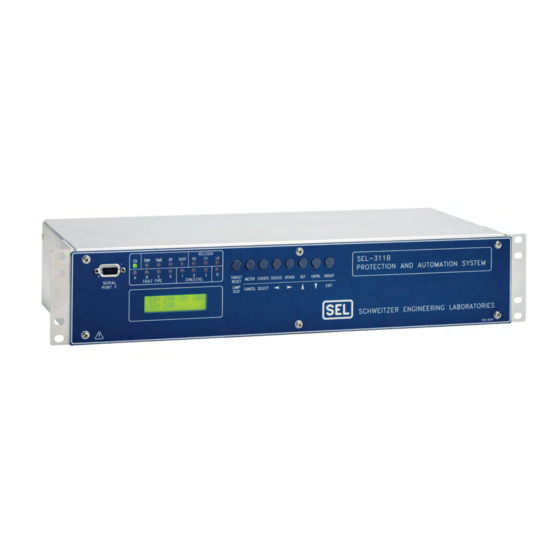
- Page 1 SEL-311B PROTECTION AND AUTOMATION SYSTEM INSTRUCTION MANUAL SCHWEITZER ENGINEERING LABORATORIES 2350 NE HOPKINS COURT PULLMAN, WA USA 99163-5603 TEL: (509) 332-1890 FAX: (509) 332-7990...
- Page 2 You may not copy, alter, disassemble, or reverse-engineer the software. You may not provide the software to any third party. All brand or product names appearing in this document are the trademark or registered trademark of their respective holders. Schweitzer Engineering Laboratories, SEL , Connectorized, Job Done, SEL-PROFILE,...
- Page 3 - Updated Event Report Parameters section in the Settings Sheets. - Updated Optoisolated Input Timers section in the Settings Sheets. - Added ELAT and EDP settings in the Other Enable Settings section in the Settings Sheets. Date Code 20011205 Manual Change Information SEL-311B Instruction Manual...
- Page 4 Appendix D: - Updated A5C0 Relay Definition Block section. - Updated information in ID Message and DNA Message sections. Appendix H: - Updated SEL-311B-Wye DNP Data Map table. Appendix J: - Added Appendix J: Unsolicited Fast SER Protocol. 20010625 Section 3: - Corrected Table 3.7.
- Page 5 - Added Warning statement to change default passwords to private passwords at relay installation. Appendix H: - Updated first row of Table H.3. - Correctly identify binary output point 23 in the Relay Summary Event Data subsection. 20000818 New Manual Release. Date Code 20011205 Manual Change Information SEL-311B Instruction Manual...
- Page 7 ® Appendix G: Setting SEL Control Equations OGIC Appendix H: Distributed Network Protocol (DNP) 3.00 Appendix I: M ™ Communications IRRORED Appendix J: Unsolicited Fast SER Protocol SEL-311B RELAY COMMAND SUMMARY Date Code 20011205 Table of Contents SEL-311B Instruction Manual...
-
Page 9: Table Of Contents
Figure 1.1: SEL-311B Relay Transmission Line Protection with M ™, Reclosing, IRRORED and Synch Check......................1-4 Figure 1.2: SEL-311B Relay Inputs, Outputs, and Communications Ports ..........1-5 Figure 1.3: SEL-311B Relay Communications Connections Examples..........1-6 Figure 1.4: SEL-311B Relay Communications Connections Examples (Continued) ......1-7 Date Code 20011205... -
Page 11: Introduction And Specifications
ODELS This instruction manual covers all SEL-311B Relay models. The SEL-311B Relay is available as a horizontal rack-mount unit, and as a horizontal or vertical panel-mount unit. The vertical relays use the same rear panels as the horizontal models in Figure 2.2 through Figure 2.4. - Page 12 Section 9: Setting the Relay explains how to enter settings and also contains the following setting reference information: · Time-overcurrent curves (5 US and 5 IEC curves) · Relay Word bit table and definitions (Relay Word bits are used in SEL control OGIC equation settings) Introduction and Specifications Date Code 20011205 SEL-311B Instruction Manual...
- Page 13 SER, text OGIC label, and serial port settings The Settings Sheets can be photocopied and filled out to set the SEL-311B Relay. Note that these sheets correspond to the serial port SET commands listed in Table 9.1.
-
Page 14: Applications
Appendix I: M ™ Communciations IRRORED · Appendix J: SEL-311B Unsolicited SER Protocol SEL-311B Relay Command Summary briefly describes the serial port commands that are described in detail in Section 10: Serial Port Communications and Commands. PPLICATIONS SEL-311B SEL-311B IRRORED... -
Page 15: Figure 1.2: Sel-311B Relay Inputs, Outputs, And Communications Ports
For installation in systems with drawings designed for SEL-311B Relays, use the alphanumeric terminal labels. See Figure 2.2 through Figure 2.4 for rear-panel drawings. Figure 1.2: SEL-311B Relay Inputs, Outputs, and Communications Ports Date Code 20011205 Introduction and Specifications SEL-311B Instruction Manual... -
Page 16: Communications Connections
OMMUNICATIONS ONNECTIONS See Port Connector and Communications Cables in Section 10: Serial Port Communications and Commands for more communications connection information. Figure 1.3: SEL-311B Relay Communications Connections Examples Introduction and Specifications Date Code 20011205 SEL-311B Instruction Manual... -
Page 17: Figure 1.4: Sel-311B Relay Communications Connections Examples (Continued)
SEL-311B Relay SEL-311B Relay SEL-2800 SEL-2800 SEL-2800 SEL-2505 Transformer Alarms SEL-2800 SEL-2800 IN101 SEL-2100 Relay Protection Logic Processor M311B004 Figure 1.4: SEL-311B Relay Communications Connections Examples (Continued) Date Code 20011205 Introduction and Specifications SEL-311B Instruction Manual... -
Page 18: Relay Specifications
ELAY PECIFICATIONS Important: Do not use the following specification information to order an SEL-311B Relay. Refer to the actual ordering information sheets. General Specifications Terminal Connections: Rear Screw-Terminal Tightening Torque Terminal Block Minimum: 8-in-lb (0.9 Nm) Maximum: 12-in-lb (1.4 Nm) ®... - Page 19 Relay accepts demodulated IRIG-B time-code input at Port 2. Time-Code Input: Relay time is synchronized to within ±5 ms of time-source input. Operating Temperature Range: -40° to +85°C (-40° to +185°F) Note: LCD contrast impaired for temperatures below -20°C. Date Code 20011205 Introduction and Specifications SEL-311B Instruction Manual...
-
Page 20: Processing Specifications
One cycle cosine after low-pass analog filtering. Net filtering (analog plus digital) rejects dc and all harmonics greater than the fundamental. Protection and Control Processing 4 times per power system cycle. 1-10 Introduction and Specifications Date Code 20011205 SEL-311B Instruction Manual... -
Page 21: Relay Element Settings Ranges And Accuracies
±0.01 A and ±3% of setting (1 A nominal) Transient Overreach: < 5% of pickup Max. Operating Time: See pickup and reset time curves in Figure 3.14 and Figure 3.15 Date Code 20011205 Introduction and Specifications 1-11 SEL-311B Instruction Manual... - Page 22 Time Dial Range: 0.50–15.00, 0.01 steps (US) 0.05–1.00, 0.01 steps (IEC) Curve Timing Accuracy: ±1.50 cycles and ±4% of curve time for current between 2 and 30 multiples of pickup 1-12 Introduction and Specifications Date Code 20011205 SEL-311B Instruction Manual...
- Page 23 < 5% of pickup Synchronism-Check Elements Slip Frequency Pickup Range: 0.005–0.500 Hz, 0.001 Hz steps Slip Frequency Pickup Accuracy: ±0.003 Hz Phase Angle Range: 0–80°, 1° steps Phase Angle Accuracy: ±4° Date Code 20011205 Introduction and Specifications 1-13 SEL-311B Instruction Manual...
- Page 25 Figure 2.5: SEL-311B Relay Provides Distance and Overcurrent Protection, Reclosing, and Synch Check for a Transmission Line ................2-8 Figure 2.6: SEL-311B Relay Provides Distance and Overcurrent Protection, and Reclosing for a Transmission Line (Current Polarization Source Connected to Channel IP) ....2-9 Figure 2.7: SEL-311B Line Protection Through a Delta-Wye Transformer Using Compensator...
-
Page 27: Section 2: Installation
SECTION 2: INSTALLATION ELAY OUNTING Figure 2.1: SEL-311B Relay Dimensions and Panel-Mount Cutout Date Code 20011205 Installation SEL-311B Instruction Manual... -
Page 28: Front- And Rear-Panel Diagrams
RONT ANEL IAGRAMS Figure 2.2: SEL-311B Relay Front- and Rear-Panel Drawings—Models 0311B00H2 (Rack) and 0311B0032 (Panel) Installation Date Code 20011205 SEL-311B Instruction Manual... - Page 29 Figure 2.3: SEL-311B Relay Front- and Rear-Panel Drawings—Model 0311B0041 Date Code 20011205 Installation SEL-311B Instruction Manual...
- Page 30 ® Figure 2.4: SEL-311B Relay Connectorized Rear-Panel Drawing Installation Date Code 20011205 SEL-311B Instruction Manual...
-
Page 31: Making Rear-Panel Connections
SEL-221 terminal numbers are shown on the rear-panel wiring connections for those models. A properly programmed SEL-311B Relay may be installed in place of an SEL-221 Relay with no changes to the terminal numbers in a user’s wiring diagram. -
Page 32: Potential Transformer Inputs
All ports are independent—you can communicate to any combination simultaneously. Serial Port 1 on all the SEL-311B Relay models is an EIA-485 port (4-wire). The Serial Port 1 plug-in connector accepts wire size AWG 24 to 12. Strip the wires 0.31 inches (8 mm) and install with a small slotted-tip screwdriver. -
Page 33: Table 2.1: Communication Cables To Connect The Sel-311B Relay To Other Devices
A demodulated IRIG-B time code can be input into Serial Port 2 on any of the SEL-311B Relay models (see Table 10.1) by connecting Serial Port 2 of the SEL-311B Relay to an SEL-2020 with Cable C273A. - Page 34 Voltage Channel VS is used in voltage and synchronism check elements and voltage metering. Current Channel IP does not need to be connected. Channel IP provides current for current polarized directional elements. Figure 2.5: SEL-311B Relay Provides Distance and Overcurrent Protection, Reclosing, and Synch Check for a Transmission Line Installation...
- Page 35 In this example, current Channel IP provides current polarization for a directional element used to control ground elements. Figure 2.6: SEL-311B Relay Provides Distance and Overcurrent Protection, and Reclosing for a Transmission Line (Current Polarization Source Connected to Channel IP)
- Page 36 Use compensator distance elements for line protection through a delta-wye transformer. Voltage VS does not need to be connected. Figure 2.7: SEL-311B Line Protection Through a Delta-Wye Transformer Using Compensator Distance Elements 2-10 Installation Date Code 20011205 SEL-311B Instruction Manual...
-
Page 37: Circuit Board Connections
When finished, slide the drawout assembly into the relay chassis. Reconnect the cables removed in step 4. Replace the relay front-panel cover. Replace any cables previously connected to serial ports. Reenergize the relay. Date Code 20011205 Installation 2-11 SEL-311B Instruction Manual... - Page 38 Figure 2.8: Jumper, Connector, and Major Component Locations on the SEL-311B Relay Main Board 2-12 Installation Date Code 20011205 SEL-311B Instruction Manual...
-
Page 39: Output Contact Jumpers
Figure 2.8 “Extra Alarm” Output Contact Control Jumper All the SEL-311B Relays have dedicated alarm output contacts (labeled ALARM—see Figure 2.2 and Figure 2.3). Often more than one alarm output contact is needed for such applications as local or remote annunciation, backup schemes, etc. -
Page 40: Table 2.3: Move Jumper Jmp23 To Select Extra Alarm
Contact Jumpers). Thus, the dedicated ALARM output contact and the “extra alarm” output contact can be configured as the same output contact type if desired (e.g., both can be configured as “b” type output contacts). 2-14 Installation Date Code 20011205 SEL-311B Instruction Manual... -
Page 41: Password And Breaker Jumpers
Table 2.5: EIA-232 Serial Port Voltage Jumper Positions for Standard Relay Shipments EIA-232 Serial Port 2 EIA-232 Serial Port 3 (rear panel) (rear panel) Reference Figure JMP2 = OFF JMP1 = OFF Figure 2.8 Date Code 20011205 Installation 2-15 SEL-311B Instruction Manual... -
Page 42: Clock Battery
(+) of the battery faces up. Reassemble the relay as described in Accessing the Relay Circuit Boards. Set the relay date and time via serial communications port or front panel (see Section 10: Serial Port Communications and Commands or Section 11: Front-Panel Interface). 2-16 Installation Date Code 20011205 SEL-311B Instruction Manual... - Page 43 Table 3.7: Voltage Values Used by Voltage Elements ................3-32 Table 3.8: Voltage Elements Settings and Settings Ranges..............3-32 Table 3.9: Synchronism Check Elements Settings and Settings Ranges ..........3-37 Date Code 20011205 Distance, Overcurrent, Voltage, and Synchronism Check Elements SEL-311B Instruction Manual...
- Page 44 Figure 3.11: Zone 1 Extension Logic......................3-16 Figure 3.12: Zone Timing Elements .......................3-17 Figure 3.13: Levels 1 through 3 Phase Instantaneous/Definite-Time Overcurrent Elements ....3-19 Figure 3.14: SEL-311B Relay Nondirectional Instantaneous Overcurrent Element Pickup Time Curve ..........................3-20 Figure 3.15: SEL-311B Relay Nondirectional Instantaneous Overcurrent Element Reset Time Curve ..........................3-21...
-
Page 45: Distance Elements
LEMENTS Phase Distance Elements The SEL-311B Relay has three independent zones of mho phase distance protection. All zones are independently set. Zones 1 and 2 are fixed to operate in the forward direction only. Zone 3 can be set to operate either forward or reverse. The phase distance elements use positive- sequence voltage polarization for security and to create an expanded mho characteristic. - Page 46 In the compensator distance three-phase element, the polarizing voltage is (-jV - 0.25 • V mem) and the line drop compensated voltage is (V - Z • I Distance, Overcurrent, Voltage, Date Code 20011205 and Synchronism Check Elements SEL-311B Instruction Manual...
- Page 47 (q) > 0 (Z • I - V) Vmem I • R I • Z source M311B034 Forward Internal Fault Figure 3.1: Positive-Sequence Polarized Mho Element Date Code 20011205 Distance, Overcurrent, Voltage, and Synchronism Check Elements SEL-311B Instruction Manual...
- Page 48 (q) < 0 Fault Near Balance Point Internal Fault Note: V , and V are internal element voltages, not system voltages. M311B035 Figure 3.2: Compensator-Distance Phase-to-Phase Element Operation Distance, Overcurrent, Voltage, Date Code 20011205 and Synchronism Check Elements SEL-311B Instruction Manual...
- Page 49 Calculate the total primary impedance as the sum of the per-unit transformer and line impedances, then convert from per-unit to actual primary impedance at the protected bus voltage. The Date Code 20011205 Distance, Overcurrent, Voltage, and Synchronism Check Elements SEL-311B Instruction Manual...
- Page 50 ±0.01 A and ±3% of setting (1 A nominal) Transient Overreach: < 5% of pickup Max. Operating Time: See pickup and reset time curves in Figure 3.14 and Figure 3.15. Distance, Overcurrent, Voltage, Date Code 20011205 and Synchronism Check Elements SEL-311B Instruction Manual...
- Page 51 From Figure 4.14 „ From Figure 4.1 ‚ From Figure 4.15 … From Figure 3.11 ƒ From Figure 4.2 Figure 3.4: Zone 1 Phase Distance Logic Date Code 20011205 Distance, Overcurrent, Voltage, and Synchronism Check Elements SEL-311B Instruction Manual...
- Page 52 Note 2: ABC2 and PP2 are compensator distance element calculations. From Figure 4.14 ƒ From Figure 4.1 ‚ From Figure 4.15 Figure 3.5: Zone 2 Phase Distance Logic Distance, Overcurrent, Voltage, Date Code 20011205 and Synchronism Check Elements SEL-311B Instruction Manual...
- Page 53 Note 2: ABC3 and PP3 are compensator distance element calculations. From Figure 4.14 ƒ From Figure 4.1 ‚ From Figure 4.15 Figure 3.6: Zone 3 Phase Distance Logic Date Code 20011205 Distance, Overcurrent, Voltage, and Synchronism Check Elements SEL-311B Instruction Manual...
-
Page 54: Ground Distance Elements
Ground Distance Elements The SEL-311B Relay has three independent zones of mho ground distance protection. All zones are independently set. Zones 1 and 2 are forward direction only, and Zone 3 can be set either forward or reverse. The mho ground distance elements use positive-sequence voltage polarization for security and to create an expanded mho characteristic. - Page 55 From Figure 4.12 „ From Figure 4.1 ‚ From Figure 4.2 … From Figure 3.11 ƒ From Figure 5.3 Figure 3.7: Zone 1 Mho Ground Distance Logic Date Code 20011205 Distance, Overcurrent, Voltage, 3-11 and Synchronism Check Elements SEL-311B Instruction Manual...
- Page 56 Z2MG = Zone 2 Distance Setting From Figure 4.12 ƒ From Figure 4.1 ‚ From Figure 5.3 Figure 3.8: Zone 2 Mho Ground Distance Logic 3-12 Distance, Overcurrent, Voltage, Date Code 20011205 and Synchronism Check Elements SEL-311B Instruction Manual...
-
Page 57: Distance Element Operating Time Curves At Nominal Frequency
Figure 3.9: Zone 3 Mho Ground Distance Logic Distance Element Operating Time Curves at Nominal Frequency Figure 3.10 shows operating times for the SEL-311B Relay distance elements. The diagrams show operating times at each test point. Operating times include output contact closure time. - Page 58 SEL-311B Phase Mho Operating Times Phase-to-Phase Faults 1.75 1.25 SIR = 0.1 SIR = 1.0 SIR = 10.0 SIR = 30.0 0.75 0.25 Fault Location in Percent of Set Reach SEL-311B Mho Ground Operating Times Single-Line-to-Ground Faults 2.25 1.75 SIR = 0.1 1.25...
-
Page 59: Additional Distance Element Supervision
Additional Distance Element Supervision The SEL-311B uses Relay Word bit VPOLV for positive-sequence memory supervision of mho and quadrilateral characteristics. VPOLV asserts when the memorized positive-sequence polarizing voltage is greater than 1 Volt. Mho-phase and ground distance elements are supervised with Fault Identification Selection (FIDS) logic. -
Page 60: Zone Time Delay Elements
Figure 3.11: Zone 1 Extension Logic Zone Time Delay Elements The SEL-311B Relay supports two philosophies of zone timing: independent or common timing (see Figure 3.12). For the independent timing mode, the phase and ground distance elements drive separate timers for each zone. For the common mode, the phase and ground distance elements both drive a common timer. -
Page 61: Phase Instantaneous/Definite-Time Overcurrent Elements
E50P enable setting, as shown in Figure 3.13. All phase instantaneous/definite-time overcurrent elements are available for use in any user-defined tripping or control scheme. Date Code 20011205 Distance, Overcurrent, Voltage, 3-17 and Synchronism Check Elements SEL-311B Instruction Manual... - Page 62 Ideally, set 50P1P > 50P2P > 50P3P so that overcurrent elements will display in an organized fashion in event reports (see Figure 3.13 and Table 12.3). 3-18 Distance, Overcurrent, Voltage, Date Code 20011205 and Synchronism Check Elements SEL-311B Instruction Manual...
- Page 63 1 (e.g., 67P1TC = 1) for the factory default settings. See SHO Command (Show/View Settings) in Section 10: Serial Port Communications and Commands for a list of the factory default settings. Date Code 20011205 Distance, Overcurrent, Voltage, 3-19 and Synchronism Check Elements SEL-311B Instruction Manual...
- Page 64 Figure 3.14 and Figure 3.15 show pickup and reset time curves applicable to all nondirectional instantaneous overcurrent elements in the SEL-311B Relay (60 Hz or 50 Hz relays). These times do not include output contact operating time and, thus, are accurate for determining element operation time for use in internal SEL control equations.
-
Page 65: Residual Ground Instantaneous/Definite-Time Overcurrent Elements
Maximum Minimum Applied Current (Multiples of Pickup Setting) Figure 3.15: SEL-311B Relay Nondirectional Instantaneous Overcurrent Element Reset Time Curve Residual Ground Instantaneous/Definite-Time Overcurrent Elements Three levels of residual ground instantaneous/definite-time overcurrent elements are available. The different levels are enabled with the E50G enable setting, as shown in Figure 3.16. - Page 66 OFF, 0.05–20.00 A secondary (1 A nominal phase current inputs, IA, IB, IC) Setting range for definite-time settings 67G1D through 67G3D: 0.00–16000.00 cycles, in 0.25-cycle steps 3-22 Distance, Overcurrent, Voltage, Date Code 20011205 and Synchronism Check Elements SEL-311B Instruction Manual...
-
Page 67: Negative-Sequence Instantaneous/Definite-Time Overcurrent Elements
±0.01 A secondary and ±3% of setting (1 A nominal phase current inputs, IA, IB, IC) ±0.25 cycles and ±0.1% of setting Timer: Transient Overreach: < 5% of setting Pickup and Reset Time Curves See Figure 3.14 and Figure 3.15. Date Code 20011205 Distance, Overcurrent, Voltage, 3-23 and Synchronism Check Elements SEL-311B Instruction Manual... -
Page 68: Time-Overcurrent Elements
Table 3.2: Available Phase Time-Overcurrent Elements Time-Overcurrent Enabled with Element Setting Operating Current See Figure 51PT E51P = Y , maximum of A-, B-, and Figure 3.18 C-phase currents 3-24 Distance, Overcurrent, Voltage, Date Code 20011205 and Synchronism Check Elements SEL-311B Instruction Manual... - Page 69 (e.g., 51PTC) cannot be set directly to OGIC logical 0. See Section 9: Setting the Relay for additional time-overcurrent element setting information. Figure 3.18: Phase Time-Overcurrent Element 51PT Date Code 20011205 Distance, Overcurrent, Voltage, 3-25 and Synchronism Check Elements SEL-311B Instruction Manual...
- Page 70 > pickup setting 51PP and the phase time-overcurrent element is timing, but not yet timed out on its curve £ pickup setting 51PP = 0 (logical 0), if I 3-26 Distance, Overcurrent, Voltage, Date Code 20011205 and Synchronism Check Elements SEL-311B Instruction Manual...
- Page 71 51PTC = IN105 Input IN105 deasserted (51PTC = IN105 = logical 0): The Torque Control Switch opens and phase time-overcurrent element 51PT is defeated and nonoperational, regardless of any other setting. Date Code 20011205 Distance, Overcurrent, Voltage, 3-27 and Synchronism Check Elements SEL-311B Instruction Manual...
-
Page 72: Residual Ground Time-Overcurrent Element
Phase Time-Overcurrent Elements subsection, substituting residual ground current I = 3I ) for maximum phase current I and substituting like settings and Relay Word bits. 3-28 Distance, Overcurrent, Voltage, Date Code 20011205 and Synchronism Check Elements SEL-311B Instruction Manual... - Page 73 (e.g., 51GTC) cannot be set directly to OGIC logical 0. See Section 9: Setting the Relay for additional time-overcurrent element settings information. Date Code 20011205 Distance, Overcurrent, Voltage, 3-29 and Synchronism Check Elements SEL-311B Instruction Manual...
-
Page 74: Negative-Sequence Time-Overcurrent Element
= 1 Ð -120°] for maximum phase current I and like settings and Relay Word bits. Figure 3.20: Negative-Sequence Time-Overcurrent Element 51QT IMPORTANT: See Appendix F for information on setting negative-sequence overcurrent elements. 3-30 Distance, Overcurrent, Voltage, Date Code 20011205 and Synchronism Check Elements SEL-311B Instruction Manual... -
Page 75: Voltage Elements
±1.50 cycles and ±4% of curve time for currents between (and including) 2 and Curve Timing: 30 multiples of pickup OLTAGE LEMENTS Enable SEL-311B voltage elements by making the enable setting: EVOLT = Y Voltage Values Voltage elements operate from the voltage values shown in Table 3.7. Date Code 20011205... -
Page 76: Voltage Element Settings
Voltage Element Settings Table 3.8 lists available voltage elements and the corresponding voltage inputs and settings ranges for the SEL-311B Relay (see Figure 1.2 for voltage input connection). Table 3.8: Voltage Elements Settings and Settings Ranges Voltage Element (Relay Word bits) - Page 77 0.00–150.00 V secondary 59SP 0.00–150.00 V secondary Accuracy Pickup: ±1 V and ±5% of setting < 5% of setting Transient Overreach: Figure 3.21: Single-Phase and Three-Phase Voltage Elements Date Code 20011205 Distance, Overcurrent, Voltage, 3-33 and Synchronism Check Elements SEL-311B Instruction Manual...
- Page 78 Figure 3.22: Phase-to-Phase Elements Figure 3.23: Channel V Voltage Elements 3-34 Distance, Overcurrent, Voltage, Date Code 20011205 and Synchronism Check Elements SEL-311B Instruction Manual...
-
Page 79: Voltage Element Operation
1, 59B = 1, and 59C = 1) = 0 (logical 0), if at least one of the Relay Word bits 59A, 59B, or 59C is deasserted (e.g., 59A = 0) Date Code 20011205 Distance, Overcurrent, Voltage, 3-35 and Synchronism Check Elements SEL-311B Instruction Manual... -
Page 80: Synchronism Check Elements
These synchronism check elements are explained in detail in the following text. 3-36 Distance, Overcurrent, Voltage, Date Code 20011205 and Synchronism Check Elements SEL-311B Instruction Manual... -
Page 81: Synchronism Check Elements Settings
Tables 9.3 and 9.4 Accuracy ±1 V and ±5% of setting Voltage Pickup: Voltage Transient Overreach: < 5% of setting ±0.003 Hz Slip Pickup: ±4° Angle Pickup: Date Code 20011205 Distance, Overcurrent, Voltage, 3-37 and Synchronism Check Elements SEL-311B Instruction Manual... - Page 82 See bottom of Figure 3.25 ‚ To Figure 3.25 Figure 3.24: Synchronism Check Voltage Window and Slip Frequency Elements 3-38 Distance, Overcurrent, Voltage, Date Code 20011205 and Synchronism Check Elements SEL-311B Instruction Manual...
- Page 83 From Figure 3.24 ‚ See Figure 6.2 Figure 3.25: Synchronism Check Elements Date Code 20011205 Distance, Overcurrent, Voltage, 3-39 and Synchronism Check Elements SEL-311B Instruction Manual...
-
Page 84: Synchronism Check Elements Voltage Inputs
, or V ), designated by setting SYNCP (e.g., if SYNCP = VB, then V Synchronism check voltage, from SEL-311B Relay rear-panel voltage input VS For example, if V is designated as phase input voltage V (setting SYNCP = VB), then rear-panel voltage input VS is connected to B-phase on the other side of the circuit breaker. - Page 85 0.10 slip cycles/second • (360° /slip cycle) • 1 second = 36° Thus, in a time period of one second, the angular distance between voltage V and voltage V changes by 36 degrees. Date Code 20011205 Distance, Overcurrent, Voltage, 3-41 and Synchronism Check Elements SEL-311B Instruction Manual...
- Page 86 The Angle Difference Calculator calculates the angle difference between voltages V and V Angle Difference = ½(ÐV - ÐV )½ Voltages V and V are “Slipping” Refer to bottom of Figure 3.25. 3-42 Distance, Overcurrent, Voltage, Date Code 20011205 and Synchronism Check Elements SEL-311B Instruction Manual...
- Page 87 Difference DWG: M35177 Figure 3.26: Angle Difference Between V and V Compensated by Breaker Close Time < f and V Shown as Reference in This Example) Date Code 20011205 Distance, Overcurrent, Voltage, 3-43 and Synchronism Check Elements SEL-311B Instruction Manual...
- Page 88 . In order to initiate circuit breaker closing when V * is in phase with V (Angle Difference = 0 degrees), V * has to slip around another revolution, relative to V 3-44 Distance, Overcurrent, Voltage, Date Code 20011205 and Synchronism Check Elements SEL-311B Instruction Manual...
- Page 89 Refer to the top of Figure 3.26. Ideally, circuit breaker closing is initiated when V * is in phase with V (Angle Difference = 0 degrees). Then when the circuit breaker main contacts Date Code 20011205 Distance, Overcurrent, Voltage, 3-45 and Synchronism Check Elements SEL-311B Instruction Manual...
-
Page 90: Synchronism Check Applications For Automatic Reclosing And Manual Closing
(25 degrees) than for an automatic reclose (15 degrees). A single output contact (e.g., OUT102 = CLOSE) can provide the close function for both automatic reclosing and manual closing (see Figure 6.1 logic output). 3-46 Distance, Overcurrent, Voltage, Date Code 20011205 and Synchronism Check Elements SEL-311B Instruction Manual... - Page 91 Settings Ranges ........................4-6 Load-Encroachment Setting Example...................4-6 Convert Power Factors to Equivalent Load Angles ..............4-7 Use SEL-321 Relay Application Guide for the SEL-311B Relay ........4-8 Directional Control for Ground Distance and Residual Ground Overcurrent Elements....4-9 Directional Element Enables....................4-10 Best Choice Ground Directional Logic................4-10 Directional Elements......................4-10...
- Page 92 Overcurrent and Phase Distance Elements..............4-19 Figure 4.14: Negative-Sequence Voltage-Polarized Directional Element for Phase Distance and Negative-Sequence Elements..................4-21 Figure 4.15: Positive-Sequence Voltage-Polarized Directional Element for Phase Distance Elements........................4-22 Loss-of-Potential, CCVT Transient Detection, Date Code 20011205 Load-Encroachment, and Directional Element Logic SEL-311B Instruction Manual...
-
Page 93: Section 4: Loss-Of-Potential, Ccvt Transient Detection, Load-Encroachment, And Directional Element Logic
(V secondary) zero-sequence current (A secondary) The circuit breaker has to be closed (Relay Word bit 3PO = logical 0) for the LOP logic to operate. Date Code 20011205 Loss-of-Potential, CCVT Transient Detection, Load-Encroachment, and Directional Element Logic SEL-311B Instruction Manual... -
Page 94: Setting Elop = Y Or Y1
In Figure 4.11, the assertion of ILOP is an additional enable for the channel IP current-polarized directional element. This directional element is not voltage polarized and is automatically enabled during LOP conditions if ELOP = Y or Y1. Loss-of-Potential, CCVT Transient Detection, Date Code 20011205 Load-Encroachment, and Directional Element Logic SEL-311B Instruction Manual... -
Page 95: Setting Elop = Y
ETECTION OGIC The SEL-311B detects CCVT transients that may cause Zone 1 distance overreach. If CCVT transient blocking is enabled (setting ECCVT = Y), and the relay detects a high SIR during a Zone 1 fault, the relay delays tripping for up to 1.5 cycles, allowing the CCVT to stabilize. -
Page 96: Load-Encroachment Logic
The distance elements, M1P through M3P, will not operate without directional control. Set !ZLOAD in the phase overcurrent torque control equation to block phase overcurrent operation. Loss-of-Potential, CCVT Transient Detection, Date Code 20011205 Load-Encroachment, and Directional Element Logic SEL-311B Instruction Manual... - Page 97 Forward load (load flowing out) lies within the hatched region labeled ZLOUT. Relay Word bit ZLOUT asserts to logical 1 when the load lies within this hatched region. Date Code 20011205 Loss-of-Potential, CCVT Transient Detection, Load-Encroachment, and Directional Element Logic SEL-311B Instruction Manual...
-
Page 98: Settings Ranges
132.8 kV • (1000 V/kV) = 132800 V primary 132800 V primary • (1/PT ratio) = 132800 V primary • (1 V secondary/2000 V primary) = 66.4 V secondary Loss-of-Potential, CCVT Transient Detection, Date Code 20011205 Load-Encroachment, and Directional Element Logic SEL-311B Instruction Manual... -
Page 99: Convert Power Factors To Equivalent Load Angles
Setting NLAR = 180° + cos (0.95) = 180° + 18° = 198° Apply Load-Encroachment Logic to a Phase Time-Overcurrent Again, from Figure 4.3: ZLOAD = ZLOUT + ZLIN Date Code 20011205 Loss-of-Potential, CCVT Transient Detection, Load-Encroachment, and Directional Element Logic SEL-311B Instruction Manual... -
Page 100: Use Sel-321 Relay Application Guide For The Sel-311B Relay
51PTC = !ZLOAD = !(logical 0) = NOT(logical 0) = logical 1 Use SEL-321 Relay Application Guide for the SEL-311B Relay The load-encroachment logic and settings in the SEL-311B Relay are the same as those in the SEL-321 Relay. Refer to Application Guide 93-10: SEL-321 Relay Load-Encroachment Function Setting Guidelines for applying the load-encroachment logic in the SEL-311B Relay. - Page 101 Ground Overcurrent Elements Figure 4.5 gives an overview of how these directional elements are enabled and routed to control the ground distance and residual ground overcurrent elements. Date Code 20011205 Loss-of-Potential, CCVT Transient Detection, Load-Encroachment, and Directional Element Logic SEL-311B Instruction Manual...
-
Page 102: Directional Element Enables
Additionally, note that if enable setting ELOP = Y or Y1 and a loss-of-potential condition occurs (Relay Word bit ILOP asserts), the negative-sequence voltage-polarized and zero-sequence voltage-polarized directional elements are disabled (see Figure 4.9 and Figure 4.10). 4-10 Loss-of-Potential, CCVT Transient Detection, Date Code 20011205 Load-Encroachment, and Directional Element Logic SEL-311B Instruction Manual... -
Page 103: Directional Element Routing
Refer to Figure 4.1 and accompanying text for more information on loss-of-potential. As shown in Figure 3.7 through Figure 3.9, ILOP also disables all ground distance elements. Date Code 20011205 Loss-of-Potential, CCVT Transient Detection, 4-11 Load-Encroachment, and Directional Element Logic SEL-311B Instruction Manual... - Page 104 ‚ To Figure 4.9 … To Figure 4.9 ƒ To Figure 4.14 Figure 4.6: Internal Enables (32QE and 32QGE) Logic for Negative-Sequence Voltage-Polarized Directional Elements 4-12 Loss-of-Potential, CCVT Transient Detection, Date Code 20011205 Load-Encroachment, and Directional Element Logic SEL-311B Instruction Manual...
- Page 105 … To Figure 4.12 ƒ To Figure 4.6 Figure 4.7: Internal Enables (32VE and 32IE) Logic for Zero-Sequence Voltage-Polarized and Channel IP Current-Polarized Directional Elements Date Code 20011205 Loss-of-Potential, CCVT Transient Detection, 4-13 Load-Encroachment, and Directional Element Logic SEL-311B Instruction Manual...
- Page 106 From Figure 4.6 „ Figure 4.10 ‚ From Figure 4.7 … Figure 4.12 ƒ Figure 4.9 Figure 4.8: Best Choice Ground Directional Logic 4-14 Loss-of-Potential, CCVT Transient Detection, Date Code 20011205 Load-Encroachment, and Directional Element Logic SEL-311B Instruction Manual...
- Page 107 ƒ From Figure 4.8 ‚ From Figure 4.1 „ To Figure 4.12 Figure 4.9: Negative-Sequence Voltage-Polarized Directional Element for Ground Distance and Residual Ground Overcurrent Elements Date Code 20011205 Loss-of-Potential, CCVT Transient Detection, 4-15 Load-Encroachment, and Directional Element Logic SEL-311B Instruction Manual...
- Page 108 ƒ From Figure 4.8 ‚ From Figure 4.1 „ To Figure 4.12 Figure 4.10: Zero-Sequence Voltage-Polarized Directional Element for Ground Distance and Residual Ground Overcurrent Elements 4-16 Loss-of-Potential, CCVT Transient Detection, Date Code 20011205 Load-Encroachment, and Directional Element Logic SEL-311B Instruction Manual...
- Page 109 ƒ From Figure 4.8 ‚ From Figure 4.1 „ To Figure 4.12 Figure 4.11: Channel IP Current-Polarized Directional Element for Ground Distance and Residual Ground Overcurrent Elements Date Code 20011205 Loss-of-Potential, CCVT Transient Detection, 4-17 Load-Encroachment, and Directional Element Logic SEL-311B Instruction Manual...
- Page 110 ƒ From Figure 4.9 and Figure 3.16 „ From Figure 4.10 ‡ To Figure 3.9 and Figure 3.16 Figure 4.12: Ground Distance and Residual Ground Directional Logic 4-18 Loss-of-Potential, CCVT Transient Detection, Date Code 20011205 Load-Encroachment, and Directional Element Logic SEL-311B Instruction Manual...
-
Page 111: Internal Enables
The Relay Word bit 32QE enables the negative-sequence voltage-polarized directional element. The settings involved with 32QE in Figure 4.6 (e.g., setting a2) are explained in a following subsection Directional Control Settings. Date Code 20011205 Loss-of-Potential, CCVT Transient Detection, 4-19 Load-Encroachment, and Directional Element Logic SEL-311B Instruction Manual... -
Page 112: Directional Elements
Refer to Figure 4.1 and accompanying text for more information on loss-of-potential. As shown in Figure 3.4 through Figure 3.9, ILOP also disables all distance elements. 4-20 Loss-of-Potential, CCVT Transient Detection, Date Code 20011205 Load-Encroachment, and Directional Element Logic SEL-311B Instruction Manual... - Page 113 ƒ To Figure 3.4 through Figure 3.6 ‚ From Figure 4.1 and Figure 3.17 Figure 4.14: Negative-Sequence Voltage-Polarized Directional Element for Phase Distance and Negative-Sequence Elements Date Code 20011205 Loss-of-Potential, CCVT Transient Detection, 4-21 Load-Encroachment, and Directional Element Logic SEL-311B Instruction Manual...
-
Page 114: Directional Control Settings
E32 = AUTO then the following directional control settings are calculated and set automatically: Z2F, Z2R, 50QFP, 50QRP, a2, k2, 50GFP, 50GRP, a0, Z0F, and Z0R 4-22 Loss-of-Potential, CCVT Transient Detection, Date Code 20011205 Load-Encroachment, and Directional Element Logic SEL-311B Instruction Manual... - Page 115 Setting ORDER can be set with any combination of Q, V, and I. The order in which these directional elements are listed determines the priority in which they operate to provide Best Choice Ground Directional logic control. See Figure 4.8. Date Code 20011205 Loss-of-Potential, CCVT Transient Detection, 4-23 Load-Encroachment, and Directional Element Logic SEL-311B Instruction Manual...
- Page 116 Z1MAG as follows: Z2F = Z1MAG/2 (W secondary) Z2R = Z1MAG/2 + 0.1 (W secondary; 5A nominal) Z2R = Z1MAG/2 + 0.5 (W secondary; 1A nominal) 4-24 Loss-of-Potential, CCVT Transient Detection, Date Code 20011205 Load-Encroachment, and Directional Element Logic SEL-311B Instruction Manual...
- Page 117 ) magnitude has to be greater than 1/10 of the positive-sequence current (I ) magnitude in order for the negative-sequence voltage-polarized I > directional elements to be enabled ( I • Date Code 20011205 Loss-of-Potential, CCVT Transient Detection, 4-25 Load-Encroachment, and Directional Element Logic SEL-311B Instruction Manual...
- Page 118 I > directional elements to be enabled ( ). Again, this presumes at least one of the I • enables 32VE or 32IE is asserted. 4-26 Loss-of-Potential, CCVT Transient Detection, Date Code 20011205 Load-Encroachment, and Directional Element Logic SEL-311B Instruction Manual...
- Page 119 It keeps the elements from operating for zero-sequence current (system unbalance), which circulates due to line asymmetries, CT saturation during three- phase faults, etc. Date Code 20011205 Loss-of-Potential, CCVT Transient Detection, 4-27 Load-Encroachment, and Directional Element Logic SEL-311B Instruction Manual...
- Page 120 Most often, this setting is set directly to logical 1: E32IV = 1 (numeral 1) 4-28 Loss-of-Potential, CCVT Transient Detection, Date Code 20011205 Load-Encroachment, and Directional Element Logic SEL-311B Instruction Manual...
- Page 121 E32IV OGIC should be deasserted to logical 0. In this example, this is accomplished by connecting a circuit breaker auxiliary contact from the identified circuit breaker to the SEL-311B Relay: E32IV = IN106 (52a connected to optoisolated input IN106) Almost any desired control can be set in SEL control equation setting E32IV.
- Page 123 Front-Panel Target LEDs......................5-10 Additional Target LED Information ...................5-10 Target Reset/Lamp Test Front-Panel Pushbutton...............5-12 TABLES Table 5.1: SEL-311B Relay Front-Panel Target LED Definitions............5-10 FIGURES Figure 5.1: Trip Logic ..........................5-2 Figure 5.2: Minimum Trip Duration Timer Operation (See Bottom of Figure 5.1) .......5-3 Figure 5.3: Three-Pole Open Logic (Top) and Switch-Onto-Fault Logic (Bottom).......5-7...
-
Page 125: Section 5: Trip And Target Logic
DTT is set with a direct trip contact input, TR is set with direction forward underreaching Zone 1 distance elements and other time delayed elements (e.g., Zone 2 definite-time distance elements), and TRSOTF is set with instantaneous directional and non-directional elements. Date Code 20011205 Trip and Target Logic SEL-311B Instruction Manual... -
Page 126: Set Trip
Word bit TRIP remains asserted at logical 1 for as long as the output of OR-1 gate remains at logical 1, regardless of other trip logic conditions. The Minimum Trip Duration Timer can be set no less than 4 cycles. Trip and Target Logic Date Code 20011205 SEL-311B Instruction Manual... -
Page 127: Unlatch Trip
· Minimum Trip Duration Timer stops timing (logic output of the TDURD timer goes to logical 0) · Output of OR-1 gate in Figure 5.1 deasserts to logical 0 Date Code 20011205 Trip and Target Logic SEL-311B Instruction Manual... -
Page 128: Factory Settings Example (Using Setting Tr)
With setting TDURD = 9.000 cycles, once the TRIP Relay Word bit asserts via SEL control OGIC equation setting TR, it remains asserted at logical 1 for a minimum of 9 cycles. Trip and Target Logic Date Code 20011205 SEL-311B Instruction Manual... -
Page 129: Additional Settings Examples
In the factory settings, the resultant of the trip logic in Figure 5.1 is routed to output contacts OUT101 and OUT102 with the following SEL control equation settings: OGIC OUT101 = TRIP OUT102 = TRIP Date Code 20011205 Trip and Target Logic SEL-311B Instruction Manual... -
Page 130: Switch-Onto-Fault (Sotf) Trip Logic
TRSOTF (e.g., TRSOTF = 50P2) to trip after the circuit breaker closes. Figure 5.3 and the following discussion describe the three-pole open (3PO) logic and the SOTF logic. Trip and Target Logic Date Code 20011205 SEL-311B Instruction Manual... -
Page 131: Three-Pole Open Logic
If OPO = 52, and the circuit breaker is open (52A = logical 0) and current is below phase pickup 50LP (50L = logical 0), then the three-pole open (3PO) condition is true: 3PO = logical 1 (circuit breaker open) Date Code 20011205 Trip and Target Logic SEL-311B Instruction Manual... -
Page 132: Circuit Breaker Operated Switch-Onto-Fault Logic
(circuit breaker closed) Determining Three-Pole Open Condition without Circuit Breaker Auxiliary Contact (OPO = 52) If a circuit breaker auxiliary contact is not connected to the SEL-311B Relay and OPO = 52, control equation setting 52A may be set: OGIC... -
Page 133: Close Bus Operated Switch-Onto-Fault Logic
Circuit breaker closure is detected by monitoring the dc close bus. This is accomplished by wiring an optoisolated input on the SEL-311B Relay (e.g., IN105) to the dc close bus. When a manual close or automatic reclosure occurs, optoisolated input IN105 is energized. SEL... -
Page 134: Additional Target Led Information
- - - - P RONT ANEL ARGET Table 5.1: SEL-311B Relay Front-Panel Target LED Definitions Number Label Definition Relay Enabled—see subsection Relay Self-Tests in Section 13: Testing and Troubleshooting TRIP Indication that a trip occurred, by a protection or control element... - Page 135 The SOTF target LED illuminates at the rising edge of the TRIP Relay Word bit if the trip is the result of the SEL control equation setting TRSOTF and associated switch-onto-fault trip OGIC logic (see Figure 5.3). Date Code 20011205 Trip and Target Logic 5-11 SEL-311B Instruction Manual...
-
Page 136: Target Reset/Lamp Test Front-Panel Pushbutton
TRGTR pulses to logical 1 for one processing interval when either the TARGET RESET Pushbutton is pushed or the TAR R (Target Reset) serial port command is executed. 5-12 Trip and Target Logic Date Code 20011205 SEL-311B Instruction Manual... - Page 137 Pushbutton (Relay Word bit TRGTR pulses to logical 1, unlatching SV8 and in turn deasserting DP3). Thus, front-panel rotating default displays can be easily reset along with the front-panel targets by pushing the TARGET RESET Pushbutton. Date Code 20011205 Trip and Target Logic 5-13 SEL-311B Instruction Manual...
- Page 139 Table 6.3: Shot Counter Correspondence to Relay Word Bits and Open Interval Times ......6-19 Table 6.4: Reclosing Relay SEL Control Equation Settings Example ...........6-19 OGIC Table 6.5: Open Interval Time Settings Example...................6-25 Date Code 20011205 Close and Reclose Logic SEL-311B Instruction Manual...
- Page 140 Figure 6.2: Reclose Supervision Logic (Following Open Interval Time-Out) ........6-6 Figure 6.3: Reclose Supervision Limit Timer Operation (Refer to Bottom of Figure 6.2) ....6-7 Figure 6.4: SEL-311B Relays Installed at Both Ends of a Transmission Line in a High-Speed Reclose Scheme ......................6-10 Figure 6.5: Reclosing Relay States and General Operation..............6-13...
-
Page 141: Section 6: Close And Reclose Logic
(e.g., manual close initiation via serial port or optoisolated inputs). If automatic reclosing is not needed, but the SEL-311B Relay is to close the circuit breaker for other close conditions (e.g., manual close initiation via serial port or optoisolated inputs), then this subsection is the only subsection that needs to be read in ®... -
Page 142: Set Close
Relay Word bit CC asserts for execution of the CLOSE Command. See CLO Command (Close Breaker) in Section 10: Serial Port Communications and Commands for more information on the CLOSE Command. More discussion follows later on the factory settings for setting CL. Close and Reclose Logic Date Code 20011205 SEL-311B Instruction Manual... -
Page 143: Unlatch Close
CLOSE Relay Word bit from being asserted any time the TRIP Relay Word bit is asserted (TRIP takes priority). See Trip Logic in Section 5: Trip and Target Logic. Date Code 20011205 Close and Reclose Logic SEL-311B Instruction Manual... -
Page 144: Defeat The Close Logic
OUT103 with the following SEL control equation: OGIC OUT103 = CLOSE See Output Contacts in Section 7: Inputs, Outputs, Timers, and Other Control Logic for more information on programming output contacts. Close and Reclose Logic Date Code 20011205 SEL-311B Instruction Manual... -
Page 145: Reclose Supervision Logic
CLOSE Relay Word bit to logical 1. This input into the close logic in Figure 6.1 is an output of the reclose supervision logic in the following Figure 6.2. Date Code 20011205 Close and Reclose Logic SEL-311B Instruction Manual... - Page 146 To Figure 6.1 Figure 6.2: Reclose Supervision Logic (Following Open Interval Time-Out) Close and Reclose Logic Date Code 20011205 SEL-311B Instruction Manual...
- Page 147 Figure 6.3: Reclose Supervision Limit Timer Operation (Refer to Bottom of Figure 6.2) Date Code 20011205 Close and Reclose Logic SEL-311B Instruction Manual...
-
Page 148: Settings And General Operation
If 79CLS asserts to logical 1 at any time during this 79CLSD time window, then the open interval time-out will propagate onto the final close logic in Figure 6.1 to automatically reclose the circuit breaker. Close and Reclose Logic Date Code 20011205 SEL-311B Instruction Manual... - Page 149 79CLSD = OFF, reclose supervision condition 79CLS is not time limited. When an open interval times out, reclose supervision condition 79CLS is checked indefinitely until one of the other above unlatch conditions comes true. Date Code 20011205 Close and Reclose Logic SEL-311B Instruction Manual...
-
Page 150: Settings Example
Additional Settings Example 1 Refer to the top of Figure 6.2 and Figure 6.4. SEL-311B Relays are installed at both ends of a transmission line in a high-speed reclose scheme. After both circuit breakers open for a transmission line fault, the SEL-311B(1) Relay recloses circuit breaker 52/1 first, followed by the SEL-311B(2) Relay reclosing circuit breaker 52/2, after a synchronism check across circuit breaker 52/2. - Page 151 The SEL-311B(2) Relay starts open interval timing after circuit breaker 52/1 at the remote end has reenergized the line. The SEL-311B(2) Relay has to see Bus 2 hot, transmission line hot, and in synchronism across open circuit breaker 52/2 for open interval timing to begin. Thus,...
-
Page 152: Additional Settings Example 2
The other two unfaulted phases would be briefly energized until circuit breaker 52/1 is tripped again. If channel VS of the SEL-311B(2) Relay is connected to one of these briefly energized phases, synchronism check element 25A1 could momentarily assert to logical 1. -
Page 153: Reclosing Relay States And General Operation
When in reset or lockout, the corresponding Relay Word bit asserts to logical 1, and the LED illuminates. Automatic reclosing only takes place when the relay is in the Reclose Cycle State. Date Code 20011205 Close and Reclose Logic 6-13 SEL-311B Instruction Manual... -
Page 154: Reclosing Relay States After A Settings Or Setting Group Change
The shot counter is driven to last shot (last shot corresponding to the new settings; see discussion on last shot that follows). · The reset timer is loaded with reset time setting 79RSLD (see discussion on reset timing later in this section). 6-14 Close and Reclose Logic Date Code 20011205 SEL-311B Instruction Manual... -
Page 155: Defeat The Reclosing Relay
52A OGIC and CL. Also see Optoisolated Inputs in Section 7: Inputs, Outputs, Timers, and Other Control Logic for more discussion on SEL control equation setting 52A. OGIC Date Code 20011205 Close and Reclose Logic 6-15 SEL-311B Instruction Manual... -
Page 156: Reclosing Relay Timer Settings
In the above example settings, open interval 1 time setting, 79OI1, times first. If the subsequent first reclosure is not successful, then open interval 2 time setting, 79OI2, starts 6-16 Close and Reclose Logic Date Code 20011205 SEL-311B Instruction Manual... - Page 157 Observe the reclosing relay shot counter operation, especially during testing, with the front-panel shot counter screen (accessed via the OTHER pushbutton). See Functions Unique to the Front-Panel Interface in Section 11: Front-Panel Interface. Date Code 20011205 Close and Reclose Logic 6-17 SEL-311B Instruction Manual...
- Page 158 If the reset timer is actively timing, RSTMN asserts to logical 1. If the reset timer is not timing, RSTMN deasserts to logical 0. See Block Reset Timing Setting (79BRS) later in this subsection. 6-18 Close and Reclose Logic Date Code 20011205 SEL-311B Instruction Manual...
-
Page 159: Reclosing Relay Shot Counter
79STL TRIP Stall Open Interval Timing 79BRS Block Reset Timing 79SEQ Sequence Coordination 79CLS Reclose Supervision These example settings are discussed in detail in the remainder of this subsection. Date Code 20011205 Close and Reclose Logic 6-19 SEL-311B Instruction Manual... -
Page 160: Reclose Initiate And Reclose Initiate Supervision Settings (79Ri And 79Ris, Respectively)
SEL-311B to successfully initiate reclosing and start timing on the first open interval. The SEL-311B is not yet in the reclose cycle state (79CY = logical 0) at the instant of the first trip. - Page 161 4. If the following setting is made: 79RIS (numeral 0) reclosing will never take place (the reclosing relay goes directly to the lockout state any time reclosing is initiated). The reclosing relay is effectively inoperative. Date Code 20011205 Close and Reclose Logic 6-21 SEL-311B Instruction Manual...
-
Page 162: Drive-To-Lockout And Drive-To-Last Shot Settings (79Dtl And 79Dls, Respectively)
Additional Settings Example in the preceding setting 79RI [reclose initiation] discussion). Then the drive-to-lockout condition overlaps reclose initiation and the SEL-311B stays in lockout after the breaker trips open. When 79DLS = logical 1, the reclosing relay goes to the last shot, if the shot counter is not at a shot value greater than or equal to the calculated last shot (see Reclosing Relay Shot Counter earlier in this subsection). - Page 163 Overall, settings 79DTL or 79DLS are needed to take the relay to the Lockout State (or to last shot) for immediate circumstances. Date Code 20011205 Close and Reclose Logic 6-23 SEL-311B Instruction Manual...
-
Page 164: Skip Shot And Stall Open Interval Timing Settings (79Skp And 79Stl, Respectively)
= 0 to shot = 1. Then, open interval 1 time (setting 79OI1) is skipped, and the relay times on the open interval 2 time (setting 79OI2) instead. 6-24 Close and Reclose Logic Date Code 20011205 SEL-311B Instruction Manual... - Page 165 = logical 0, regardless of Relay Word bit 50P2. Additional Settings Example 2 If the SEL-311B Relay is used on a line serving an independent power producer (cogenerator), the utility should not reclose into a line still energized by an islanded generator. To monitor line voltage and block reclosing, connect a line-side single-phase potential transformer to channel VS on the SEL-311B Relay as shown in Figure 6.7.
-
Page 166: Block Reset Timing Setting (79Brs)
Lockout State (79CY = logical 0). The relay will time immediately on reset time 79RSLD and take the relay from the Lockout State to the Reset State with no additional delay because 79BRS is deasserted to logical 0. 6-26 Close and Reclose Logic Date Code 20011205 SEL-311B Instruction Manual... -
Page 167: Sequence Coordination Setting (79Seq)
Sequence Coordination Setting (79SEQ) The 79SEQ setting is applicable to distribution applications, for transmission system applications set 79SEQ = 0. See the SEL-351 Instruction Manual for a description of setting 79SEQ. Date Code 20011205 Close and Reclose Logic 6-27 SEL-311B Instruction Manual... - Page 169 Operation of Output Contacts for Different Output Contact Types ........7-33 Rotating Default Display (Only on Models with LCD) .............7-35 Traditional Indicating Panel Lights ..................7-36 Traditional Indicating Panel Lights Replaced with Rotating Default Display ....7-36 Date Code 20011205 Inputs, Outputs, Timers, and Other Control Logic SEL-311B Instruction Manual...
- Page 170 Figure 7.16: Latch Control Switch (with Time Delay Feedback) Controlled by a Single Input to Enable/Disable Reclosing ....................7-19 Figure 7.17: Latch Control Switch (with Time Delay Feedback) Operation Time Line......7-19 Inputs, Outputs, Timers, and Other Control Logic Date Code 20011205 SEL-311B Instruction Manual...
- Page 171 Figure 7.26: Logic Flow for Example Output Contact Operation ............7-35 Figure 7.27: Traditional Panel Light Installations ..................7-36 Figure 7.28: Rotating Default Display Replaces Traditional Panel Light Installations ......7-37 Date Code 20011205 Inputs, Outputs, Timers, and Other Control Logic SEL-311B Instruction Manual...
-
Page 173: Control Logic
Figure 7.1 shows the resultant Relay Word bits that follow corresponding optoisolated inputs for the SEL-311B Relay. The figure shows examples of energized and deenergized optoisolated inputs and corresponding Relay Word bit states. To assert an input, apply rated control voltage to the appropriate terminal pair (see Figures 1.2, 2.2, and 2.3). -
Page 174: Input Debounce Timers
OGIC functions (see Figure 7.23 and Figure 7.24). Input Functions There are no optoisolated input settings such as: IN101 = IN102 = Inputs, Outputs, Timers, and Other Control Logic Date Code 20011205 SEL-311B Instruction Manual... -
Page 175: Settings Example 1
Using Relay Word bit IN101 for the circuit breaker status setting 52A does not prevent using Relay Word bit IN101 in other SEL control equation settings. OGIC Date Code 20011205 Inputs, Outputs, Timers, and Other Control Logic SEL-311B Instruction Manual... - Page 176 OGIC setting 79DTL. The pickup/dropout timer for input IN102 (IN102D) in this example might be set at: IN102D = 1.00 cycle to provide input energization/deenergization debounce. Inputs, Outputs, Timers, and Other Control Logic Date Code 20011205 SEL-311B Instruction Manual...
-
Page 177: Local Control Switches
Note: On SEL-311B Relays without an LCD, the Relay Word bits LB1–LB16 are always = logical 0. (Local bit control is not possible because there are no front-panel buttons or display on the relay.) -
Page 178: Local Control Switch Types
The local bit LBn is maintained in the OFF (LBn = logical 0) position and pulses to the MOMENTARY (LBn = logical 1) position for one processing interval (1/4 cycle). Inputs, Outputs, Timers, and Other Control Logic Date Code 20011205 SEL-311B Instruction Manual... - Page 179 Figure 7.6: Local Control Switch Configured as an ON/OFF/MOMENTARY Switch Table 7.2: Correspondence Between Local Control Switch Types and Required Label Settings Local Switch Type Label NLBn Label CLBn Label SLBn Label PLBn ON/OFF OFF/MOMENTARY ON/OFF/MOMENTARY Date Code 20011205 Inputs, Outputs, Timers, and Other Control Logic SEL-311B Instruction Manual...
-
Page 180: Settings Examples
To keep reclosing from being initiated for this trip, set local bit LB3 to drive the reclosing relay to lockout for a manual trip (see Section 6: Close and Reclose Logic): 79DTL = ... + LB3 Inputs, Outputs, Timers, and Other Control Logic Date Code 20011205 SEL-311B Instruction Manual... -
Page 181: Additional Local Control Switch Application Ideas
(Relay Word bits LB1 through LB16) are retained, much like in the preceding Power Loss explanation. Date Code 20011205 Inputs, Outputs, Timers, and Other Control Logic SEL-311B Instruction Manual... -
Page 182: Remote Control Switches
Any given remote control switch can be put in one of the following three positions: (logical 1) (logical 0) MOMENTARY (logical 1 for one processing interval) 7-10 Inputs, Outputs, Timers, and Other Control Logic Date Code 20011205 SEL-311B Instruction Manual... -
Page 183: Remote Bit Application Ideas
The latch control switch feature of this relay replaces latching relays. Traditional latching relays maintain their output contact state when set. The SEL-311B latch bit retains memory even when control power is lost. If the latch bit is set to a programmable output contact and control power is lost, the state of the latch bit is stored in nonvolatile memory but the output contact will go to its deenergized state. - Page 184 Figure 7.10: Traditional Latching Relay The sixteen (16) latch control switches in the SEL-311B Relay provide latching relay type functions. Figure 7.11: Latch Control Switches Drive Latch Bits LT1 Through LT16 The output of the latch control switch in Figure 7.11 is a Relay Word bit LTn (n = 1 through 16), called a latch bit.
-
Page 185: Latch Control Switch Application Ideas
Relay. Reclosing Relay Enable/Disable Setting Example Use a latch control switch to enable/disable the reclosing relay in the SEL-311B Relay. In this example, a SCADA contact is connected to optoisolated input IN104. Each pulse of the SCADA contact changes the state of the reclosing relay. The SCADA contact is not maintained, just pulsed to enable/disable the reclosing relay. - Page 186 The rising edge operator on input IN104 is necessary because any single assertion of optoisolated input IN104 by the SCADA contact will last for at least a few cycles, and each individual 7-14 Inputs, Outputs, Timers, and Other Control Logic Date Code 20011205 SEL-311B Instruction Manual...
- Page 187 Thus each individual assertion of input IN104 (Pulse 1, Pulse 2, Pulse 3, and Pulse 4 in Figure 7.14) changes the state of the latch control switch just once. Date Code 20011205 Inputs, Outputs, Timers, and Other Control Logic 7-15 SEL-311B Instruction Manual...
- Page 188 Word bits RB1 through RB16) are operated through the serial port. See Figure 7.9 and Section 10: Serial Port Communications and Commands for more information on remote bits. These are just a few control logic examples—many variations are possible. 7-16 Inputs, Outputs, Timers, and Other Control Logic Date Code 20011205 SEL-311B Instruction Manual...
-
Page 189: Latch Control Switch States Retained
For example, when setting Group 4 becomes the active setting group, latch bit LT2 should be reset. Make the following SEL control equation settings in setting Group 4: OGIC = SG4 RST2 = !SV7T + ... [= NOT(SV7T) + ...] Date Code 20011205 Inputs, Outputs, Timers, and Other Control Logic 7-17 SEL-311B Instruction Manual... -
Page 190: Note: Make Latch Control Switch Settings With Care
Another variation to the example application in Figure 7.12 through Figure 7.14 that adds more security is a timer with pickup/dropout times set the same (see Figure 7.16 and Figure 7.17). 7-18 Inputs, Outputs, Timers, and Other Control Logic Date Code 20011205 SEL-311B Instruction Manual... - Page 191 Figure 7.16: Latch Control Switch (with Time Delay Feedback) Controlled by a Single Input to Enable/Disable Reclosing Figure 7.17: Latch Control Switch (with Time Delay Feedback) Operation Time Line Date Code 20011205 Inputs, Outputs, Timers, and Other Control Logic 7-19 SEL-311B Instruction Manual...
-
Page 192: Multiple Setting Groups
SS1 through SS6 have priority over the serial port GROUP OGIC command and the front-panel GROUP pushbutton in selecting the active setting group. 7-20 Inputs, Outputs, Timers, and Other Control Logic Date Code 20011205 SEL-311B Instruction Manual... -
Page 193: Operation Of Sel Ogic ® Control Equation Settings Ss1 Through Ss6
See Section 10: Serial Port Communications and Commands for more information on the serial port GROUP command. See Section 11: Front-Panel Interface for more information on the front-panel GROUP pushbutton. Date Code 20011205 Inputs, Outputs, Timers, and Other Control Logic 7-21 SEL-311B Instruction Manual... -
Page 194: Relay Disabled Momentarily During Active Setting Group Change
OGIC Active Setting Group Switching Example 1 Use a single optoisolated input to switch between two setting groups in the SEL-311B Relay. In this example, optoisolated input IN105 on the relay is connected to a SCADA contact in Figure 7.18. Each pulse of the SCADA contact changes the active setting group from one setting group (e.g., setting Group 1) to another (e.g., setting Group 4). - Page 195 SCADA contact (and subsequent assertion of input IN105). The functions of the control equations in Table 7.5 are explained in the following example. OGIC Date Code 20011205 Inputs, Outputs, Timers, and Other Control Logic 7-23 SEL-311B Instruction Manual...
- Page 196 Group 1 after qualifying time setting TGR (perhaps set at a cycle or so to qualify the assertion of setting SS1). Optoisolated input IN105 also has its own built-in debounce timer, IN105D (see Figure 7.1). 7-24 Inputs, Outputs, Timers, and Other Control Logic Date Code 20011205 SEL-311B Instruction Manual...
-
Page 197: Active Setting Group Switching Example 2
Group 4 Group 5 Group 6 The SEL-311B Relay can be programmed to operate similarly. Use three optoisolated inputs to switch between the six setting groups in the SEL-311B Relay. In this example, optoisolated Date Code 20011205 Inputs, Outputs, Timers, and Other Control Logic... - Page 198 SS6 = IN103 * IN102 * !IN101 = IN103 * IN102 * NOT(IN101) The settings in Table 7.7 are made in each setting Group 1 through 6. 7-26 Inputs, Outputs, Timers, and Other Control Logic Date Code 20011205 SEL-311B Instruction Manual...
- Page 199 With settings SS1 through SS6 all at logical 0, the serial port GROUP command or the front- panel GROUP pushbutton can be used to switch the active setting group from Group 5, in this example, to another desired setting group. Date Code 20011205 Inputs, Outputs, Timers, and Other Control Logic 7-27 SEL-311B Instruction Manual...
-
Page 200: Active Setting Group Retained
If the individual settings change causes a change in one or more SEL control equation OGIC settings SS1 through SS6, the active setting group can be changed, subject to the newly enabled SS1 through SS6 settings. 7-28 Inputs, Outputs, Timers, and Other Control Logic Date Code 20011205 SEL-311B Instruction Manual... -
Page 201: Note: Make Active Setting Group Switching Settings With Care
Timers SV7T through SV16T in Figure 7.24 have a setting range of almost 4.5 minutes: 0.00–16000.00 cycles in 0.25-cycle increments These timer setting ranges apply to both pickup and dropout times (SVnPU and SVnDO, n = 1 through 16). Date Code 20011205 Inputs, Outputs, Timers, and Other Control Logic 7-29 SEL-311B Instruction Manual... - Page 202 Figure 7.23: SEL Control Equation Variables/Timers SV1/SV1T Through SV6/SV6T OGIC Figure 7.24: SEL Control Equation Variables/Timers SV7/SV7T Through OGIC SV16/SV16T 7-30 Inputs, Outputs, Timers, and Other Control Logic Date Code 20011205 SEL-311B Instruction Manual...
-
Page 203: Settings Example
Optoisolated input IN101 functions as a breaker failure initiate input. Phase instantaneous overcurrent element 50P1 and residual ground instantaneous overcurrent element 50G1 function as fault detectors. Date Code 20011205 Inputs, Outputs, Timers, and Other Control Logic 7-31 SEL-311B Instruction Manual... -
Page 204: Additional Settings Example 2
0 (assuming input IN101 is not asserted). Relay Word bit SV7T is also reset to logical 0, and timer settings SV7PU and SV7DO load up again. 7-32 Inputs, Outputs, Timers, and Other Control Logic Date Code 20011205 SEL-311B Instruction Manual... -
Page 205: Output Contacts
(a or b) are demonstrated. See Output Contact Jumpers in Section 2: Installation for output contact type options. Output contact pickup/dropout time is typically 4 ms. Date Code 20011205 Inputs, Outputs, Timers, and Other Control Logic 7-33 SEL-311B Instruction Manual... - Page 206 Notice in Figure 7.26 that all possible combinations of ALARM output contact coil states (energized or deenergized) and output contact types (a or b) are demonstrated. See Output Contact Jumpers in Section 2: Installation for output contact type options. 7-34 Inputs, Outputs, Timers, and Other Control Logic Date Code 20011205 SEL-311B Instruction Manual...
-
Page 207: Rotating Default Display (Only On Models With Lcd)
SCADA contacts, etc. They indicate such conditions as: circuit breaker open/closed reclosing relay enabled/disabled Date Code 20011205 Inputs, Outputs, Timers, and Other Control Logic 7-35 SEL-311B Instruction Manual... -
Page 208: Traditional Indicating Panel Lights
Traditional Indicating Panel Lights Replaced with Rotating Default Display The indicating panel lights are not needed if the rotating default display feature in the SEL-311B Relay is used. Figure 7.28 shows the elimination of the indicating panel lights by using the rotating default display. - Page 209 Figure 7.28: Rotating Default Display Replaces Traditional Panel Light Installations There are sixteen (16) of these default displays available in the SEL-311B Relay. Each default display has two complementary screens (e.g., BREAKER CLOSED and BREAKER OPEN) available. General Operation of Rotating Default Display Settings The display settings are enabled using the EDP setting.
- Page 210 = IN101 Make corresponding, complementary text settings: DP2_1 = BREAKER CLOSED DP2_0 = BREAKER OPEN Display point setting DP2 controls the display of the text settings. 7-38 Inputs, Outputs, Timers, and Other Control Logic Date Code 20011205 SEL-311B Instruction Manual...
- Page 211 = IN101 = logical 1 This results in the display of corresponding text setting DP2_1 on the front-panel display: BREAKER CLOSED Date Code 20011205 Inputs, Outputs, Timers, and Other Control Logic 7-39 SEL-311B Instruction Manual...
- Page 212 0 (logical 0) or 1 (logical 1) and the corresponding text setting. For example, if an SEL-311B Relay is protecting a 230 kV transmission line, labeled “Line 1204,” the line name can be continually displayed with the following settings...
- Page 213 OGIC changed: control equation settings: OGIC 79DTL = 1 (set directly to logical 1—reclosing relay permanently “driven-to-lockout”) (set directly to logical 0) Date Code 20011205 Inputs, Outputs, Timers, and Other Control Logic 7-41 SEL-311B Instruction Manual...
- Page 214 This example demonstrates use of the rotating display to show time-overcurrent elements in primary units. This example will set the 51PP and 51GP to display in the rotating default display. 7-42 Inputs, Outputs, Timers, and Other Control Logic Date Code 20011205 SEL-311B Instruction Manual...
- Page 215 Maximum Label Variable Setting Value Format/Resolution Character Count ;;51PP 51PP xxxxxxx.xx ;;51GP 51GP xxxxxxx.xx ;;51QP 51QP xxxxxxx.xx ;;;000 51PP xxxxxxx ;;;001 51GP xxxxxxx ;;;002 51QP xxxxxxx Date Code 20011205 Inputs, Outputs, Timers, and Other Control Logic 7-43 SEL-311B Instruction Manual...
- Page 216 M V A R 3 P = x x . x x x three-phase megavars x . x x L E A D A power factor 7-44 Inputs, Outputs, Timers, and Other Control Logic Date Code 20011205 SEL-311B Instruction Manual...
- Page 217 = x . x x x three-phase peak megawatts out MVRADO M V R A D E M = x . x x x A demand megavars out Date Code 20011205 Inputs, Outputs, Timers, and Other Control Logic 7-45 SEL-311B Instruction Manual...
- Page 218 SET L DP1_0 = ::MW3 DP1 = 0 DP2_0 = ::MVAR3 DP2 = 0 DP3_0 = ::PF3 DP3 = 0 DP4_0 = ::FREQ DP4 = 0 7-46 Inputs, Outputs, Timers, and Other Control Logic Date Code 20011205 SEL-311B Instruction Manual...
- Page 219 If the display point setting does not match the format correctly, the relay will display the setting text string as it was actually entered, without substituting the breaker monitor output value. Date Code 20011205 Inputs, Outputs, Timers, and Other Control Logic 7-47 SEL-311B Instruction Manual...
- Page 220 With the relay set as shown above, the LCD will show the following: EXT TRIPS=XXXXX CTRL TRIPS=XXXXX then, CTRL IA=XXXXXX kA EXT IA=XXXXXX kA and then, WEAR A= XXX % 7-48 Inputs, Outputs, Timers, and Other Control Logic Date Code 20011205 SEL-311B Instruction Manual...
- Page 221 Table 8.3: Demand Meter Settings and Settings Range .................8-24 FIGURES Figure 8.1: Plotted Breaker Maintenance Points for an Example Circuit Breaker .........8-3 Figure 8.2: SEL-311B Relay Breaker Maintenance Curve for an Example Circuit Breaker ....8-5 ® Figure 8.3: Operation of SEL Control Equation Breaker Monitor Initiation Setting ....8-6...
- Page 222 Figure 8.12: Current I Applied to Parallel RC Circuit ................8-22 Figure 8.13: Demand Current Logic Outputs ..................8-25 Figure 8.14: Raise Pickup of Residual Ground Time-Overcurrent Element for Unbalance Current ..8-26 Breaker Monitor and Metering Functions Date Code 20011205 SEL-311B Instruction Manual...
-
Page 223: Section 8: Breaker Monitor And Metering Functions
This section explains these functions in detail. REAKER ONITOR The breaker monitor in the SEL-311B Relay helps in scheduling circuit breaker maintenance. The breaker monitor is enabled with the enable setting: EBMON = Y The breaker monitor settings in Table 8.2 are available via the SET G and SET L commands (see Table 9.1 in Section 9: Setting the Relay and also Settings Sheet 17 at the end of... - Page 224 The breaker maintenance information in Table 8.1 is plotted in Figure 8.1. Connect the plotted points in Figure 8.1 for a breaker maintenance curve. To estimate this breaker maintenance curve in the SEL-311B Relay breaker monitor, three set points are entered: Set Point 1 maximum number of close/open operations with corresponding current interruption level.
- Page 225 Figure 8.1: Plotted Breaker Maintenance Points for an Example Circuit Breaker Date Code 20011205 Breaker Monitor and Metering Functions SEL-311B Instruction Manual...
-
Page 226: Breaker Monitor Setting Example
Each phase (A, B, and C) has its own breaker maintenance curve (like that in Figure 8.2), because the separate circuit breaker interrupting contacts for phases A, B, and C don’t necessarily interrupt the same magnitude current (depending on fault type and loading). Breaker Monitor and Metering Functions Date Code 20011205 SEL-311B Instruction Manual... - Page 227 Figure 8.2: SEL-311B Relay Breaker Maintenance Curve for an Example Circuit Breaker Date Code 20011205 Breaker Monitor and Metering Functions SEL-311B Instruction Manual...
- Page 228 See Figure 8.8 and accompanying text for more information on setting BKMON. The operation of the breaker monitor maintenance curve, when new current values are read in, is explained in the following example. Breaker Monitor and Metering Functions Date Code 20011205 SEL-311B Instruction Manual...
-
Page 229: Breaker Monitor Operation Example
(see View or Reset Breaker Monitor Information that follows later). Current and trip counts continue to be accumulated, until reset by the BRE R command. Additionally, logic outputs assert for alarm or other control applications—see the following discussion. Date Code 20011205 Breaker Monitor and Metering Functions SEL-311B Instruction Manual... - Page 230 Figure 8.4: Breaker Monitor Accumulates 10 Percent Wear Breaker Monitor and Metering Functions Date Code 20011205 SEL-311B Instruction Manual...
- Page 231 Figure 8.5: Breaker Monitor Accumulates 25 Percent Wear Date Code 20011205 Breaker Monitor and Metering Functions SEL-311B Instruction Manual...
- Page 232 Figure 8.6: Breaker Monitor Accumulates 50 Percent Wear 8-10 Breaker Monitor and Metering Functions Date Code 20011205 SEL-311B Instruction Manual...
- Page 233 Figure 8.7: Breaker Monitor Accumulates 100 Percent Wear Date Code 20011205 Breaker Monitor and Metering Functions 8-11 SEL-311B Instruction Manual...
-
Page 234: Breaker Monitor Output
Relay Word bit BCWA asserts (BCWA = logical 1). Execution of the BRE R command resets the wear levels for all three phases back to 0 percent and consequently causes Relay Word bit BCWA to deassert (BCWA = logical 0). 8-12 Breaker Monitor and Metering Functions Date Code 20011205 SEL-311B Instruction Manual... -
Page 235: Determination Of Relay-Initiated Trips And Externally Initiated Trips
Note that optoisolated input IN106 monitors the trip bus. If the trip bus is energized by output contact OUT101, an external control switch, or some other external trip, then IN106 is asserted. Date Code 20011205 Breaker Monitor and Metering Functions 8-13 SEL-311B Instruction Manual... -
Page 236: Station Dc Battery Monitor
ATTERY ONITOR The station dc battery monitor in the SEL-311B Relay can alarm for under- or overvoltage dc battery conditions and give a view of how much the station dc battery voltage dips when tripping, closing, and other dc control functions take place. The monitor measures the station dc battery voltage applied to the rear-panel terminals labeled Z25 and Z26 (see Figure 1.2). -
Page 237: Dc Under- And Overvoltage Elements
DCLOP and DCHIP is: 20 to 300 Vdc, 1 Vdc increments This range allows the SEL-311B Relay to monitor nominal battery voltages of 24, 48, 110, 125, and 250 V. When testing the pickup settings DCLOP and DCHIP, do not operate the SEL-311B Relay outside of the power supply limits listed in Section1: Introduction and Specifications. - Page 238 (all output contacts deassert on total loss of power). Thus, the resultant dc voltage element at the bottom of Figure 8.10 would probably be a better choice—see following discussion. 8-16 Breaker Monitor and Metering Functions Date Code 20011205 SEL-311B Instruction Manual...
-
Page 239: Additional Application
DCHIP, timer output SV4T drops out (= logical 0), driving the relay to lockout: 79DTL = !SV4T + ... = NOT(SV4T) + ... = NOT(logical 0) + ... = logical 1 Date Code 20011205 Breaker Monitor and Metering Functions 8-17 SEL-311B Instruction Manual... -
Page 240: View Station Dc Battery Voltage
When the trip bus is energized, any change in station dc battery voltage can be observed in column Vdc in the event report. Station DC Battery Voltage Dips During Circuit Breaker Closing To generate an event report when the SEL-311B Relay closes the circuit breaker, make the control equation event report generation setting: OGIC ER = /OUT102 + ... -
Page 241: Operation Of Station Dc Battery Monitor When Ac Voltage Is Powering The Relay
Operation of Station DC Battery Monitor When AC Voltage Is Powering the Relay If the SEL-311B Relay has a 125/250 Vac/Vdc supply, it can be powered by ac voltage (85 to 264 Vac) connected to the rear-panel terminals labeled POWER. When powering the relay with ac voltage, the dc voltage elements in Figure 8.9 see the average of the sampled ac voltage... -
Page 242: Comparison Of Thermal And Rolling Demand Meters
The SEL-311B Relay provides demand and peak demand metering for the following values: Currents Input currents (A primary) A,B,C Residual ground current (A primary; I Negative-sequence current (A primary) Power Single- and three-phase megawatts A,B,C,3P MVAR Single- and three-phase megavars... - Page 243 Figure 8.11: Response of Thermal and Rolling Demand Meters to a Step Input (Setting DMTC = 15 Minutes) Date Code 20011205 Breaker Monitor and Metering Functions 8-21 SEL-311B Instruction Manual...
- Page 244 90 percent (0.9 per unit) of full applied value (1.0 per unit) after a time period equal to setting DMTC = 15 minutes, referenced to when the step current input is first applied. The SEL-311B Relay updates thermal demand values approximately every 2 seconds. Rolling Demand Meter Response (EDEM = ROL) The response of the rolling demand meter in Figure 8.11 (bottom) to the step current input (top)
- Page 245 -5 to 0 minutes 1.0 per unit 0 to 5 minutes 1.0 per unit Rolling demand meter response at “Time = 5 minutes” = 1.0/3 = 0.33 per unit Date Code 20011205 Breaker Monitor and Metering Functions 8-23 SEL-311B Instruction Manual...
-
Page 246: Demand Meter Settings
EDEM or DMTC is different in the new active setting group. Demand current pickup settings PDEMP, GDEMP, and QDEMP can be changed without affecting the demand meters. 8-24 Breaker Monitor and Metering Functions Date Code 20011205 SEL-311B Instruction Manual... - Page 247 (PDEM, GDEM, and QDEM) to alarm for high loading or unbalance conditions. Use in other schemes such as the following example. Figure 8.13: Demand Current Logic Outputs Date Code 20011205 Breaker Monitor and Metering Functions 8-25 SEL-311B Instruction Manual...
-
Page 248: Demand Current Logic Output Application-Raise Pickup For Unbalance Current
51GTC = !GDEM + GDEM * 50G2 Refer to Figure 8.13, Figure 8.14, and Figure 3.19. Figure 8.14: Raise Pickup of Residual Ground Time-Overcurrent Element for Unbalance Current 8-26 Breaker Monitor and Metering Functions Date Code 20011205 SEL-311B Instruction Manual... - Page 249 = NOT(logical 0) + (logical 0) * 50G2 = logical 1 Thus, the residual ground time-overcurrent element 51GT operates on its standard pickup again: 51GP = 1.50 A secondary Date Code 20011205 Breaker Monitor and Metering Functions 8-27 SEL-311B Instruction Manual...
-
Page 250: View Or Reset Demand Metering Information
See Figure 11.2 in Section 11: Front-Panel Interface. Demand Metering Updating and Storage The SEL-311B Relay updates demand values approximately every 2 seconds. The relay stores peak demand values to nonvolatile storage once per day (it overwrites the previous stored value if it is exceeded). Should the relay lose control power, it will restore the peak demand values saved by the relay at 23:50 hours on the previous day. -
Page 251: Energy Metering Updating And Storage
Figure 11.2 in Section 11: Front-Panel Interface. Energy Metering Updating and Storage The SEL-311B Relay updates energy values approximately every 2 seconds. The relay stores energy values to nonvolatile storage once per day (it overwrites the previous stored value). Should the relay lose control power, it will restore the energy values saved by the relay at 23:50 hours on the previous day. -
Page 252: Maximum/Minimum Metering Updating And Storage
Megawatt and megavar values are subject to the above voltage and current thresholds. The SEL-311B Relay stores maximum/minimum values to nonvolatile storage once per day (it overwrites the previous stored value if it is exceeded). Should the relay lose control power, it will restore the maximum/minimum values saved by the relay at 23:50 hours on the previous day. - Page 253 Table 9.1: Serial Port SET Commands .....................9-1 Table 9.2: Set Command Editing Keystrokes...................9-2 Table 9.3: SEL-311B Relay Word Bits ....................9-7 Table 9.4: Relay Word Bit Definitions for the SEL-311B................9-8 FIGURES Figure 9.1: U.S. Moderately Inverse Curve: U1 ..................9-4 Figure 9.2: U.S. Inverse Curve: U2......................9-4 Figure 9.3: U.S.
-
Page 255: Section 9: Setting The Relay
SECTION 9: SETTING THE RELAY NTRODUCTION Change or view settings with the SET and SHOWSET serial port commands and the front-panel SET pushbutton. Table 9.1 lists the serial port SET commands. Table 9.1: Serial Port SET Commands Settings Settings Command Type Description Sheets*... -
Page 256: Settings Changes Via The Serial Port
ETTINGS HANGES VIA THE ERIAL Note: In this manual, commands you type appear in bold/uppercase: METER. Computer keys you press appear in bold/uppercase/brackets: <ENTER>. See Section 10: Serial Port Communications and Commands for information on serial port communications and relay access levels. The SET commands in Table 9.1 operate at Access Level 2 (screen prompt: =>>). - Page 257 If changes are made to the Relay or Logic settings for a setting group other than the active setting group (see Table 9.1), the relay is not disabled while it saves the new settings. The ALARM contact closes momentarily (for “b” contact, opens for an “a” contact; see Figure 7.26), but the EN LED remains on (see Table 5.1) while the new settings are saved.
- Page 258 Figure 9.2: U.S. Inverse Curve: U2 Figure 9.1: U.S. Moderately Inverse Curve: Figure 9.3: U.S. Very Inverse Curve: U3 Figure 9.4: U.S. Extremely Inverse Curve: U4 Setting the Relay Date Code 20011205 SEL- - - - 311B Instruction Manual...
- Page 259 Figure 9.5: U.S. Short-Time Inverse Curve: Figure 9.6: I.E.C. Class A Curve (Standard Figure 9.7: I.E.C. Class B Curve (Very Inverse): C1 Inverse): C2 Date Code 20011205 Setting the Relay SEL- - - - 311B Instruction Manual...
- Page 260 Figure 9.8: I.E.C. Class C Curve (Extremely Figure 9.9: I.E.C. Long-Time Inverse Curve: Inverse): C3 6000 (5000) 3000 (2500) 1500 (1250) 600 (500) 300 (250) 150 (125) 60 (50) 30 (25) 1.00 0.90 0.80 15 (12.5) 0.70 0.60 0.50 0.40 0.30 6 (5) 0.20...
-
Page 261: Ogic
The Relay Word bit row numbers correspond to the row numbers used in the TAR command (see TAR Command [Target] in Section 10: Serial Port Communications and Commands). Rows 0 and 1 are reserved for the display of the two front-panel target LED rows. Table 9.3: SEL-311B Relay Word Bits Relay Word Bits TIME... - Page 262 IN106. All output contacts can be “a” or “b” type contacts. See Figure 2.7 and Figure 7.26 for more information on the operation of output contacts OUT101 through ALARM. Table 9.4: Relay Word Bit Definitions for the SEL-311B Primary Definition Application Relay Enabled (see Table 5.1)
- Page 263 Primary Definition Application Residual ground element tripped for fault or residual ground current above pickup of residual ground element at time of trip ZONE1 Fault in Zone 1/Level 1 ZONE2 Fault in Zone 2/Level 2 ZONE3 Fault in Zone 3/Level 3 Time-Overcurrent Trip Zone 1 phase distance, instantaneous (see Tripping,...
- Page 264 Primary Definition Application 67G1 Level 1 torque controlled residual ground instantaneous overcurrent element (derived from 50G1; see Figure 3.16) 67G1T Level 1 residual ground definite-time overcurrent element 67G1T timed out (derived from 67G1; see Figure 3.16) Residual ground current above pickup setting 51GP Testing, Control for residual ground time-overcurrent element 51GT (see Figure 3.19)
- Page 265 Primary Definition Application Local Bit 9 asserted (see Figure 7.3) LB10 Local Bit 10 asserted (see Figure 7.3) LB11 Local Bit 11 asserted (see Figure 7.3) LB12 Local Bit 12 asserted (see Figure 7.3) LB13 Local Bit 13 asserted (see Figure 7.3) LB14 Local Bit 14 asserted (see Figure 7.3) LB15...
- Page 266 Primary Definition Application Latch Bit 9 asserted (see Figure 7.11) LT10 Latch Bit 10 asserted (see Figure 7.11) LT11 Latch Bit 11 asserted (see Figure 7.11) LT12 Latch Bit 12 asserted (see Figure 7.11) LT13 Latch Bit 13 asserted (see Figure 7.11) LT14 Latch Bit 14 asserted (see Figure 7.11) LT15...
- Page 267 Primary Definition Application SV7T control equation variable timer output OGIC SV7T asserted (see Figure 7.24) SV8T control equation variable timer output OGIC SV8T asserted (see Figure 7.24) control equation variable timer input SV9 Testing, Seal-in OGIC asserted (see Figure 7.24) functions, etc.
- Page 268 Primary Definition Application MAB1 Mho AB phase distance zone 1, instantaneous (see Testing Figure 3.4) MBC1 Mho BC phase distance zone 1, instantaneous (see Figure 3.4) MCA1 Mho CA phase distance zone 1, instantaneous (see Figure 3.4) MAB2 Mho AB phase distance zone 2 instantaneous (see Figure 3.5) MBC2 Mho BC phase distance zone 2, instantaneous (see...
- Page 269 Primary Definition Application BCWC C-phase breaker contact wear has reached 100% wear level (see Breaker Monitor in Section 8: Breaker Monitor and Metering Functions) FIDEN Fault Identification Logic Enabled Internal control A-phase to ground or B-C phases to ground fault identification logic output used in distance element logic B-phase to ground or A-C phases to ground fault...
- Page 270 Primary Definition Application VPOLV Positive-sequence polarization voltage valid (see Indication Figures 3.4 through 3.9 and Figure 4.15) Phase instantaneous overcurrent element for closed circuit breaker detection (any phase current above pickup setting 50LP; see Figure 5.3) PDEM Phase demand current above pickup setting PDEMP Indication (see Figure 8.13) GDEM...
- Page 271 Primary Definition Application F32I Forward channel IP current-polarized directional element (see Figures 4.5 and 4.11) R32I Reverse channel IP current-polarized directional element (see Figures 4.5 and 4.11) F32Q Forward negative-sequence voltage-polarized directional element (see Figure 4.14) R32Q Reverse negative-sequence voltage-polarized directional element (see Figure 4.14) F32QG Forward negative-sequence voltage-polarized...
- Page 272 Primary Definition Application Zone 3 phase distance, instantaneous (see Tripping, Figure 3.6) Control M3PT Zone 3 phase distance, time delayed (see Figure 3.12) Zone 3 mho and/or quad. distance, instantaneous (see Figure 3.9) Z3GT Zone 3 ground distance, time delayed (see Figure 3.12) Zone 3 phase and/or ground distance, time delayed (see Figure 3.12)
- Page 273 Primary Definition Application 67G2T Level 2 residual ground definite-time overcurrent element 67G2T timed out (derived from 67G2; see Figure 3.16) 50G3 Level 3 residual ground instantaneous overcurrent element (residual ground current above pickup setting 50G3P; see Figure 3.16) 67G3 Level 3 torque controlled residual ground instantaneous overcurrent element (derived from 50G3;...
- Page 274 Primary Definition Application Channel VS instantaneous undervoltage element Testing (channel VS voltage below pickup setting 27SP; see Figure 3.23) Channel VS instantaneous overvoltage element (channel VS voltage above pickup setting 59SP; see Figure 3.23) 59VP Phase voltage window element (selected phase voltage [VP] between threshold settings 25VLO and 25VHI;...
- Page 275 Primary Definition Application 32– MPP1 Zone 1 phase-to-phase compensator distance element (see Figure 3.4) MABC1 Zone 1 three-phase compensator distance element (see Figure 3.4) MPP2 Zone 2 phase-to-phase compensator distance element (see Figure 3.5) MABC2 Zone 2 three-phase compensator distance element (see Figure 3.5) 50Q1 Level 1 negative-sequence instantaneous...
- Page 276 Primary Definition Application 50Q3 Level 3 negative-sequence instantaneous overcurrent element (negative-sequence current above pickup setting 50Q3P; see Figure 3.17) 67Q3 Level 3 torque controlled negative-sequence instantaneous overcurrent element (derived from 50Q3; see Figure 3.17) 67Q3T Level 3 torque controlled negative-sequence definite-time overcurrent element 67Q3T timed out (derived from 67Q3;...
- Page 277 Primary Definition Application A-phase instantaneous overvoltage element (A-phase voltage above pickup setting 59P; see Figure 3.21) B-phase instantaneous overvoltage element (B-phase voltage above pickup setting 59P; see Figure 3.21) C-phase instantaneous overvoltage element (C-phase voltage above pickup setting 59P; see Figure 3.21) 3P27 27A * 27B * 27C (see Figure 3.21)
- Page 278 Primary Definition Application RMB8A Channel A, received bit 8 Relay-to-relay communication RMB7A Channel A, received bit 7 (see Appendix I: RMB6A Channel A, received bit 6 IRRORED RMB5A Channel A, received bit 5 RMB4A Channel A, received bit 4 RMB3A Channel A, received bit 3 RMB2A Channel A, received bit 2...
- Page 279 Identifier Labels Refer to Settings Sheet 1. The SEL-311B Relay has two identifier labels: the Relay Identifier (RID) and the Terminal Identifier (TID). The Relay Identifier is typically used to identify the relay or the type of protection scheme. Typical terminal identifiers include an abbreviation of the substation name and line terminal.
-
Page 280: Current Transformer Ratios
RID and TID settings may include the following characters: 0–9, A–Z, #, &, @, -, /, ., space. These two settings cannot be made via the front-panel interface. Current Transformer Ratios Refer to Settings Sheet 1. Phase and polarizing current transformer ratios are set independently. Line Settings Refer to Settings Sheet 1. -
Page 281: Other System Parameters
Other System Parameters Refer to Settings Sheet 16. The global settings NFREQ and PHROT allow you to configure the SEL-311B Relay to your specific system. Set NFREQ equal to your nominal power system frequency, either 50 Hz or 60 Hz. - Page 283 ETTINGS HEET Page 1 SEL-311B R FOR THE ELAY Date ELAY ETTINGS ERIAL OMMAND RONT ANEL Identifier Labels (See Settings Explanations in Section 9 ) Relay Identifier (30 characters) RID = Terminal Identifier (30 characters) TID = Current and Potential Transformer Ratios (See Settings Explanations in Section 9 ) Phase (IA, IB, IC) Current Transformer Ratio (1–6000)
- Page 284 ETTINGS HEET Page 2 SEL-311B R FOR THE ELAY Date ELAY ETTINGS ERIAL OMMAND RONT ANEL Other Enable Settings Directional control (Y, AUTO) E32 = (see Directional Control Settings in Section 4) Load encroachment (Y, N) (see Figure 4.3) ELOAD = Switch-onto-fault (Y, N) (see Figure 5.3)
- Page 285 ETTINGS HEET Page 3 SEL-311B R FOR THE ELAY Date ELAY ETTINGS ERIAL OMMAND RONT ANEL Mho Ground Distance Elements (Number of mho ground distance element settings dependent on preceding enable setting E21MG = 1–3.) Zone 1 (OFF, 0.05–64.00 W secondary {5 A nom.};...
- Page 286 ETTINGS HEET Page 4 SEL-311B R FOR THE ELAY Date ELAY ETTINGS ERIAL OMMAND RONT ANEL Mho Ground Distance Element Time Delays (See Figure 3.12) (Number of time delay element settings dependent on the preceding enable settings E21MG = 1–3.) Zone 1 time delay (OFF, 0–16000 cycles)
- Page 287 ETTINGS HEET Page 5 SEL-311B R FOR THE ELAY Date ELAY ETTINGS ERIAL OMMAND RONT ANEL Residual Ground Definite-Time Overcurrent Element Time Delay (See Figure 3.16) (Number of residual ground element time delay settings dependent on preceding enable setting E50G = 1–3.) Level 1 (0.00–16000.00 cycles in 0.25-cycle steps)
- Page 288 ETTINGS HEET Page 6 SEL-311B R FOR THE ELAY Date ELAY ETTINGS ERIAL OMMAND RONT ANEL Negative-Sequence Time-Overcurrent Element (See Figure 3.20)* (Make the following settings if preceding enable setting E51Q = Y.) Pickup (OFF, 0.50–16.00 A secondary {5 A nom.};...
- Page 289 ETTINGS HEET Page 7 SEL-311B R FOR THE ELAY Date ELAY ETTINGS ERIAL OMMAND RONT ANEL (Make settings 50GFP, 50GRP, and a0 if preceding enable setting E32 = Y and preceding setting ORDER contains V or I. If E32 = AUTO and ORDER contains V or I, these settings are made automatically.)
- Page 290 ETTINGS HEET Page 8 SEL-311B R FOR THE ELAY Date ELAY ETTINGS ERIAL OMMAND RONT ANEL Reset time from reclose cycle (0.00–999999.00 cycles in 0.25-cycle steps) 79RSD = Reset time from lockout (0.00–999999.00 cycles in 0.25-cycle steps) 79RSLD = Reclose supervision time limit (OFF, 0.00–999999.00 cycles in 0.25-cycle 79CLSD = steps) (set 79CLSD = 0.00 for most applications;...
- Page 291 ETTINGS HEET Page 9 SEL-311B R FOR THE ELAY Date ELAY ETTINGS ERIAL OMMAND RONT ANEL Control Equation Variable Timers (See Figures 7.23 and 7.24) OGIC (Number of timer pickup/dropout settings dependent on preceding enable setting ESV = 1–16.) SV1 Pickup Time (0.00–999999.00 cycles in 0.25-cycle steps) SV1PU = SV1 Dropout Time (0.00–999999.00 cycles in 0.25-cycle steps)
- Page 292 ETTINGS HEET Page 10 SEL-311B R FOR THE ELAY Date SET L) OGIC ONTROL QUATION ETTINGS ERIAL OMMAND control equation settings consist of Relay Word bits (see Tables 9.3 and 9.4) and OGIC control equation operators * (AND), + (OR), ! (NOT), / (rising edge), \ (falling edge), OGIC and ( ) (parentheses).
- Page 293 ETTINGS HEET Page 11 SEL-311B R FOR THE ELAY Date SET L) OGIC ONTROL QUATION ETTINGS ERIAL OMMAND Set Latch Bit LT6 SET6 = Reset latch Bit LT6 RST6 = Set Latch Bit LT7 SET7 = Reset Latch Bit LT7...
- Page 294 ETTINGS HEET Page 12 SEL-311B R FOR THE ELAY Date SET L) OGIC ONTROL QUATION ETTINGS ERIAL OMMAND Torque Control Equations for Time-Overcurrent Elements [Note: torque control equation settings cannot be set directly to logical 0] Phase (see Figure 3.18) 51PTC = Residual Ground (see Figure 3.19)
- Page 295 ETTINGS HEET Page 13 SEL-311B R FOR THE ELAY Date SET L) OGIC ONTROL QUATION ETTINGS ERIAL OMMAND Display Point DP5 DP5 = Display Point DP6 DP6 = Display Point DP7 DP7 = Display Point DP8 DP8 = Display Point DP9...
- Page 296 ETTINGS HEET Page 14 SEL-311B R FOR THE ELAY Date SET L) OGIC ONTROL QUATION ETTINGS ERIAL OMMAND Channel A, transmit bit 6 TMB6A = Channel A, transmit bit 7 TMB7A = Channel A, transmit bit 8 TMB8A = Channel B, transmit bit 1...
- Page 297 ETTINGS HEET Page 15 SEL-311B R FOR THE ELAY Date SET G LOBAL ETTINGS ERIAL OMMAND RONT ANEL Settings Group Change Delay (See Multiple Setting Groups in Section 7 ) Group change delay (0.00–16000.00 cycles in 0.25-cycle steps) TGR =...
- Page 298 ETTINGS HEET Page 16 SEL-311B R FOR THE ELAY Date SET G LOBAL ETTINGS ERIAL OMMAND RONT ANEL Breaker Monitor Settings (See Breaker Monitor in Section 8 ) Breaker monitor enable (Y, N) EBMON = (Make the following settings if preceding enable setting EBMON = Y) Close/Open set point 1—max.
- Page 299 ETTINGS HEET Page 17 SEL-311B R FOR THE ELAY Date SET R) EQUENTIAL VENTS ECORDER ETTINGS ERIAL OMMAND Sequential Events Recorder settings are comprised of three trigger lists. Each trigger list can include up to 24 Relay Word bits delimited by commas. Enter NA to remove a list of these Relay Word bit settings.
- Page 300 ETTINGS HEET Page 18 SEL-311B R FOR THE ELAY Date SET T) ABEL ETTINGS ERIAL OMMAND Enter the following characters: 0-9, A-Z, #, &, @, -, /, ., space for each text label setting, subject to the specified character limit. Enter NA to null a label.
- Page 301 ETTINGS HEET Page 19 SEL-311B R FOR THE ELAY Date SET T) ABEL ETTINGS ERIAL OMMAND Local Bit LB8 Name (14 characters) NLB8 = Clear Local Bit LB8 Label (7 characters) CLB8 = Set Local Bit LB8 Label (7 characters)
- Page 302 ETTINGS HEET Page 20 SEL-311B R FOR THE ELAY Date SET T) ABEL ETTINGS ERIAL OMMAND Local Bit LB16 Name (14 characters) NLB16 = Clear Local Bit LB16 Label (7 characters) CLB16 = Set Local Bit LB16 Label (7 characters)
- Page 303 ETTINGS HEET Page 21 SEL-311B R FOR THE ELAY Date SET T) ABEL ETTINGS ERIAL OMMAND Display if DP14 = logical 1 (16 characters) DP14_1 = Display if DP14 = logical 0 (16 characters) DP14_0 = Display if DP15 = logical 1 (16 characters)
- Page 304 ETTINGS HEET Page 22 of 22 SEL-311B R FOR THE ELAY Date SET P ETTINGS ERIAL OMMAND RONT ANEL Protocol Settings (See Below) Protocol (SEL, LMD, DNP, MBA, MBB, MB8A, MB8B) PROTO = Protocol Settings Set PROTO = SEL for standard SEL ASCII protocol. For SEL Distributed Port Switch Protocol (LMD), set PROTO = LMD.
- Page 305 Table 10.4: Serial Port Automatic Messages..................10-8 Table 10.5: Serial Port Command Summary ..................10-11 Table 10.6: Event Types ........................10-18 Table 10.7: SEL-311B Relay Word and Its Correspondence to TAR Command ........10-30 Table 10.8: SEL-311B Relay Control Subcommands ................10-36 FIGURES Figure 10.1: DB-9 Connector Pinout for EIA-232 Serial Ports ..............10-1...
-
Page 307: Section 10: Serial Port Communications And Commands
Refer to Figures 1.2, 2.2, and 2.3. Note that demodulated IRIG-B time code can be input into Serial Port 1 or Serial Port 2 on any of the SEL-311B Relay models. This is easily handled by connecting Serial Port 2 of the SEL-311B Relay to an SEL-2020 with Cable C273A (see cable diagrams that follow in this section). - Page 308 -IRIG-B The following cable diagrams show several types of EIA-232 serial communications cables that connect the SEL-311B Relay to other devices. SEL provides fiber-optic transceivers and cable for communications links with improved safety, noise immunity, and distance as compared to copper links.
-
Page 309: Sel-311B To Computer
2 TXD GND 9 1 GND CTS 8 4 RTS 5 CTS 6 DSR 8 DCD 20 DTR SEL-311B to Modem or Other DCE Cable C222 SEL-311B Relay **DCE Device 9-Pin Male 25-Pin Male “D” Subconnector “D” Subconnector GND 5... -
Page 310: Sel-311B To Sel-Prtu
SEL-311B to SEL-2020, SEL-2030, or SEL-2100 Cable C273A SEL-2020/2030 or SEL-2100 SEL-311B Relay 9-Pin Male 9-Pin Male “D” Subconnector “D” Subconnector RXD 2 3 TXD TXD 3 2 RXD IRIG+ 4 4 IRIG+ GND 5 5 GND IRIG- 6 6 IRIG-... -
Page 311: Communications Protocols
Distributed Network Protocol (DNP) 3.00 as an ordering option. The relay activates protocols on a per-port basis. The SEL-311B Relay is compatible with the SEL-DTA2 Display Transducer Adapter. See Settings Sheet 23 in Section 9: Setting the Relay. - Page 312 XOFF, it blocks transmission of any message presented to its buffer. Messages will be accepted after the relay receives XON. 10-6 Serial Port Communications and Commands Date Code 20011205 SEL-311B Instruction Manual...
- Page 313 Distributed Network Protocol (DNP) 3.00 The relay provides Distributed Network Protocol (DNP) 3.00 Slave support. DNP is an optional protocol and is described in Appendix H. Communications IRRORED The SEL-311B Relay supports M relay-to-relay communications on two ports IRRORED simultaneously. See Appendix I. ERIAL...
-
Page 314: Serial Port Access Levels
SEL-DTA Protocol When the serial port DTA setting is Y, the AUTO setting is hidden and forced to Y. With DTA set to Y, the SEL-311B Relay is compatible with the SEL-DTA2 Display Transducer Adapter. ERIAL CCESS EVELS Commands can be issued to the relay via the serial port to view metering values, change relay settings, etc. -
Page 315: Access Level B
(commands ACC through TRI in Table 10.5). The 2AC command allows the relay to go to Access Level 2. Enter the 2AC command at the Access Level B prompt: ==>2AC <ENTER> Date Code 20011205 Serial Port Communications and Commands 10-9 SEL-311B Instruction Manual... -
Page 316: Command Summary
Again, a higher access level can access the serial port commands in a lower access level. The commands are shown in upper-case letters, but they can also be entered with lower-case letters. 10-10 Serial Port Communications and Commands Date Code 20011205 SEL-311B Instruction Manual... - Page 317 The relay responds with “Invalid Access Level” if a command is entered from an access level lower than the specified access level for the command. The relay responds: Invalid Command to commands not listed above or entered incorrectly. Date Code 20011205 Serial Port Communications and Commands 10-11 SEL-311B Instruction Manual...
-
Page 318: Access Level 1 Commands
SEL-311B: This is the RID setting (the relay is shipped with the default setting RID =SEL-311B; see Identifier Labels in Section 9: Setting the Relay). BUS B, BREAKER 3: This is the TID setting (the relay is shipped with the default setting TID = BUS B, BREAKER 3;... - Page 319 ALARM contact for one second and remains at Access Level 0 (“=” prompt). Access Level Attempt (Password Not Required) Assume the following conditions: Password jumper = ON (in place), Access Level = 0. Date Code 20011205 Serial Port Communications and Commands 10-13 SEL-311B Instruction Manual...
- Page 320 See BRE n Command in Access Level B Commands that follows in this section and Breaker Monitor in Section 8: Breaker Monitor and Metering Functions for further details on the breaker monitor. 10-14 Serial Port Communications and Commands Date Code 20011205 SEL-311B Instruction Manual...
- Page 321 There may be up to 255 records in the extended report. To limit the number of COMM records displayed in the report to the 10 most recent records, type COM 10 L <ENTER>. To select Date Code 20011205 Serial Port Communications and Commands 10-15 SEL-311B Instruction Manual...
- Page 322 7: Inputs, Outputs, Timers, and Other Control Logic for further details on settings groups. HIS Command (Event Summaries/History) HIS x displays event summaries or allows you to clear event summaries (and corresponding event reports and event summaries) from nonvolatile memory. 10-16 Serial Port Communications and Commands Date Code 20011205 SEL-311B Instruction Manual...
- Page 323 (enable setting EFLOC = Y), the fault locator will attempt to run if the event report is generated by a trip (assertion of TRIP Relay Word bit) or other programmable ® event report trigger condition (SEL control equation setting ER). OGIC Date Code 20011205 Serial Port Communications and Commands 10-17 SEL-311B Instruction Manual...
- Page 324 IRI directs the relay to read the demodulated IRIG-B time code at the serial port input. To force the relay to synchronize to IRIG-B, enter the following command: =>IRI <ENTER> 10-18 Serial Port Communications and Commands Date Code 20011205 SEL-311B Instruction Manual...
- Page 325 Zero-sequence voltage (kV primary) Frequency FREQ (Hz) Instantaneous power system frequency (measured on voltage channel VA) Station DC VDC (V) Voltage at POWER terminals (input into station battery monitor) Date Code 20011205 Serial Port Communications and Commands 10-19 SEL-311B Instruction Manual...
- Page 326 =>MET k <ENTER> where k is an optional parameter to specify the number of times (1–32767) to repeat the meter display. If k is not specified, the meter report is displayed once. The output from an SEL-311B Relay is shown: =>MET <ENTER>...
- Page 327 The output from an SEL-311B Relay is shown: =>MET D <ENTER> MET D <ENTER> MET D <ENTER> MET D <ENTER> SEL-311B Date: 08/22/00 Time: 16:22:04.372 EXAMPLE: BUS B, BREAKER 3 DEMAND 188.6 186.6 191.8 PEAK 188.6 186.6 191.8 MW3P MVARA...
- Page 328 Reset Time Last time the maximum/minimum meter was reset To view maximum/minimum metering values, enter the command: =>MET M <ENTER> The output from an SEL-311B Relay is shown: =>MET M <ENTER> MET M <ENTER> MET M <ENTER> MET M <ENTER>...
- Page 329 The SHO commands display only the enabled settings. To display all settings, including disabled/hidden settings, append an A to the SHO command (e.g., SHO 1 A). Below are sample SHOWSET commands for the SEL-311B Relay showing all the factory default settings.
- Page 330 SOTFD = 30.00 DMTC = 60 PDEMP = OFF GDEMP = OFF QDEMP = OFF TDURD = 9.00 = 60.00 3POD = 0.50 = 52 50LP = 0.25 => 10-24 Serial Port Communications and Commands Date Code 20011205 SEL-311B Instruction Manual...
- Page 331 SET14 =0 RST14 =0 SET15 =0 RST15 =0 Press RETURN to continue SET16 =0 RST16 =0 67P1TC=1 51GTC =1 51QTC =1 OUT101=TRIP OUT102=TRIP OUT103=CLOSE OUT104=0 OUT105=0 OUT106=0 OUT107=0 =52A Date Code 20011205 Serial Port Communications and Commands 10-25 SEL-311B Instruction Manual...
- Page 332 RTSCTS= N FASTOP= N => =>SHO R <ENTER> SHO R <ENTER> SHO R <ENTER> SHO R <ENTER> Sequential Events Recorder trigger lists: SER1 =M1P,Z1G,M2P,Z2G,M3P,Z3G,51G,51Q,50P1 SER2 =IN101,IN102,OUT101,OUT102,OUT103,LOP SER3 =0 => 10-26 Serial Port Communications and Commands Date Code 20011205 SEL-311B Instruction Manual...
- Page 333 DP7_0 = DP8_1 = DP8_0 = DP9_1 = DP9_0 = DP10_1= DP10_0= DP11_1= DP11_0= DP12_1= DP12_0= DP13_1= DP13_0= DP14_1= DP14_0= DP15_1= DP15_0= DP16_1= DP16_0= 79LL = 79SL = => Date Code 20011205 Serial Port Communications and Commands 10-27 SEL-311B Instruction Manual...
- Page 334 (1–32767) to repeat the status display. If n is not specified, the status report is displayed once. The output of an SEL-311B Relay with wye-connected voltage inputs and no extra I/O board is shown: =>STA <ENTER>...
- Page 335 Display (or acknowledge if ACK present) the summary event with this corresponding number in the HIS E command. N(ext) View oldest unacknowledged summary event report. Date Code 20011205 Serial Port Communications and Commands 10-29 SEL-311B Instruction Manual...
- Page 336 SOTF, 51, A, B, C, G, Zone 1, Zone 2, and Zone 3. Unlatches the trip logic for testing purposes (see Figure 5.1). Shows Relay Word Row 0. Table 10.7: SEL-311B Relay Word and Its Correspondence to TAR Command TAR 0 TRIP...
- Page 337 TRI Command (Trigger Event Report) Issue the TRI command to generate an event report: =>TRI <ENTER> TRI <ENTER> TRI <ENTER> TRI <ENTER> Triggered => Date Code 20011205 Serial Port Communications and Commands 10-31 SEL-311B Instruction Manual...
- Page 338 28 <ENTER> 28 <ENTER> C-phase = 0 ? 24 <ENTER> 24 <ENTER> 24 <ENTER> 24 <ENTER> Are you sure (Y/N) ? Y <ENTER Y <ENTER> Y <ENTER Y <ENTER 10-32 Serial Port Communications and Commands Date Code 20011205 SEL-311B Instruction Manual...
- Page 339 Y <ENTER> Are you sure (Y/N) ? Y <ENTER> Y <ENTER> Y <ENTER> Y <ENTER> ==> Typing N <ENTER> after either of the above prompts will abort the command. Date Code 20011205 Serial Port Communications and Commands 10-33 SEL-311B Instruction Manual...
- Page 340 TR to assert the TRIP Relay OGIC Word bit, which in turn asserts an output contact (e.g., OUT101 = TRIP) to trip a circuit breaker. See Figure 5.1. 10-34 Serial Port Communications and Commands Date Code 20011205 SEL-311B Instruction Manual...
- Page 341 Aborted: No Breaker Jumper The relay generates an event report if any of the OUT101 through OUT107 contacts are pulsed. The PUL command is primarily used for testing purposes. Date Code 20011205 Serial Port Communications and Commands 10-35 SEL-311B Instruction Manual...
-
Page 342: Access Level 2 Commands
PRB 5 <ENTER> =>> You must enter the same remote bit number in both steps in the command. If the bit numbers do not match, the relay responds “Invalid Command.” Table 10.8: SEL-311B Relay Control Subcommands Subcommand Description SRB n Set Remote Bit n (“ON”... - Page 343 PAS Command (View/Change Passwords) PAS allows you to inspect or change existing passwords. To inspect passwords, type: =>>PAS <ENTER> PAS <ENTER> PAS <ENTER> PAS <ENTER> 1:OTTER B:EDITH 2:TAIL =>> Date Code 20011205 Serial Port Communications and Commands 10-37 SEL-311B Instruction Manual...
- Page 344 PAS 1 DISABLE disables password protection for Level 1. SET Command (Change Settings) The SET command allows the user to view or change the relay settings—see Table 9.1 in Section 9: Setting the Relay. 10-38 Serial Port Communications and Commands Date Code 20011205 SEL-311B Instruction Manual...
-
Page 345: Sel-311B Relay Command Summary
SEL-311B Relay Command Summary Access Level 0 The only thing that can be done at Access level 0 is to go to Access Level 1. The screen prompt is: = Command Enter Access Level 1. If the main board password jumper is not in place, the relay prompts for entry of the Access Level 1 password in order to enter Access Level 1. - Page 346 SET P n Change Port n settings. SET R Change Sequential Events Recorder (SER) settings. SET T Change text label settings. STA C Resets self-test warnings/failures and reboots relay. Displays version and configuration information. Command Summary Date Code 20011205 SEL-311B Instruction Manual...
- Page 347 Figure 11.1: SEL-311B Relay Front-Panel Pushbuttons—Overview.............11-1 Figure 11.2: SEL-311B Relay Front-Panel Pushbuttons—Primary Functions........11-2 Figure 11.3: SEL-311B Relay Front-Panel Pushbuttons—Primary Functions (Continued) ....11-3 Figure 11.4: SEL-311B Relay Front-Panel Pushbuttons—Secondary Functions........11-5 Figure 11.5: Local Control Switch Configured as an ON/OFF Switch ..........11-8 Figure 11.6: Local Control Switch Configured as an OFF/MOMENTARY Switch......11-8...
-
Page 349: Section 11: Front-Panel Interface (Only On Models With Lcd)
This section describes how to get information, make settings, and execute control operations from the relay front panel. It also describes the default displays. Note: This section only applies to SEL-311B Relay models with an LCD. Disregard this section for relays ordered with Targets Only (no LCD). -
Page 350: Primary Functions
Some of the front-panel primary functions do not have serial port command equivalents. These are discussed in the following subsection Functions Unique to the Front-Panel Interface. Figure 11.2: SEL-311B Relay Front-Panel Pushbuttons—Primary Functions Front-Panel Password Security Refer to the comments at the bottom of Figure 11.3 concerning Access Level B and Access Level 2 passwords. - Page 351 The factory default passwords for Access Level 1, B, and 2 are: Access Level Factory Default Password OTTER EDITH TAIL See Table 2.4 Figure 11.3: SEL-311B Relay Front-Panel Pushbuttons—Primary Functions (Continued) Date Code 20011205 Front-Panel Interface (Only on Models with LCD) 11-3 SEL-311B Instruction Manual...
-
Page 352: Secondary Functions
Press the CANCEL pushbutton to abort a setting change procedure and return to the previous display. Press the EXIT pushbutton to return to the default display and have the primary pushbutton functions activated again (see Figure 11.2 and Figure 11.3). 11-4 Front-Panel Interface (Only on Models with LCD) Date Code 20011205 SEL-311B Instruction Manual... - Page 353 Figure 11.4: SEL-311B Relay Front-Panel Pushbuttons—Secondary Functions Date Code 20011205 Front-Panel Interface (Only on Models with LCD) 11-5 SEL-311B Instruction Manual...
-
Page 354: Functions Unique To The Front-Panel Interface
There are two set open intervals in the demonstration settings, thus two reclosures (shots) are possible in a reclose sequence. 11-6 Front-Panel Interface (Only on Models with LCD) Date Code 20011205 SEL-311B Instruction Manual... - Page 355 If the relay trips the breaker open again, the reclosing relay goes to the lockout state (front-panel LO LED illuminates). The reclosing relay shot counter screen still appears as: SET RECLOSURES=2 RECLOSE COUNT =2 Date Code 20011205 Front-Panel Interface (Only on Models with LCD) 11-7 SEL-311B Instruction Manual...
-
Page 356: Local Control
Figure 11.5: Local Control Switch Configured as an ON/OFF Switch Figure 11.6: Local Control Switch Configured as an OFF/MOMENTARY Switch Figure 11.7: Local Control Switch Configured as an ON/OFF/MOMENTARY Switch 11-8 Front-Panel Interface (Only on Models with LCD) Date Code 20011205 SEL-311B Instruction Manual... -
Page 357: View Local Control (With Example Settings)
“output contact testing” function: Output Contact ¬® Testing This front-panel function provides the same function as the serial port PUL command (see Figure 11.3). Date Code 20011205 Front-Panel Interface (Only on Models with LCD) 11-9 SEL-311B Instruction Manual... -
Page 358: Operate Local Control (With Example Settings)
(long enough to be seen), and then it returns to the RETURN position: ¨ MANUAL TRIP Position: RETURN The MANUAL CLOSE switch is an OFF/MOMENTARY type switch, like the MANUAL TRIP switch, and operates similarly. 11-10 Front-Panel Interface (Only on Models with LCD) Date Code 20011205 SEL-311B Instruction Manual... -
Page 359: Local Control State Retained When Relay Deenergized
(i.e., no corresponding switch position label settings were made) and no display point labels are enabled for display. Date Code 20011205 Front-Panel Interface (Only on Models with LCD) 11-11 SEL-311B Instruction Manual... - Page 360 (a 52a circuit breaker auxiliary contact is connected to input IN101; see Optoisolated Inputs in Section 7: Inputs, Outputs, Timers and Other Control Logic). 11-12 Front-Panel Interface (Only on Models with LCD) Date Code 20011205 SEL-311B Instruction Manual...
- Page 361 DP2_1 = 79 ENABLED DP2 = LB1 = logical 1 DP2_0 = 79 DISABLED DP4_1 = BREAKER CLOSED DP4 = IN101 = logical 1 DP4_0 = BREAKER OPEN Date Code 20011205 Front-Panel Interface (Only on Models with LCD) 11-13 SEL-311B Instruction Manual...
-
Page 362: Scroll Lock Control Of Front Panel Lcd
8 seconds for 1 second as a reminder that the display is in Scroll Lock Control mode. Scroll lock OFF SELECT to Lock 11-14 Front-Panel Interface (Only on Models with LCD) Date Code 20011205 SEL-311B Instruction Manual... -
Page 363: Stop Scrolling (Lock)
See Figure 5.4 and accompanying text in Section 5: Trip and Target Logic for an example of resetting a rotating default display with the TARGET RESET pushbutton. Date Code 20011205 Front-Panel Interface (Only on Models with LCD) 11-15 SEL-311B Instruction Manual... - Page 365 Figure 12.3: Derivation of Event Report Current Values and RMS Current Values From Sampled Current Waveform..................12-27 Figure 12.4: Derivation of Phasor RMS Current Values From Event Report Current Values.....12-28 Figure 12.5: Example Sequential Events Recorder (SER) Event Report ..........12-32 Date Code 20011205 Standard Event Reports and SER SEL-311B Instruction Manual...
-
Page 367: Section 12: Standard Event Reports And Ser
See Figure 12.2 for an example event report (Note: Figure 12.2 is on multiple pages). Event Report Length (Settings LER and PRE) The SEL-311B Relay provides user-programmable event report length and pre-fault length. Event report length is 15, 30, 60, or 180 cycles. Pre-fault length ranges from 1 to 179 cycles. -
Page 368: Standard Event Report Triggering
When setting ER sees a logical 0 to logical 1 transition, it generates an event report (if the SEL-311B Relay is not already generating a report that encompasses the new transition). The factory setting is:... -
Page 369: Event Summary
), directional polarizing current IP, and negative-sequence (3I ) currents, along with phase angles for pre-fault and fault quantities. · M ™ status if M are enabled. IRRORED IRRORED Date Code 20011205 Standard Event Reports and SER 12-3 SEL-311B Instruction Manual... - Page 370 The “Event:” field shows the event type. The possible event types and their descriptions are shown in the table below. Note the correspondence to the preceding event report triggering conditions (see Standard Event Report Triggering in this section). 12-4 Standard Event Reports and SER Date Code 20011205 SEL-311B Instruction Manual...
- Page 371 Unique event identifier of the event summary found in the HIS E command. See Section 10: Serial Communications and Commands. Shot Reclosing Shot Count at trigger time. See Section 6: Close and Reclose Logic. Frequency Sampling frequency at trigger time. Date Code 20011205 Standard Event Reports and SER 12-5 SEL-311B Instruction Manual...
-
Page 372: Retrieving Full-Length Standard Event Reports
Display 16 samples per cycle; same as the S16 parameter. Specifies the unfiltered (raw) event report. Defaults to 16 samples per cycle unless overridden with the Sx parameter. 12-6 Standard Event Reports and SER Date Code 20011205 SEL-311B Instruction Manual... -
Page 373: Compressed Ascii Event Reports
Appendix E: Compressed ASCII Commands for further information. Filtered and Unfiltered Event Reports The SEL-311B Relay samples the basic power system measurands (ac voltage, ac current, station battery, and optoisolated inputs) 16 times per power system cycle. The relay filters the measurands to remove transient signals. -
Page 374: Clearing Standard Event Report Buffer
Figure 12.3: shows how event report current column data relates to the actual sampled current waveform and RMS current values. Figure 12.4: shows how event report current column data can be converted to phasor RMS current values. 12-8 Standard Event Reports and SER Date Code 20011205 SEL-311B Instruction Manual... - Page 375 Table 12.3 summarizes the event report output, input, protection, and control columns. See Tables 9.3 and 9.4 in Section 9: Setting the Relay for more information on the Relay Word bits shown in Table 12.3. Date Code 20011205 Standard Event Reports and SER 12-9 SEL-311B Instruction Manual...
- Page 376 (MCA1) set MCA2 If Zone 2 CA phase-phase distance element (MCA2) set, not ZCA1 MCA3 If Zone 3 CA phase-phase distance element (MCA3) set, not ZCA1 or ZCA2 12-10 Standard Event Reports and SER Date Code 20011205 SEL-311B Instruction Manual...
- Page 377 50G1 and 50G2 asserted 50G 3 50G3 50G3 asserted 50Q 1 2 50Q1, 50Q2 50Q1 asserted 50Q2 asserted both 50Q1 and 50Q2 asserted 50Q 3 50Q3 50Q3 asserted Date Code 20011205 Standard Event Reports and SER 12-11 SEL-311B Instruction Manual...
- Page 378 Phase demand ammeter element PDEM picked up. Negative-sequence demand ammeter element QDEM picked up. Both PDEM and QDEM picked up. DM G GDEM Residual ground demand ammeter element GDEM picked up. 12-12 Standard Event Reports and SER Date Code 20011205 SEL-311B Instruction Manual...
- Page 379 59C picked up. 59A and 59B elements picked up. 59B and 59C elements picked up. 59C and 59A elements picked up. 59A, 59B and 59C elements picked Date Code 20011205 Standard Event Reports and SER 12-13 SEL-311B Instruction Manual...
- Page 380 Close failure condition (CF asserts for only 1/4 cycle). Reclosing relay in Reset State (79RS). Reclosing relay in Reclose Cycle State (79CY). Reclosing relay in Lockout State (79LO). 12-14 Standard Event Reports and SER Date Code 20011205 SEL-311B Instruction Manual...
- Page 381 Output contact OUT105 asserted. Output contact OUT106 asserted. Both OUT105 and OUT106 asserted. **Out1 7 A OUT107, ALARM Output contact OUT107 asserted. Output contact ALARM asserted. Both OUT107 and ALARM asserted. Date Code 20011205 Standard Event Reports and SER 12-15 SEL-311B Instruction Manual...
- Page 382 Both TMB3A and TMB4A asserted. TMB A 5 6 TMB5A, TMB6A channel A transmit IRRORED bit 5 TMB5A asserted. channel A transmit IRRORED bit 6 TMB6A asserted. Both TMB5A and TMB6A asserted. 12-16 Standard Event Reports and SER Date Code 20011205 SEL-311B Instruction Manual...
- Page 383 Both TMB3B and TMB4B asserted. TMB B 5 6 TMB5B, TMB6B channel B transmit IRRORED bit 5 TMB5B asserted. channel B transmit IRRORED bit 6 TMB6B asserted. Both TMB5B and TMB6B asserted. Date Code 20011205 Standard Event Reports and SER 12-17 SEL-311B Instruction Manual...
- Page 384 RBADB asserted. Both RBADA and RBADB asserted. CBADA, CBADB channel A IRRORED CBAD unavailability CBADA asserted. channel B IRRORED unavailability CBADB asserted. Both CBADA and CBADB asserted. 12-18 Standard Event Reports and SER Date Code 20011205 SEL-311B Instruction Manual...
- Page 385 SV14, SV14T SV15, SV15T SV16, SV16T ** Hexadecimal values are constructed with the highest numbered bit (e.g., LB8) being the least significant, as follows: = 8A Hex Date Code 20011205 Standard Event Reports and SER 12-19 SEL-311B Instruction Manual...
-
Page 386: Example Standard 15-Cycle Event Report
(see Figure 12.2 and Table 12.1). These currents are listed at the end of the event report in the event summary. If the “trigger” row (>) and the faulted phase current row (*) are the same row, the * symbol takes precedence. 12-20 Standard Event Reports and SER Date Code 20011205 SEL-311B Instruction Manual... - Page 387 -673 69.2 -128.5 60.4 69.2 24 63.7 -2 111.8 4.0 -116.0 112.1 24 105.0 -2 -69.3 131.6 -62.3 -69.3 24 -65.1 -2 -111.8 -4.1 116.0 -112.1 24 -106.7 Date Code 20011205 Standard Event Reports and SER 12-21 SEL-311B Instruction Manual...
- Page 388 .1..V .pp 1..QQ 1...... b4.. 1.. .1..V .pp 1..QQ 1...... b4.. 1.. 12-22 Standard Event Reports and SER Date Code 20011205 SEL-311B Instruction Manual...
- Page 389 ...... . 00 00 00 00 40 00 ........00 00 00 00 40 00 ....Date Code 20011205 Standard Event Reports and SER 12-23 SEL-311B Instruction Manual...
- Page 390 *..... . 00 00 00 00 40 00 ....Event: BCG T Location: 48.84 Shot: Frequency: 60.01 Targets: ZONE1 Currents (A Pri), ABCPGQ: 200 2478 2480 212 4294 12-24 Standard Event Reports and SER Date Code 20011205 SEL-311B Instruction Manual...
- Page 391 SET3 =0 RST3 =0 SET4 =0 RST4 =0 SET5 =0 RST5 =0 SET6 =0 RST6 =0 SET7 =0 RST7 =0 SET8 =0 RST8 =0 SET9 =0 RST9 =0 Date Code 20011205 Standard Event Reports and SER 12-25 SEL-311B Instruction Manual...
- Page 392 DCHIP = OFF IN101D= 0.00 IN102D= 0.00 IN103D= 0.00 IN104D= 0.00 IN105D= 0.00 IN106D= 0.00 EBMON = N =>> Figure 12.2: Example Standard 15-Cycle Event Report 1/4 Cycle Resolution 12-26 Standard Event Reports and SER Date Code 20011205 SEL-311B Instruction Manual...
- Page 393 In Figure 12.3, note that any two rows of current data from the event report in Figure 12.2, 1/4 cycle apart, can be used to calculate RMS current values. Date Code 20011205 Standard Event Reports and SER 12-27 SEL-311B Instruction Manual...
- Page 394 Figure 12.4: Derivation of Phasor RMS Current Values From Event Report Current Values 12-28 Standard Event Reports and SER Date Code 20011205 SEL-311B Instruction Manual...
-
Page 395: Sequential Events Recorder (Ser) Report
The relay displays the setting as: SER1 = 51P,51G,51PT,51GT,50P1,50P2 The relay can monitor up to 72 elements in the SER (24 in each of SER1, SER2, and SER3). Date Code 20011205 Standard Event Reports and SER 12-29 SEL-311B Instruction Manual... - Page 396 (top) of the report and the latest row (date 3/23/97) at the end (bottom) of the report. Chronological progression through the report is down the page and in descending row number. 12-30 Standard Event Reports and SER Date Code 20011205 SEL-311B Instruction Manual...
-
Page 397: Clearing Ser Report
XAMPLE EQUENTIAL VENTS ECORDER EPORT The following example sequential events recorder (SER) report in Figure 12.5 also corresponds to the example standard 15-cycle event report in Figure 12.2. Date Code 20011205 Standard Event Reports and SER 12-31 SEL-311B Instruction Manual... - Page 398 Elements 50P1, M1P, 51G, and M2P deassert as the circuit breaker opens IN101 is deasserts when the circuit breaker opens. Related Setting: 52A = IN101 2, 1 Outputs OUT101 and OUT102 deassert. 12-32 Standard Event Reports and SER Date Code 20011205 SEL-311B Instruction Manual...
- Page 399 Table 13.2: Output Contact and Target LED Results................13-10 Table 13.3: Test Quantities for Zone 2 Phase Distance Element ............13-31 Table 13.4: Test Quantities for Zone 2 Ground Mho Distance Element..........13-38 Table 13.7: Relay Self-Tests.........................13-44 Date Code 20011205 Testing and Troubleshooting SEL-311B Instruction Manual...
- Page 400 Figure 13.5: Phase-to-Ground Fault Test Connections Using a Single Current Source.......13-15 Figure 13.6: Phase-to-Phase Fault Test Connections Using a Single Current Source......13-16 Figure 13.7: Communications Connections Between the SEL-311B Relay and a Terminal ....13-17 Figure 13.8: Phase Distance Element Test Voltage Signals ..............13-33...
-
Page 401: Section 13: Testing And Troubleshooting
SECTION 13: TESTING AND TROUBLESHOOTING NTRODUCTION This section provides guidelines for determining and establishing test routines for the SEL-311B Relay. Included are discussions on testing philosophies, methods, and tools. Relay self-tests and troubleshooting procedures are shown at the end of the section. -
Page 402: Maintenance Testing
At SEL, we recommend that maintenance tests on SEL relays be limited to the guidelines provided above. The time saved may be spent analyzing event data and thoroughly testing those systems that require more attention. 13-2 Testing and Troubleshooting Date Code 20011205 SEL-311B Instruction Manual... -
Page 403: Test Features Provided By The Relay
Use the PULSE (PUL) command to test the contact output circuits. The Command PULSE command is available at the serial ports and the front panel. See Section 10: Serial Port Communications and Commands. Date Code 20011205 Testing and Troubleshooting 13-3 SEL-311B Instruction Manual... -
Page 404: Low-Level Test Interface
Low-Level Test Interface The SEL-311B Relay has a low-level test interface between the calibrated input module and the separately calibrated processing module. You may test the relay in either of two ways: by using secondary injection testing or by applying low magnitude ac voltage signals to the low-level test interface. -
Page 405: Test Methods
(SER). The examples below show the settings necessary to route the phase time-overcurrent element 51PT to the output contacts and the SER. The 51PT element, like many in the SEL-311B Relay, ®... -
Page 406: Relay Testing
Use this section as a guide to test overcurrent, distance, and negative-sequence directional elements in the SEL-311A, SEL-311B, and SEL-311C Relays. Note that the SEL-311A has two zones, the SEL-311B has three zones, and the SEL-311C has four zones. Settings E21P, E21MG, and E21XG will need to be set to “2”... - Page 407 LCD screen. Use the Up and Down arrow buttons to view the results of specific relay self-tests. Press the front panel EXIT button to exit the STATUS display. Date Code 20011205 Testing and Troubleshooting 13-7 SEL-311B Instruction Manual...
- Page 408 Purpose: Use the front panel setting feature to adjust a relay setting. Method: The following steps are required to change a relay setting from the SEL-311B Relay front panel: 1. Enter Access Level 2 using the appropriate password. 2. Execute the SET command.
- Page 409 SELECT again. Use the Left arrow button to selct the menu item SET, then press SELECT again. Note: The SEL-311B Relays includes six setting groups. While you are testing this relay, it is important to change settings in the group that is active. If you change settings in an inactive setting group, the relay performance will not change.
-
Page 410: Output Contact Explanation
The KEY element is used in Permissive Overreaching Transfer Tripping protection schemes to send the permissive signal to the remote end. The SEL-311B Relay asserts the KEY element when overreaching Zone 2 elements pick up, if other conditions permit. (Note: The POTT scheme is not available in the SEL-311B and SEL-311A Relays.) -
Page 411: Front Panel Lcd Explanation
Figure 13.2 shows connections to use when three voltage sources and three current sources are available. Any protective element may be tested and any fault type simulated using these connections. Date Code 20011205 Testing and Troubleshooting 13-11 SEL-311B Instruction Manual... - Page 412 Phase-to-phase, phase-ground, and two-phase-ground faults may be simulated using the connections shown in Figure 13.3. Three-phase faults may be simulated using the connections shown in Figure 13.4. 13-12 Testing and Troubleshooting Date Code 20011205 SEL-311B Instruction Manual...
- Page 413 Figure 13.3: Phase-to-Phase, Phase-to-Ground, and Two-Phase-to-Ground Fault Test Connections Using Two Current Sources Date Code 20011205 Testing and Troubleshooting 13-13 SEL-311B Instruction Manual...
- Page 414 Figure 13.5 and Figure 13.6 show connections to use when three voltage sources and a single current source are available. Phase-ground faults may be simulated using the connections shown in Figure 13.5. Phase-to-phase faults may be simulated using the connections shown in Figure 13.6. 13-14 Testing and Troubleshooting Date Code 20011205 SEL-311B Instruction Manual...
- Page 415 Figure 13.5: Phase-to-Ground Fault Test Connections Using a Single Current Source Date Code 20011205 Testing and Troubleshooting 13-15 SEL-311B Instruction Manual...
-
Page 416: Serial Communication Equipment Connections
We recommend using a terminal during relay testing. Figure 13.7 shows typical connections between a computer and the SEL-311B Relay Port F. Complete details regarding serial communications with the relay may be found in Section 10: Serial Port Communications and Commands. -
Page 417: Test Procedures
Figure 13.7: Communications Connections Between the SEL-311B Relay and a Terminal ROCEDURES This section includes outline test procedures for overcurrent, directional, phase distance, and ground distance elements included in the SEL-311B Relay. The procedures are general, so that they may be applied to any specific element or zone. Overcurrent Elements The SEL-311B Relay includes phase, residual, negative-sequence, and positive-sequence overcurrent elements. - Page 418 Calculating Overcurrent Element Test Quantities The SEL-311B Relay is equipped with several different types of overcurrent elements. Each has a specific purpose and a slightly different method of testing. The types of overcurrent elements, the signals they operate from, and the elements of that type are listed below.
- Page 419 Negative-Sequence Directional Element The SEL-311B Relay includes phase (F32Q and R32Q) and ground (F32QG and R32QG) directional elements that operates based upon the calculated magnitude and angle of negative- sequence impedance applied to the relay. There are two methods of testing these elements. The first, using a single voltage and current, and the second using three voltages and one current.
- Page 420 R32Q and R32QG elements, if other supervisory conditions permit. The forward directional threshold is calculated using Equation 13.2 when Z2F is negative or Equation 13.3 when Z2F is positive. 13-20 Testing and Troubleshooting Date Code 20011205 SEL-311B Instruction Manual...
- Page 421 These supervisory conditions are described below: Magnitude of 3I The SEL-311B Relay uses the 50QF and 50QR negative-sequence overcurrent elements to supervise operation of the directional element. If the magnitude of applied 3I is not greater than the 50QFP setting, the F32Q and F32QG elements do not assert to indicate direction.
- Page 422 At the prompt, type Y <ENTER> to accept those settings. Connect outputs OUT106 and OUT107 to the sense input of your test set, an ohmmeter, or some other contact sensing device. 13-22 Testing and Troubleshooting Date Code 20011205 SEL-311B Instruction Manual...
- Page 423 Determine the magnitude of A-phase current where Z2 equals Z2R or Z2F using Equation 13.6: • 3 Equation 13.6 For Z2R = 5.45 W: • 3 volts ohms amps Calculate Z2m: ohms Because Z2R is positive, use Equation 13.4 to calculate Z2RT. Date Code 20011205 Testing and Troubleshooting 13-23 SEL-311B Instruction Manual...
- Page 424 Z2c is now less than Z2RT. F32Q asserts, closing OUT106 when │ = 23.4 amps, indicating that Z2c is less than Z2FT. │I Verify the performance described above by calculating Z2c using Equation 13.1 and the test quantities listed above. 13-24 Testing and Troubleshooting Date Code 20011205 SEL-311B Instruction Manual...
- Page 425 OUT106 and OUT107 outputs. From Access Level 2, execute the SET L n command to configure Output 6 and Output 7 to close for assertion of the F32Q and R32Q elements, respectively. Date Code 20011205 Testing and Troubleshooting 13-25 SEL-311B Instruction Manual...
- Page 426 When you apply the voltage signals shown above, V is 180° out of phase from V Take this into account, and calculate the angle of I with respect to the angle of V 13-26 Testing and Troubleshooting Date Code 20011205 SEL-311B Instruction Manual...
- Page 427 3.3 amps, Z2c is less than Z2RT, so R32Q deasserts. For Z2F = 0.77 W: • 3 volts ohms amps Calculate Z2m: ohms Because Z2F is positive, use Equation 13.3 to calculate Z2FT. Date Code 20011205 Testing and Troubleshooting 13-27 SEL-311B Instruction Manual...
- Page 428 ° Ð ° Ð ° Ð ° Ð ° Ð ° Ð ° • I • Ð ° Ð ° Ð ° • • Equation 13.1 ohms ohms when ohms 13-28 Testing and Troubleshooting Date Code 20011205 SEL-311B Instruction Manual...
-
Page 429: Phase Mho Distance Elements
Phase Mho Distance Elements The SEL-311B Relay includes up to four zones of mho phase distance protection. Enable the number of phase distance zones you would like to apply using the E21P setting. Zones 1 and 2 are fixed forward. Zones 3 and 4 may be set forward or reverse. The reach and direction of each zone is independent from the other zones. - Page 430 180° to the calculated test current phase angle. Verify correct operation of the 32QR element for the test voltage and current signals using Equation 13.1 in the Negative-Sequence Directional Element Test Procedure. 13-30 Testing and Troubleshooting Date Code 20011205 SEL-311B Instruction Manual...
- Page 431 The relay phase distance elements operate based upon the magnitude of applied phase-to-phase impedance. The impedance calculation is also supervised by the functions described. To effectively test the distance elements, select voltage and Date Code 20011205 Testing and Troubleshooting 13-31 SEL-311B Instruction Manual...
- Page 432 The reach of the distance element under test is defined by the element setting. In this case Z2P = 9.36 secondary ohms. Calculate the magnitude of V using Equation 13.7. 13-32 Testing and Troubleshooting Date Code 20011205 SEL-311B Instruction Manual...
- Page 433 The phase distance element maximum reach is measured when faulted phase-to- phase current lags faulted phase-to-phase voltage by the distance element maximum torque angle. In the SEL-311B Relay, the phase distance element maximum torque angle is defined by the angle of the relay Z1ANG setting.
- Page 434 Turn on the voltage sources. Apply V , and V at the magnitudes and angles listed in Table 13.3. Turn on the current test source. Set the current angle to -174°. 13-34 Testing and Troubleshooting Date Code 20011205 SEL-311B Instruction Manual...
-
Page 435: Ground Mho Distance Elements
Ground Mho Distance Elements The SEL-311B Relay includes up to four zones of mho ground distance protection. Enable the number of ground distance zones you would like to apply using the E21MG setting. Zones 1 and 2 are fixed forward. Zones 3 and 4 may be set forward or reverse. The reach and direction of each zone is independent from the other zones. - Page 436 If you test the ground distance elements using low voltage signals, set ELOP = N to simplify the test. 13-36 Testing and Troubleshooting Date Code 20011205 SEL-311B Instruction Manual...
- Page 437 Pole Open Logic If significant pole-scatter occurs when a circuit breaker closes, sensitive ground distance elements may operate undesirably due to the unbalanced signals applied. The SEL-311B Relay disables the ground distance elements during Three-Pole Open conditions and for a short, settable time after the breaker closes.
- Page 438 The 50QF negative-sequence overcurrent element operates based upon the magnitude of 3I applied. Using the current connections shown in Figure 13.5, we can calculate the magnitude of 3I applied based upon the magnitude of I TEST 13-38 Testing and Troubleshooting Date Code 20011205 SEL-311B Instruction Manual...
- Page 439 The SEL-311B Relay uses k0M1 and k0A1 settings to define the zero- sequence current compensation factor for Zone 1 ground distance elements. When the advanced user settings are not enabled (EADVS = N), the remaining zone settings, k0M and k0A, follow k0M1 and k0A1.
- Page 440 Taking the test signals from Table 13.4. Ð ° Ð ° Ð ° × Ð + ° Ð × ° Ð + ° Ð × ° Ð ° volts Ð ° volts 13-40 Testing and Troubleshooting Date Code 20011205 SEL-311B Instruction Manual...
- Page 441 TEST Calculate the magnitude of I using Equation 13.10. TEST2 TEST amps TEST Line Impedance Angle Test Impedance Angle amps TEST ° ° amps Equation 13.10 TEST ° amps TEST Date Code 20011205 Testing and Troubleshooting 13-41 SEL-311B Instruction Manual...
- Page 442 · Verify the directional element settings. 32QF supervises forward- reaching phase and ground distance elements. 32QR supervises reverse-reaching phase and ground distance elements. 13-42 Testing and Troubleshooting Date Code 20011205 SEL-311B Instruction Manual...
-
Page 443: Relay Self-Tests
· The relay generates automatic STATUS reports at the serial port for warnings and failures. · The relay displays failure messages on the relay LCD display for failures. Use the serial port STATUS command or front-panel STATUS pushbutton to view relay self-test status. Date Code 20011205 Testing and Troubleshooting 13-43 SEL-311B Instruction Manual... - Page 444 10 seconds. Failure +14.00 V Latched +16.00 V TEMP Warning Measures the temperature -40° C at the A/D voltage +85° C reference every 10 seconds. Failure Latched -50° C +100° C 13-44 Testing and Troubleshooting Date Code 20011205 SEL-311B Instruction Manual...
- Page 445 10 seconds. The following self-tests are performed by dedicated circuitry in the microprocessor and the SEL-311B Relay main board. Failures in these tests shut down the microprocessor and are not shown in the STATUS report. Micro-...
-
Page 446: Relay Troubleshooting
4. Relay may be set to LMD protocol, which requires an address to turn on the serial port. View the port setting using the front-panel SET buttons to see if the port is set to LMD and to see the address. 13-46 Testing and Troubleshooting Date Code 20011205 SEL-311B Instruction Manual... -
Page 447: Relay Calibration
5. Inspect the relay self-test status with the STA command or with the front-panel STATUS button. ELAY ALIBRATION The SEL-311B Relay is factory-calibrated. If you suspect that the relay is out of calibration, please contact the factory. ACTORY SSISTANCE We appreciate your interest in SEL products and services. If you have questions or comments, please contact us at: Schweitzer Engineering Laboratories, Inc. - Page 449 SECTION 14: APPLICATION SETTINGS FOR SEL-221 SERIES RELAYS ................14-1 SEL-221F to SEL-311B Settings Conversion Guide..............14-1 Application Settings......................14-2 Convert SEL-221F Primary Quantities to SEL-311B Secondary Quantities .....14-2 Convert SEL-221F Relay Settings to SEL-311B Relay Settings........14-2 ® Convert SEL-221F Output Mask Logic Settings to SEL Control Equations....14-6...
- Page 450 TABLES Table 14.1: SEL-311B Settings Calculated From SEL-221F Settings ...........14-3 Table 14.2: SEL-311B SEL Equation Equivalent to Each SEL-221F Mask Logic Setting ..14-6 OGIC Table 14.3: SEL Equivalent to SEL-221F Relay Word Bits ............14-7 OGIC Table 14.4: Default SEL-221F Mask Logic Setting for MRC ...............14-8 Table 14.5: SEL-221F Setting PSVC for Settings P, S, and E ...............14-9...
-
Page 451: Section 14: Application Settings For Sel-221 Series
IRRORED OGIC relay may be returned to the setting APP = 311B to make all of the SEL-311B settings visible. It is important to remember that changing from APP = 311B to APP = 221F changes settings in the relay. Changing from APP = 221F to APP = 311B makes more SEL-311B settings visible, but does not change any other settings. -
Page 452: Application Settings
Z1P is the SEL-311B Zone 1 reach setting in secondary ohms. Convert SEL-221F Relay Settings to SEL-311B Relay Settings Table 14.1 shows all the SEL-311B Relay settings that must be entered for the relay to perform protection similar to the SEL-221F when APP = 221F. Calculate each SEL-311B Relay setting from the corresponding SEL-221F Relay setting using the formula shown. - Page 453 Table 14.1: SEL-311B Settings Calculated From SEL-221F Settings SEL-311B Calculated from SEL-311B Instruction SEL-221F Instruction Relay Setting SEL-221F Settings Manual Section Manual Section None Section 3—Set = ID = CTR Section 9—Settings Section 5—Current and Sheets Potential Transformer Ratio Selection...
- Page 454 Logic Element Setting 50G1P = 67NP / CTR Section 3—Residual Section 5—67NP Ground Inst./Def.-Time Residual Overcurrent = 67NTC (In the SEL-311B, Overcurrent Elements Settings (67NP, 67NTC) (67G1TC = 1) 50G1P is fixed forward) 51GP = 51NP / CTR Section 3—Residual Section 5—Residual...
- Page 455 None Section 7—Latch Control Switches * Curve U1 in the SEL-311B is slightly different from curve 1 in the SEL-221F. Time dial adjustments may be necessary. Note: SEL-311B phase-to-phase fault detector settings (50PP1, 50PP2, 50PP3) are set to their minimum values and hidden. This corresponds to SEL-221F setting 50P.
- Page 456 Convert SEL-221F Output Mask Logic Settings to SEL Control Equations OGIC See Programmable Output Contact Mask Settings in Section 5: Applications in the SEL-221F Instruction Manual for a description of output masks. In the SEL-311B, output masks are replaced by SEL control equations as shown below: OGIC Table 14.2: SEL-311B SEL...
- Page 457 None None 50P1 IN101 REJO None ILOP 52BT SOTFE !59VS !59VP 59VS 59VP 25A1 SV2T (LSDP) (59VS * !59VP * !50L) (LPDS) (59VP * !59VS * !50L) Date Code 20011205 Application Settings for SEL-221 Series Relays 14-7 SEL-311B Instruction Manual...
- Page 458 This is the default SEL control equation for 79DTL when APP = 221F. OGIC When setting APP = 221F, the SEL-311B automatically sets the following SEL control OGIC equations. Change the settings just as you would change the Mask Logic settings in an SEL-221F to customize the relay logic.
- Page 459 SET1 RST1 SET2 RST2 The following contact input assignments are made automatically by the SEL-311B when setting APP = 221F. These assignments cannot be changed unless setting APP is changed back to APP = 311B. Default Contact Input Functions IN101...
- Page 461 SEL-311B S ETTINGS HEET Page 1 221F PPLICATION ETTING Date Identifier Labels (See Settings Explanations in Section 9 ) Relay Identifier (30 characters) RID = Terminal Identifier (30 characters) TID = Current and Potential Transformer Ratios (See Settings Explanations in Section 9 ) Phase (IA, IB, IC) Current Transformer Ratio (1–6000)
- Page 462 SEL-311B S ETTINGS HEET Page 2 221F PPLICATION ETTING Date Phase and Ground Distance Element Time Delays (See Settings Explanations in Section 3 ) Zone 2 phase distance time delay (OFF, 0–16000 cycles) Z2PD = Zone 2 ground distance time delay (OFF, 0–16000 cycles) Z2GD = Zone 3 time delay (OFF, 0–16000 cycles)
- Page 463 SEL-311B S ETTINGS HEET Page 3 221F PPLICATION ETTING Date Other Settings Minimum trip duration time (4.00–16000.00 cycles in 0.25-cycle steps) TDURD = Control Equation Variable Timers (See Figure 7.23) OGIC SV1 Pickup Time (0.00–999999.00 cycles in 0.25-cycle steps) SV1PU = SV1 Dropout Time (0.00–999999.00 cycles in 0.25-cycle steps)
- Page 464 SEL-311B S ETTINGS HEET Page 4 221F PPLICATION ETTING Date Output Contact Equations (See Figure 7.26) Output Contact OUT101 OUT101 = Output Contact OUT102 OUT102 = Output Contact OUT103 OUT103 = Output Contact OUT104 OUT104 = Output Contact OUT105 OUT105 =...
- Page 465 SEL Distributed Port Switch Protocol. Set FASTOP = Y to enable binary Fast Operate messages at the serial port. Set FASTOP = N to block binary Fast Operate messages. Refer to Appendix D for the description of the SEL-311B Relay Fast Operate commands.
- Page 467 IRRORED OGIC may be returned to the setting APP = 311B to make all of the SEL-311B settings visible. It is important to remember that changing from APP = 311B to APP = 221F3 changes settings in the relay. Changing from APP = 221F3 to APP = 311B makes more SEL-311B settings visible, but does not change any other settings.
- Page 468 Z1P is the SEL-311B Zone 1 reach setting in secondary ohms. Convert SEL-221F-3 Relay Settings to SEL-311B Relay Settings Table 14.6 shows all the SEL-311B Relay settings that must be entered for the relay to perform protection similar to the SEL-221F-3 when APP = 221F3. Calculate each SEL-311B Relay setting from the corresponding SEL-221F-3 Relay setting using the formula shown.
- Page 469 Table 14.6: SEL-311B Settings Calculated From SEL-221F-3 Settings SEL-221F-3 SEL-311B Calculated from SEL-311B Instruction Instruction Manual Relay Setting SEL-221F-3 Settings Manual Section Section None Section 3—Set = ID = CTR Section 9—Settings Section 5—Current and Sheets Potential Transformer Ratio Selection...
- Page 470 None: Breaker failure phase overcurrent pickup. 50G1P = 67NP / CTR Section 3—Residual Section 5—67NP Ground Inst./Def.-Time Residual Overcurrent = 67NTC (In the SEL-311B, Overcurrent Elements Settings (67NP, 67NTC) (67G1TC = 1) 50G1P is fixed forward) 50G2P None: Breaker failure residual overcurrent pickup.
- Page 471 None Section 7—Latch Control Switches * Curve U1 in the SEL-311B is slightly different from curve 1 in the SEL-221F-3. Time dial adjustments may be necessary. Note: SEL-311B phase-to-phase fault detector settings (50PP1, 50PP2, 50PP3) are set to their minimum values and hidden. This corresponds to SEL-221F-3 setting 50P.
- Page 472 OUT106 OUT107 79RI 79DTL Table 14.8 shows all SEL-221F-3 Relay Word bits, and an approximate equivalent SEL-311B expression, when setting APP = 221F3 in the SEL-311B. Table 14.7 shows each OGIC SEL-221F-3 Mask Logic Setting and the equivalent SEL-311B SEL control equation.
- Page 473 This is the default SEL control equation for 79DTL when APP = 221F3. OGIC When setting APP = 221F3, the SEL-311B automatically sets the following SEL control OGIC equations. Change the settings just as you would change the Mask Logic settings in an SEL-221F-3 to customize the relay logic.
- Page 474 = (LT3 * IN101 + TRIP) * (50P2 + 50G2) * !SV5 = 59VP * !59VS * !50L * LT1 + 59VS * !59VP * !50L * LT2 = M3P + Z3G = (OC + SV5) * TRIP 14-24 Application Settings for SEL-221 Series Relays Date Code 20011205 SEL-311B Instruction Manual...
- Page 475 BFIN1 = Y SET3 RST3 The following contact input assignments are made automatically by the SEL-311B when setting APP = 221F3. These assignments cannot be changed unless setting APP is changed back to APP = 311B. Default Contact Input Functions...
- Page 477 SEL-311B S ETTINGS HEET Page 1 221F-3 PPLICATION ETTING Date Identifier Labels (See Settings Explanations in Section 9 ) Relay Identifier (30 characters) RID = Terminal Identifier (30 characters) TID = Current and Potential Transformer Ratios (See Settings Explanations in Section 9 ) Phase (IA, IB, IC) Current Transformer Ratio (1–6000)
- Page 478 SEL-311B S ETTINGS HEET Page 2 221F-3 PPLICATION ETTING Date Phase and Ground Distance Element Time Delays (See Settings Explanations in Section 3 ) Zone 2 phase distance time delay (OFF, 0–16000 cycles) Z2PD = Zone 2 ground distance time delay (OFF, 0–16000 cycles) Z2GD = Zone 3 time delay (OFF, 0–16000 cycles)
- Page 479 SEL-311B S ETTINGS HEET Page 3 221F-3 PPLICATION ETTING Date Switch-Onto-Fault (See Figure 5.3) 52 A enable time delay (OFF, 0.00–16000.00 cycles in 0.25-cycle steps) 52AEND = SOTF duration (0.50–16000.00 cycles in 0.25-cycle steps) SOTFD = Other Settings Minimum trip duration time (4.00–16000.00 cycles in 0.25-cycle steps) TDURD = Control Equation Variable Timers (See Figure 7.23)
- Page 480 SEL-311B S ETTINGS HEET Page 4 221F-3 PPLICATION ETTING Date Control Equation Variable Timer Input Equations (See Figure 7.23) OGIC Control Equation Variable SV1 SV1 = OGIC Control Equation Variable SV2 SV2 = OGIC Control Equation Variable SV3 SV3 =...
- Page 481 SEL Distributed Port Switch Protocol. Set FASTOP = Y to enable binary Fast Operate messages at the serial port. Set FASTOP = N to block binary Fast Operate messages. Refer to Appendix D for the description of the SEL-311B Relay Fast Operate commands.
- Page 483 IRRORED OGIC may be returned to the setting APP = 311B to make all of the SEL-311B settings visible. It is important to remember that changing from APP = 311B to APP = 221C changes settings in the SEL-311B. Changing from APP = 221C to APP = 311B makes more SEL-311B settings visible, but does not change any other settings.
-
Page 484: Convert Sel-221C Primary Quantities To Sel-311B Secondary Quantities
Z1P is the SEL-311B Zone 1 reach setting in secondary ohms. Convert SEL-221C Relay Settings to SEL-311B Relay Settings Table 14.12 shows all the SEL-311B Relay settings that must be entered for the relay to perform protection similar to the SEL-221C when APP = 221C. Calculate each SEL-311B Relay setting from SEL-221C Relay settings using the formula shown. - Page 485 Table 14.12: SEL-311B Settings Calculated From SEL-221C Settings SEL-311B Relay Calculated from SEL-221C SEL-311B Instruction SEL-221C Instruction Setting Settings Manual Section Manual Section None Section 9—Settings Section 3—Set n Sheets = ID = CTR Section 9—Settings Section 5—Current and Sheets...
- Page 486 Overcurrent Setting (50N3P) 67G2D = Z2DG Section 3—Residual Section 5—Choice of Ground Inst./Def.-Time Zones 1, 2, and 3 Overcurrent Elements Residual Overcurrent Pickup Settings 67G3D = Z3DG 14-36 Application Settings for SEL-221 Series Relays Date Code 20011205 SEL-311B Instruction Manual...
- Page 487 Elements Section 3—Voltage Section 2—Reclosing · · 1000 Elements Relay · · 1000 27PP = 47PXD · 1000 / PTR 59PP = 47PXL · 1000 / PTR Date Code 20011205 Application Settings for SEL-221 Series Relays 14-37 SEL-311B Instruction Manual...
- Page 488 = VCT Section 2—Reclosing Relay * Curve U1 in the SEL-311B is slightly different from curve 1 in the SEL-221C. Time dial adjustments may be necessary. Note: SEL-311B phase-to-phase fault detector settings 50PP1, 50PP2, and 50PP3 are set to 0.1 * I and are hidden.
- Page 489 Convert SEL-221C Output Mask Logic Settings to SEL Control Equations OGIC See Programmable Output Contact Mask Settings in Section 5: Applications in the SEL-221C Instruction Manual for a description of output masks. In the SEL-311B, output masks are replaced by SEL control equations as shown below: OGIC Table 14.13: SEL-311B SEL...
- Page 490 SOTFE 59N1 For example, the factory default setting for MTU in the SEL-221C is shown in Table 14.15. From Table 14.13, the equivalent SEL-311B SEL control equation to MTU is TR. OGIC Constructing the logical OR of the equivalent of each element selected in the MTU mask from Table 14.14 gives:...
- Page 491 SEL control equation for TR when APP = 221C. OGIC When setting APP = 221C, the SEL-311B automatically sets the following SEL control OGIC equations. Change the settings just as you would change the Mask Logic settings in an SEL-221C to customize the relay logic.
- Page 492 Figure 14.1 shows the implementation of SEL-221C voltage supervised reclosing in the SEL-311B. These settings are made automatically by the SEL-311B when setting APP = 221C. These assignments cannot be changed unless setting APP is changed back to APP = 311B.
- Page 493 SV14 M311B047 Figure 14.1: Voltage Supervised Reclosing Logic The following contact input assignments are made automatically by the SEL-311B when setting APP = 221C. These assignments cannot be changed unless setting APP is changed back to APP = 311B. Default Input Logic Equations...
- Page 495 SEL-311B S ETTINGS HEET Page 1 221C PPLICATION ETTING Date Identifier Labels (See Settings Explanations in Section 9 ) Relay Identifier (30 characters) RID = Terminal Identifier (30 characters) TID = Current and Potential Transformer Ratios (See Settings Explanations in Section 9 ) Phase (IA, IB, IC) Current Transformer Ratio (1–6000)
- Page 496 SEL-311B S ETTINGS HEET Page 2 221C PPLICATION ETTING Date Residual Ground Inst./Def.-Time Overcurrent Elements (See Figure 3.16) Level 1 (OFF, 0.25–100.00 A secondary {5 A nom.}; 50G1P = 0.05–20.00 A secondary {1 A nom.}) Level 2 (OFF, 0.25–100.00 A secondary {5 A nom.};...
- Page 497 SEL-311B S ETTINGS HEET Page 3 221C PPLICATION ETTING Date Reclosing Relay (See Tables 6.2 and 6.3) Open interval 1 time (0.00–999999.00 cycles in 0.25-cycle steps) 79OI1 = Open interval 2 time (0.00–999999.00 cycles in 0.25-cycle steps) 79OI2 = Open interval 3 time (0.00–999999.00 cycles in 0.25-cycle steps) 79OI3 = Reset time from reclose cycle (0.00–999999.00 cycles in 0.25-cycle steps)
- Page 498 SEL-311B S ETTINGS HEET Page 4 221C PPLICATION ETTING Date Control Equation Variable Timer Input Equations (See Figures 7.23 and 7.24) OGIC Control Equation Variable SV1 SV1 = OGIC Control Equation Variable SV2 SV2 = OGIC Control Equation Variable SV3...
- Page 499 SEL Distributed Port Switch Protocol. Set FASTOP = Y to enable binary Fast Operate messages at the serial port. Set FASTOP = N to block binary Fast Operate messages. Refer to Appendix D for the description of the SEL-311B Relay Fast Operate commands.
- Page 501 IRRORED OGIC may be returned to the setting APP = 311B to make all of the SEL-311B settings visible. It is important to remember that changing from APP = 311B to APP = 221-16 changes settings in the relay. Changing from APP = 221-16 to APP = 311B makes more SEL-311B settings visible, but does not change any other settings.
-
Page 502: Convert Sel-221-16 Primary Quantities To Sel-311B Secondary Quantities
Z1P is the SEL-311B Zone 1 reach setting in secondary ohms. Convert SEL-221-16 Relay Settings to SEL-311B Relay Settings Table 14.16 shows all the SEL-311B Relay settings that must be entered for the relay to perform protection similar to the SEL-221-16 when APP = 221-16. Calculate each SEL-311B Relay setting from the corresponding SEL-221-16 Relay setting using the formula shown. - Page 503 Table 14.16: SEL-311B Settings Calculated From SEL-221-16 Settings SEL-221-16 Instruction SEL-311B Calculated from SEL-311B Instruction Manual Section Relay Setting SEL-221-16 Settings Manual Section None Section 3—Set = ID = CTR Section 9—Settings Section 5—Current and Sheets Potential Transformer Ratio Selection...
- Page 504 Logic Element Setting 50G1P = 67NP / CTR Section 3—Residual Section 5—67NP Ground Inst./Def.-Time Residual Overcurrent = 67NTC (In the SEL-311B, Overcurrent Elements Settings (67NP, 67NTC) (67G1TC = 1) 50G1P is fixed forward) 51GP = 51NP / CTR Section 3—Residual Section 5—Residual...
- Page 505 Variables/Timers SV1DO = A1TD * Curve U1 in the SEL-311B is slightly different from curve 1 in the SEL-221-16. Time dial adjustments may be necessary. Note: SEL-311B phase-to-phase fault detector settings (50PP1, 50PP2, 50PP3) are set to their minimum values and hidden. This corresponds to SEL-221-16 setting 50P.
- Page 506 OUT106 OUT107 79RI 79DTL Table 14.18 shows all SEL-221-16 Relay Word bits, and an approximate equivalent SEL-311B expression, when setting APP = 221-16 in the SEL-311B. Table 14.17 shows each OGIC SEL-221-16 Mask Logic Setting and the equivalent SEL-311B SEL control equation.
- Page 507 This is the default SEL control equation for 79DTL when APP = 221-16. OGIC When setting APP = 221-16, the SEL-311B automatically sets the following SEL control OGIC equations. Change the settings just as you would change the Mask Logic settings in an SEL-221-16 to customize the relay logic.
- Page 508 OUT105 = 0 (Reserved for MA2) OUT106 = M1P + Z1G + M2PT + Z2GT + 67G1 (Reserved for MA3) OUT107 = Z3T + 51GT (Reserved for MA4) 14-58 Application Settings for SEL-221 Series Relays Date Code 20011205 SEL-311B Instruction Manual...
-
Page 509: Application Settings
SEL-311B S ETTINGS HEET Page 1 221-16 PPLICATION ETTING Identifier Labels (See Settings Explanations in Section 9 ) Relay Identifier (30 characters) RID = Terminal Identifier (30 characters) TID = Current and Potential Transformer Ratios (See Settings Explanations in Section 9 ) Phase (IA, IB, IC) Current Transformer Ratio (1–6000) - Page 510 SEL-311B S ETTINGS HEET Page 2 221-16 PPLICATION ETTING Phase and Ground Distance Element Time Delays (See Settings Explanations in Section 3 ) Zone 2 phase distance time delay (OFF, 0–16000 cycles) Z2PD = Zone 2 ground distance time delay (OFF, 0–16000 cycles) Z2GD = Zone 3 time delay (OFF, 0–16000 cycles)
- Page 511 SEL-311B S ETTINGS HEET Page 3 221-16 PPLICATION ETTING Reclosing Relay Equations (See Reclosing Relay in Section 6 ) Reclose initiate 79RI = Drive-to-lockout 79DTL = Torque Control Equations for Inst./Def.-Time Overcurrent Elements [Note: torque control equation settings cannot be set directly to logical 0] Level 1 residual ground (see Figure 3.16)
- Page 512 SEL Distributed Port Switch Protocol. Set FASTOP = Y to enable binary Fast Operate messages at the serial port. Set FASTOP = N to block binary Fast Operate messages. Refer to Appendix D for the description of the SEL-311B Relay Fast Operate commands.
- Page 513 IRRORED OGIC may be returned to the setting APP = 311B to make all of the SEL-311B settings visible. It is important to remember that changing from APP = 311B to APP = 2PG10 changes settings in the relay. Changing from APP = 2PG10 to APP = 311B makes more SEL-311B settings visible, but does not change any other settings.
-
Page 514: Convert Sel-2Pg10 Primary Quantities To Sel-311B Secondary Quantities
Z1P is the SEL-311B Zone 1 reach setting in secondary ohms. Convert SEL-2PG10 Relay Settings to SEL-311B Relay Settings Table 14.20 shows all the SEL-311B Relay settings that must be entered for the relay to perform protection similar to the SEL-2PG10 when APP = 2PG10. Calculate each SEL-311B Relay setting from the corresponding SEL-2PG10 Relay setting using the formula shown. - Page 515 Table 14.20: SEL-311B Settings Calculated From SEL-2PG10 Settings SEL-311B Calculated from SEL-311B Instruction SEL-2PG10 Relay Setting SEL-2PG10 Settings Manual Section Instruction Manual Section None Section 4—Set = ID = CTR Section 9—Settings Sheets CTRP = CTR = PTR PTRS = SPTR Section 9—Settings...
- Page 516 Ground Overcurrent Elements = 32IE * Curve U1 in the SEL-311B is slightly different from curve 1 in the SEL-2PG10. Time dial adjustments may be necessary. Note: SEL-311B phase-to-phase fault detector setting (50PP1) is set to its minimum value and hidden.
- Page 517 OGIC OUT103 OUT104 OUT105 Table 14.22 shows all SEL-2PG10 Relay Word bits, and an approximate equivalent SEL-311B expression, when setting APP = 2PG10 in the SEL-311B. Table 14.21 shows each OGIC SEL-2PG10 Mask Logic Setting and the equivalent SEL-311B SEL control equation.
- Page 518 (Reserved for A1) OUT104 = MPP1 (Reserved for A2) OUT105 = 51G (Reserved for A3) OUT106 = 51GT (Reserved for A4) OUT107 = 67G1T (Reserved for A5) 14-68 Application Settings for SEL-221 Series Relays Date Code 20011205 SEL-311B Instruction Manual...
- Page 519 SEL-311B S ETTINGS HEET Page 1 2PG10 PPLICATION ETTING Date Identifier Labels (See Settings Explanations in Section 9 ) Relay Identifier (30 characters) RID = Terminal Identifier (30 characters) TID = Current and Potential Transformer Ratios (See Settings Explanations in Section 9 ) Phase (IA, IB, IC) Current Transformer Ratio (1–6000)
- Page 520 SEL-311B S ETTINGS HEET Page 2 2PG10 PPLICATION ETTING Date Directional Elements (See Directional Control Settings in Section 4 ) Ground directional element priority: combination of Q, V, or I ORDER = Control Equation Variable Timers (See Figure 7.23) OGIC (SEL control equation settings consist of Relay Word bits [see Table 9.4] and SEL...
- Page 521 SEL Distributed Port Switch Protocol. Set FASTOP = Y to enable binary Fast Operate messages at the serial port. Set FASTOP = N to block binary Fast Operate messages. Refer to Appendix D for the description of the SEL-311B Relay Fast Operate commands.
- Page 523 A5E3 Fast Operate Breaker Control .................. D-10 A5CD Fast Operate Reset Definition Block..............D-10 A5ED Fast Operate Reset Command................. D-10 ID Message ........................D-11 DNA Message ........................D-11 BNA Message ........................D-13 SNS Message ........................D-13 Date Code 20011205 Appendices Table of Contents SEL-311B Instruction Manual...
- Page 524 APPENDIX E: COMPRESSED ASCII COMMANDS......E-1 Introduction..........................E-1 CASCII Command—General Format..................E-1 CASCII Command—SEL-311B ....................E-2 CSTATUS Command—SEL-311B ..................... E-4 CHISTORY Command—SEL-311B ................... E-5 CEVENT Command—SEL-311B ....................E-5 CSU Command—SEL-311B ....................... E-8 APPENDIX F: SETTING NEGATIVE-SEQUENCE OVERCURRENT ELEMENTS........F-1 Setting Negative-Sequence Definite-Time Overcurrent Elements ..........F-1 Setting Negative-Sequence Time-Overcurrent Elements .............F-1...
- Page 525 Control Equation Operators (Listed in Processing Order) ........G-3 OGIC Table H.1: Data Access Methods ......................H-3 Table H.2: SEL-311B DNP Object Table ....................H-6 Table H.3: SEL-311B-Wye DNP Data Map.................... H-9 FIGURES Figure F.1: Minimum Response Time Added to a Negative-Sequence Time-Overcurrent Element 51QT ........................F-2...
-
Page 527: Appendix A: Firmware Versions
APPENDIX A: FIRMWARE VERSIONS This manual covers SEL-311B Relays that contain firmware bearing the following part numbers and revision numbers (most recent firmware listed at top): Firmware Part/Revision No. Description of Firmware SEL-311B-R103-V0-Z002002-D20011205 This firmware differs from the original as follows: - Added 180-cycle event report option. -
Page 529: Appendix B: Firmware Upgrade Instructions
XMODEM/CRC), and transfer files (e.g., send and receive binary files). 1. If the relay is in service, disable its control functions. Note: If the SEL-311B Relay contains History (HIS) data, Event (EVE) data, Metering (MET) data, or Sequential Events Recorder (SER) data that you want to retain, you must retrieve this data prior to performing the firmware upgrade, because all of these data sets may be erased in the upgrade procedure. - Page 530 “S19”. This “S19” file is the firmware that must be downloaded to the relay. 8. Begin the transfer of the new firmware to the relay by issuing the Receive (REC) command to instruct the relay to receive new firmware. Firmware Upgrade Instructions Date Code 20011205 SEL-311B Instruction Manual...
- Page 531 12. The relay illuminates the EN front-panel LED if the original relay settings were retained through the download. If the EN LED is illuminated, proceed to Step 13; otherwise, the relay may display various self-test failures because of changes in the way memory is used. Date Code 20011205 Firmware Upgrade Instructions SEL-311B Instruction Manual...
- Page 532 13. Verify the calibration settings by issuing the SHO C command. If the settings do not match the settings recorded in Step 3, reissue the settings with the SET C command. Firmware Upgrade Instructions Date Code 20011205 SEL-311B Instruction Manual...
- Page 533 Issue the Trigger (TRI) and Event (EVE) commands. Verify that the current and voltage signals are correct in the event report. The relay is now ready for your commissioning procedure. Date Code 20011205 Firmware Upgrade Instructions SEL-311B Instruction Manual...
-
Page 535: Appendix C: Sel Distributed Port Switch Protocol
6. Enter the sequence CTRL-X QUIT <CR> before entering the prefix character if all relays in the multidrop network do not have the same prefix setting. Note: You can use the front-panel SET pushbutton to change the port settings to return to SEL protocol. Date Code 20011205 SEL Distributed Port Switch Protocol SEL-311B Instruction Manual... -
Page 537: Appendix D: Configuration, Fast Meter, And Fast
A5CE Fast Operate Configuration Block A5E0 Fast Operate Remote Bit Control A5E3 Fast Operate Breaker Control A5CD Fast Operate Reset Definition Block A5ED Fast Operate Reset Command Date Code 20011205 Configuration, Fast Meter, and Fast Operate Commands SEL-311B Instruction Manual... -
Page 538: Ascii Configuration Message List
Reconfigure peak demand FM on settings change 0300 SEL protocol has Fast Operate 0101 LMD protocol has Fast Operate 0005 DNP 3.00 0006 R6 SEL (relay-to-relay) M protocol IRRORED Reserved Checksum Configuration, Fast Meter, and Fast Operate Commands Date Code 20011205 SEL-311B Instruction Manual... -
Page 539: A5C1 Fast Meter Configuration Block
0000 Scale factor offset in Fast Meter message 565300000000 Analog channel name (VS) Analog channel type Scale factor type 0000 Scale factor offset in Fast Meter message Date Code 20011205 Configuration, Fast Meter, and Fast Operate Commands SEL-311B Instruction Manual... -
Page 540: A5D1 Fast Meter Data Block
Command; Demand (A5C2) or Peak Demand (A5C3) Length # of status flag bytes Scale factors in meter message # of scale factors # of analog input channels # of samples per channel Configuration, Fast Meter, and Fast Operate Commands Date Code 20011205 SEL-311B Instruction Manual... - Page 541 0000 Scale factor offset in Fast Meter message 51422B000000 Analog channel name (QB+) Analog channel type Scale factor type 0000 Scale factor offset in Fast Meter message Date Code 20011205 Configuration, Fast Meter, and Fast Operate Commands SEL-311B Instruction Manual...
- Page 542 Scale factor offset in Fast Meter message 51332D000000 Analog channel name (Q3-) Analog channel type Scale factor type 0000 Scale factor offset in Fast Meter message Reserved checksum 1-byte checksum of preceding bytes Configuration, Fast Meter, and Fast Operate Commands Date Code 20011205 SEL-311B Instruction Manual...
-
Page 543: A5D2/A5D3 Demand/Peak Demand Fast Meter Message
In response to the A5B9 request, the relay clears the Fast Meter (message A5D1) Status Byte. The SEL-311B Status Byte contains one active bit, STSET (bit 4). The bit is set on power up and on settings changes. If the STSET bit is set, the external device should request the A5C1, A5C2, and A5C3 messages. - Page 544 Operate code, pulse remote bit RB15 Operate code, clear remote bit RB16 Operate code, set remote bit RB16 Operate code, pulse remote bit RB16 Reserved checksum 1-byte checksum of all preceding bytes Configuration, Fast Meter, and Fast Operate Commands Date Code 20011205 SEL-311B Instruction Manual...
-
Page 545: A5E0 Fast Operate Remote Bit Control
SV4PU = 0 SV4 pickup time = 0 SV4DO = 30 SV4 dropout time is 30 cycles To pulse the contact, send the A5E006430DDB command to the relay. Date Code 20011205 Configuration, Fast Meter, and Fast Operate Commands SEL-311B Instruction Manual... -
Page 546: A5E3 Fast Operate Breaker Control
The relay performs the specified breaker operation if the following conditions are true: 1. Conditions 1-5 defined in the A5E0 message are true. 2. The breaker jumper (JMP2B) is in place on the SEL-311B Relay main board. A5CD Fast Operate Reset Definition Block... -
Page 547: Id Message
CID is the 4 digit hexadecimal checksum of the firmware. DEVID is the text from the Relay Identification (RID) setting. DEVCODE is the MODBUS Device ID Code for the SEL-311B. PARTNO is the part number that matches the Model Option Table number. - Page 548 <ETX> is the ETX character (03). the last field in each line is the 4-byte ASCII hex representation of the checksum for the line. "*" indicates an unused bit location. D-12 Configuration, Fast Meter, and Fast Operate Commands Date Code 20011205 SEL-311B Instruction Manual...
-
Page 549: Bna Message
If there are more than eight settings in SER, the SNS message will have several rows. Each row will have eight strings, followed by the checksum and cartridge return. The last row may have fewer than eight strings. SNS message for the SEL-311B is: <STX>"xxxx","xxxx","xxxx","xxxx","xxxx","xxxx","xxxx","xxxx","yyyy"<CR> "xxxx","xxxx","xxxx","xxxx","xxxx","xxxx","xxxx","xxxx","yyyy"<CR>... -
Page 551: Appendix E: Compressed Ascii Commands
APPENDIX E: COMPRESSED ASCII COMMANDS NTRODUCTION The SEL-311B Relay provides compressed ASCII versions of some of the relay’s ASCII commands. The compressed ASCII commands allow an external device to obtain data from the relay, in a format which directly imports into spreadsheet or database programs, and which can be validated with a checksum. -
Page 552: Cascii Command-Sel-311B
If a compressed ASCII request is made for data that are not available, (e.g. the history buffer is empty or invalid event request), the relay responds with the following message: <STX>"No Data Available","0668"<CR><ETX> CASCII C —SEL-311B OMMAND Display the SEL-311B Relay compressed ASCII configuration message by sending: CAS <CR> The relay sends: <STX> "CAS",6,"01A9"<CR> "CST",1,"01B7"<CR>... - Page 553 "7H","MONTH","DAY","YEAR","HOUR","MIN","SEC","MSEC","0BB9"<CR> "1D","I","I","I","I","I","I","I","05F4"<CR> "14H","FREQ","SAM/CYC_A","SAM/CYC_D","NUM_OF_CYC","EVENT","LOCATION", "SHOT","TARGETS","IA","IB","IC","IP","IG","3I2","1B59"<CR> "1D","F","I","I","I","6S","F","I","22S","I","I","I","I","I","I","0BAB"<CR> "13H","IA","IB","IC","IP","IG","VA(kV)","VB(kV)","VC(kV)","VS(kV)","V1MEM","VDC", "TRIG","Names of elements in the relay word separated by spaces","YYYY"<CR> "256D","I","I","I","I","I","F","F","F","F","I","F","2S","104S","0B82"<CR> "CSU",1,"01B8"<CR> "1H","FID","022C"<CR> "1D","45S","0211"<CR> "7H","MONTH","DAY","YEAR","HOUR","MIN","SEC","MSEC","0BB9"<CR> "1D","I","I","I","I","I","I","I","05F4"<CR> "16H","EVENT","LOCATION","HOUR_T","MIN_T","SEC_T","MSEC_T","EVENT_ID", "SHOT","FREQ","GROUP","HOUR_C","MIN_C","SEC_C","MSEC_C","TARGETS", "BREAKER","2415"<CR> "1D","6S","F","I","I","I","I","I","I","F","I","I","I","I","I","22S","6S","0D5D"<CR> "18H","IA_PF","IA_DEG_PF","IB_PF","IB_DEG_PF","IC_PF","IC_DEG_PF","IP_PF", "IP_DEG_PF","IG_PF","IG_DEG_PF","3I2_PF","3I2_DEG_PF","VA_PF","VA_DEG_PF", "VB_PF","VB_DEG_PF","VC_PF","VC_DEG_PF","2F62"<CR> "1D","I","F","I","F","I","F","I","F","I","F","I","F","F","F","F","F","F","F","0DC3"<CR> "18H","IA","IA_DEG","IB","IB_DEG","IC","IC_DEG","IP","IP_DEG","IG","IG_DEG","3I2", Date Code 20011205 Compressed ASCII Commands SEL-311B Instruction Manual...
-
Page 554: Cstatus Command-Sel-311B
"MONTH","DAY","YEAR","HOUR","MIN","SEC","MSEC","yyyy"<CR> xxxx,xxxx,xxxx,xxxx,xxxx,xxxx,xxxx,"yyyy"<CR> "IA","IB","IC","IP","VA","VB","VC","VS","MOF","+5V_PS","+5V_REG", "-5V_REG","+12V_PS","-12V_PS","+15V_PS","-15V_PS", "TEMP","RAM","ROM","A/D","CR_RAM","EEPROM","IO_BRD","yyyy"<CR> ,"xxxx","xxxx","xxxx","xxxx","xxxx","xxxx", "xxxx","xxxx","xxxx","xxxx","xxxx","xxxx","xxxx","xxxx","xxxx","xxxx", "xxxx","xxxx","xxxx","xxxx","xxxx","xxxx",”xxxx”,"yyyy"<CR><ETX> where: "xxxx" are the data values corresponding to the first line labels and "yyyy" is the 4-byte hex ASCII representation of the checksum. Compressed ASCII Commands Date Code 20011205 SEL-311B Instruction Manual... -
Page 555: Chistory Command-Sel-311B
(unfiltered) data; defaults to 16 samples per cycle unless overridden by the Sx parameter. Defaults to 16 cycles in length unless overridden with the Ly parameter. specifies 16 samples per cycle, 15 cycle length Date Code 20011205 Compressed ASCII Commands SEL-311B Instruction Manual... - Page 556 The relay displays digital data only when they are available. When no data are available, the relay sends only the comma delimiter in the digital data field. If the specified event does not exist, the relay responds: <STX>"No Data Available","0668"<CR><ETX> Compressed ASCII Commands Date Code 20011205 SEL-311B Instruction Manual...
- Page 557 Relay Word are “10”. In binary, this evaluates to 00010000. Mapping the labels to the bits yields: Labels 50P1 67P1 67P1T 50G1 67G1 67G1T Bits In this example, the 67P1 element is asserted (logical 1); all others are deasserted (logical 0). Date Code 20011205 Compressed ASCII Commands SEL-311B Instruction Manual...
- Page 558 RMB5B RMB4B RMB3B RMB2B RMB1B TMB8B TMB7B TMB6B TMB5B TMB4B TMB3B TMB2B TMB1B LBOKB CBADB RBADB ROKB LBOKA CBADA RBADA ROKA","3C70"<CR> ">","0000000006","0304"<CR> "*","0000000006","02F0" If the specified event does not exist, the relay responds: <STX>"No Data Available","067F"<CR><ETX> Compressed ASCII Commands Date Code 20011205 SEL-311B Instruction Manual...
-
Page 559: Appendix F: Setting Negative-Sequence
51QT through SEL control equation OGIC variable timer SV6) TR = ..+51QT * SV6T+.. (trip conditions; SV6T is the output of the SEL OGIC control equation variable timer SV6) Date Code 20011205 Setting Negative-Sequence Overcurrent Elements SEL-311B Instruction Manual... - Page 560 This conference paper gives many good application examples for negative-sequence overcurrent elements. The focus is on the transmission system, where negative-sequence overcurrent elements provide better sensitivity than zero-sequence overcurrent elements in detecting some single-line-to-ground faults. Setting Negative-Sequence Overcurrent Elements Date Code 20011205 SEL-311B Instruction Manual...
-
Page 561: Appendix G: Setting Sel Ogic ® Control Equations
Relay (see also Settings Sheets 11 through 15 in the back of Section 9). See SHO command (Show/View Settings) in Section 10: Serial Port Communications and Commands for a list of the factory settings included in a standard shipment of a SEL-311B Relay. ELAY Most of the protection and control element logic outputs shown in the various figures in Section 3 through Section 8 are Relay Word bits (labeled as such in the figures). - Page 562 Other Relay Word bits (e.g., those for definite-time overcurrent elements, voltage elements, frequency elements) behave similarly in their assertion or deassertion to logical 1 or logical 0, respectively. The time-overcurrent Setting SEL Control Equations Date Code 20011205 OGIC SEL-311B Instruction Manual...
- Page 563 Control Equation Operators (Listed in Processing Order) OGIC Operator Logic Function rising edge detect falling edge detect parentheses Operators in a SEL control equation setting are processed in the order shown in Table G.1. OGIC Date Code 20011205 Setting SEL Control Equations OGIC SEL-311B Instruction Manual...
- Page 564 Following are examples of both. Example of NOT Operator ! Applied to Single Element The internal circuit breaker status logic in the SEL-311B Relay operates on 52a circuit breaker auxiliary contact logic. The SEL control equation circuit breaker status setting is labeled OGIC 52A.
- Page 565 The rising edge operator / is applied to individual Relay Word bits only—not to groups of elements within parentheses. In this example, the SEL control equation event report OGIC generation setting uses rising edge operators: ER = /51P + /51G + /OUT103 Date Code 20011205 Setting SEL Control Equations OGIC SEL-311B Instruction Manual...
- Page 566 (generated by 51G asserting first). The assertion of OUT103 for a breaker failure condition is some appreciable time later and will generate another event report, if the first event report capture has ended when OUT103 asserts. Setting SEL Control Equations Date Code 20011205 OGIC SEL-311B Instruction Manual...
- Page 567 0 (e.g., DTT = 0) Set SEL Control Equations Directly to 1 or 0 OGIC control equations can be set directly to: OGIC 1 (logical 1) 0 (logical 0) Date Code 20011205 Setting SEL Control Equations OGIC SEL-311B Instruction Manual...
- Page 568 51QTC for the overcurrent elements. In the factory settings included in a standard shipment of a SEL-311B Relay, these are all set directly to logical 1. See these factory settings in SHO Command (Show/View Settings) in Section 10: Serial Port Communications and Commands.
- Page 569 OGIC SEL-311B responds with the following message: xxx Elements and yy Edges remain available indicating that “xxx” Relay Word bits can still be used and “yy” rising or falling edge operators can still be applied in the SEL control equations for the particular settings group.
-
Page 571: Appendix H: Distributed Network Protocol (Dnp)
(i.e., MAXDLY and MINDLY). In addition, the SEL-311B monitors received data and treats receipt of data as a DCD indication. This allows RTS to be looped back to CTS in cases where the external transceiver does not support DCD. When the SEL-311B transmits a DNP Date Code 20011205 Distributed Network Protocol (DNP) 3.00... -
Page 572: Data-Link Operation
When the SEL-311B decides to transmit on the DNP link, it has to wait if the physical connection is in use. The SEL-311B monitors physical connections by using CTS input (treated as a Data Carrier Detect) and monitoring character receipt. -
Page 573: Device Profile
This document must be accompanied by a table having the following headings: Object Group Request Function Codes Response Function Codes Object Variation Request Qualifiers Response Qualifiers Object Name (optional) Vendor Name: Schweitzer Engineering Laboratories, Inc. SEL- Device Name: 311B Highest DNP Level Supported: Device Function: ¨ Master þ Slave... - Page 574 þ Never ¨ Always ¨ Sometimes ¨ Configurable þ Never ¨ Always ¨ Sometimes ¨ Configurable Clear Queue Attach explanation if 'Sometimes' or 'Configurable' was checked for any operation. Distributed Network Protocol (DNP) 3.00 Date Code 20011205 SEL-311B Instruction Manual...
- Page 575 ¨ Point-by-point list attached ¨ Yes þ No Sends Multi-Fragment Responses: In all cases within the device profile that an item is configurable, it is controlled by SEL-311B settings. Date Code 20011205 Distributed Network Protocol (DNP) 3.00 SEL-311B Instruction Manual...
-
Page 576: Object Table
BJECT ABLE The supported object, function, and qualifier code combinations are given by the following object table. Table H.2: SEL-311B DNP Object Table Request Response Object (supported) (may generate) Func Qual Func Qual *default Codes Codes Codes Codes Description (dec) - Page 577 16-Bit Frozen Analog Input 32-Bit Frozen Analog Input with Time of Freeze 16-Bit Frozen Analog Input with Time of Freeze 32-Bit Frozen Analog Input without Flag 16-Bit Frozen Analog Input without Flag Date Code 20011205 Distributed Network Protocol (DNP) 3.00 SEL-311B Instruction Manual...
- Page 578 Class 0 Data Class 1 Data 1,20,21 6,7,8 Class 2 Data 1,20,21 6,7,8 Class 3 Data 1,20,21 6,7,8 File Identifier Internal Indications index = 7 Storage Object Device Profile Distributed Network Protocol (DNP) 3.00 Date Code 20011205 SEL-311B Instruction Manual...
-
Page 579: Data Map
Large Packed Binary-Coded Decimal No object 13,14,23 Each version of the SEL-311B has a slightly different data map. The following is the default object map supported by the SEL-311B wye-connected PTs (FID = SEL-311B-Rxxx-VM- Dxxxxxxxx). Table H.3: SEL-311B-Wye DNP Data Map... - Page 580 A-phase MWhr in and out. 30,32 44, 45 B-phase MWhr in and out. 30,32 46, 47 C-phase MWhr in and out. 30,32 48, 49 3-phase MWhr in and out. H-10 Distributed Network Protocol (DNP) 3.00 Date Code 20011205 SEL-311B Instruction Manual...
- Page 581 Binary Inputs 500–999 are derived from the Sequential Events Recorder (SER) and carry the time stamp of actual occurrence. Static reads from these inputs will show the same data as a read Date Code 20011205 Distributed Network Protocol (DNP) 3.00 H-11 SEL-311B Instruction Manual...
- Page 582 The Trip/Close bits take precedence over the control field. The control field is interpreted in the following table. H-12 Distributed Network Protocol (DNP) 3.00 Date Code 20011205 SEL-311B Instruction Manual...
- Page 583 DNP has been selected on one of the ports. The DNP command has the following format: DNP [type] where type may be A, B, S, T, or omitted. Date Code 20011205 Distributed Network Protocol (DNP) 3.00 H-13 SEL-311B Instruction Manual...
- Page 584 35 1 56 57 58 59 60 61 62 63 64 65 66 67 100 101 102 \<CR> 103<CR> ==>DNP B Enter the new DNP Binary map <CR> ==> H-14 Distributed Network Protocol (DNP) 3.00 Date Code 20011205 SEL-311B Instruction Manual...
- Page 585 Number of events to transmit on (1–200) NUMEVE Age of oldest event to force transmit on, seconds (0.0–60.0) AGEEVE Time-out for confirmation of unsolicited message, seconds (0–50) UTIMEO Date Code 20011205 Distributed Network Protocol (DNP) 3.00 H-15 SEL-311B Instruction Manual...
-
Page 587: Overview
IRRORED to exchange information quickly and securely, and with minimal expense. The information exchanged can facilitate remote control, remote sensing, or communications-assisted protection schemes such as DTT, etc. The SEL-311B supports two M channels, IRRORED differentiated by the channel specifiers A and B. Bits transmitted are called TMB1x through TMB8x, where x is the channel specifier (e.g., A or B), and are controlled by the corresponding... - Page 588 1/2 cycle. However, in that same example, a security counter set to two on the SEL-311B will delay a bit by 1/4 cycle, because the SEL-311B is receiving new messages each 1/8 cycle from the SEL-321.
- Page 589 The user indicates that a Pulsar MBT modem is to be used by responding "MBT" to the RTS/CTS setting prompt. When the user selects MBT, the baud rate setting will be limited 9600 baud. Date Code 20011205 Communications IRRORED SEL-311B Instruction Manual...
-
Page 590: Settings
The modem uses the relay’s RTS signal to determine whether the new or old M protocol is in use. IRRORED Mirrored Bits Receive bad pickup (1-10000 sec) RBADPU= 60 Communications Date Code 20011205 IRRORED SEL-311B Instruction Manual... - Page 591 Mirrored Bits RMB_ Debounce PU msgs (1-8) RMB7PU= 1 Mirrored Bits RMB_ Debounce DO msgs (1-8) RMB7DO= 1 Mirrored Bits RMB_ Debounce PU msgs (1-8) RMB8PU= 1 Mirrored Bits RMB_ Debounce DO msgs (1-8) RMB8DO= 1 Date Code 20011205 Communications IRRORED SEL-311B Instruction Manual...
- Page 592 Supervise the transfer of received data (or default data) to RMB1A RMB8A with the M – IRRORED pickup and dropout security counters. Set the pickup and dropout counters individually for each bit. Communications Date Code 20011205 IRRORED SEL-311B Instruction Manual...
-
Page 593: Appendix J: Unsolicited Fast Ser Protocol
Unsolicited Data Transfer” message to enable the SEL-311B Relay to transmit unsolicited Fast SER messages. 2. When SER records are triggered in the SEL-311B, the relay responds with an unsolicited Fast SER message. If this message has a valid checksum, it must be acknowledged by sending an acknowledge message with the same response number as contained in the original message. -
Page 594: 01-Function Code: Enable Unsolicited Data Transfer, Sent From Master To Relay
Upon power-up, the SEL-311B Relay disables it own unsolicited transmissions. This function enables the SEL-311B Relay to begin sending unsolicited data to the device which sent the enable message, if the SEL-311B has such data to transfer. The message format for function code 01 is shown below. -
Page 595: 02-Function Code: Disable Unsolicited Data Transfer, Sent From Master To Relay
The function 18 is used for the transmission of unsolicited Sequential Events Recorder (Fast SER) data from the SEL-311B Relay. This function code is also passed as data in the “Enable Unsolicited Data Transfer” and the “Disable Unsolicited Data Transfer” messages to indicate which type of Fast SER data should be enabled or disabled. - Page 596 FFFFFFFE Four-byte end-of-records flag ssssssss Packed four-byte element status for up to 32 elements (LSB for the 1st element) cccc Two-byte CRC-16 checkcode for message Unsolicited Fast SER Protocol Date Code 20011205 SEL-311B Instruction Manual...
-
Page 597: Acknowledge Message Sent From Master To Relay, And From Relay To Master
Response code (see below) Response number (XX = 00, 01, 02, 03, 00, 01, ...) must match response number from message being acknowledged.) cccc Two byte CRC-16 checkcode for message Date Code 20011205 Unsolicited Fast SER Protocol SEL-311B Instruction Manual... - Page 598 The SEL-311B supports the following response codes: Response Success. Function code not recognized. Examples 1. Successful acknowledge for “Enable Unsolicited Data Transfer” message from a relay with at least one of SER1, SER2, or SER3 not set to NA: A5 46 0E 00 00 00 00 00 00 81 00 XX cc cc (XX is as same as the Response Number in the “Enable Unsolicited Data Transfer”...
- Page 599 16 seconds. The relay always requests acknowledgment in Fast SER messages (LSB of the status byte is set). Fast SER messages can be enabled on multiple ports simultaneously. Date Code 20011205 Unsolicited Fast SER Protocol SEL-311B Instruction Manual...
- Page 601 SEL-311B Relay Command Summary Access Level 0 The only thing that can be done at Access level 0 is to go to Access Level 1. The screen prompt is: = Command Enter Access Level 1. If the main board password jumper is not in place, the relay prompts for entry of the Access Level 1 password in order to enter Access Level 1.
- Page 602 SET P n Change Port n settings. SET R Change Sequential Events Recorder (SER) settings. SET T Change text label settings. STA C Resets self-test warnings/failures and reboots relay. Displays version and configuration information. Command Summary Date Code 20011205 SEL-311B Instruction Manual...
Need help?
Do you have a question about the SEL-311B and is the answer not in the manual?
Questions and answers