Sign In
Upload
Manuals
Brands
schmersal Manuals
Control Unit
PSC1-E-37-14DI-4DO-2RO-RIO
schmersal PSC1-E-37-14DI-4DO-2RO-RIO Manuals
Manuals and User Guides for schmersal PSC1-E-37-14DI-4DO-2RO-RIO. We have
3
schmersal PSC1-E-37-14DI-4DO-2RO-RIO manuals available for free PDF download: Installation Manual
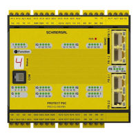
schmersal PSC1-E-37-14DI-4DO-2RO-RIO Installation Manual (201 pages)
Brand:
schmersal
| Category:
Control Unit
| Size: 4.81 MB
Table of Contents
Table of Contents
4
1 Important Notes
7
2 Definitions
7
Reference Documents
8
Abbreviations Used
9
3 Safety Instructions
10
Intended Use
10
Usage in Regions with UL/CSA Requirement
11
General Safety Instructions
12
Operating and Service
13
Transport/Storage
14
Module Overview
15
Device Characteristic Data
16
Basic Modules
16
PSC1-C-100 (-Fbx (1) ) (-MC)
16
Central Expansion Modules
20
Expansion Module PSC1-E-21-SDM1
20
Expansion Module PSC1-E-22-SDM1-2
22
Expansion Module PSC1-E-23-SDM2
24
Expansion Module PSC1-E-24-SDM2-2
26
Expansion Modules PSC1-E-131 and PSC1-E-133
28
Decentral Expansion Module
31
Psc1-E-37
33
Optional Universal Communication Interface
34
Tech. Characteristic Data: Optional Universal Communication Interface
35
Using the Memory Card
36
Encoder Specifications
37
Derating Outputs
37
Marking
38
Type Plate
38
Items Supplied
39
4 Safety-Related Features
40
General Layout, Safety-Related Architecture and Characteristic Data
40
Safety-Related Characteristic Data and Circuitry for Sensors Connected
44
Digital Sensors
44
Characteristics of the Sensors / Input Elements
44
DC Digital Sensors/Inputs
45
Classification of the Safe Digital Inputs
49
Connection Examples, Digital Sensors/Safety Switch
51
Overview of Achievable PL for Digital Safety Inputs
56
Sensors for Speed And/Or Position Acquisition
58
General Safety-Related Layout of Sensor Interface for Position And/Or Speed
58
General Diagnostic Measures for Encoder Interface
59
Encoder Types and Their Combinations, Diagnostic Characteristic Data
60
Specific Diagnostic Measures in Relation to the Encoder Type Used
66
Safety-Related Shutdown Thresholds, Encoder Systems for Position and Speed Acquisition
67
Safety-Related Assessment of the Encoder Types and Their Combination
70
Safety-Related Characteristic Data and Circuitry for the Outputs
72
Characteristics of the Output Elements
72
Diagnostics in the Shutdown Circuit
74
Diagnostic Functions
74
Overview of DC in Relation to Selected Diagnostic Functions
75
Permissible Capacitive and Inductive Load on Safe Outputs
76
Digital Outputs
77
Example Circuits, Basic Outputs
79
Digital Outputs I/O (Iqqx)
86
Classification of the I/O (Iqqx) When Used as an Output
86
Example Circuits for Safe Digital Outputs I/O (Iqqx)
87
Overview of Achievable PL for Digital Safety Outputs
93
5 Connection and Installation
95
General Installation Instructions
95
Installation and Mounting PSC1 Module
96
Mounting Backplane Bus
96
Arrangement Examples
97
PSC1-C-100-Fbx + PSC1-E-23-SDM2
97
Psc1-C-100 + Psc1-E-24-Sdm2-2
97
Mounting the Modules
98
Mounting on C Rail
98
Mounting on Backplane Bus
99
Installation and Configuration of Master Master (SMMC) and Master Slave (SDDC)
100
Schematic Diagram of the Network Topology
101
Installation of I/O Expansion
102
Physical Address Configuration for the Slave Modules (Central/Decentral)
102
Terminal Assignment
103
Terminal Assignment PSC1-C-100 (-Fbx/-MC)
104
Terminal Assignment PSC1-E-21-SDM1
106
Terminal Assignment PSC1-E-22-SDM1-2
107
Terminal Assignment PSC1-E-23-SDM2
109
Terminal Assignment PSC1-E-24-SDM2-2
111
Terminal Assignment PSC1-E-131
114
Terminal Assignment PSC1-E-133
115
Terminal Assignment PSC1-E-37
118
Terminal Assignment PSC1-C-100-Fbx
119
External 24 VDC Power Supply
120
Connection of the External Encoder Supply
122
Incremental, HTL, SIN/COS, SSI
122
Resolver
124
Connection of the Digital Inputs
125
Connection of Position and Speed Sensors
126
General Instructions
126
Pin Assignment on the Encoder Interface
128
Connection Variants
129
Connection of an Absolute Encoder as Master
129
Connection of an Absolute Encoder as Slave
130
Connection of an Incremental Encoder with TTL Signal Level
131
Connection of a SIN/COS Encoder
132
Connection of Resolver as Master
133
Connection of Resolver as Slave
134
Connection of Proximity Switches
135
Connection of Htl/Proximity Switches
136
Configuration of the Measurement Sections
138
General Description of the Encoder Configuration
138
Sensor Type
138
Absolute Encoder
138
Incremental Encoder
140
Sinecosine Encoder - Standard Mode
140
Sinecosine Encoder - High-Resolution Mode
140
Proximity Switch
141
Extended Monitoring with 2 Proximity Switches
142
HTL Sensor
143
Resolver
143
6 Response Times of the Psc1
145
Response Times in Standard Operation
146
Response Times for FAST_CHANNEL
147
Response Times for Overspeed Distance Monitoring
147
Response Times When Using the Inputs and Outputs on the Expansion Modules
149
7 Commissioning
151
Procedure
151
Sequences for Switching on
151
Reset Behaviour
153
Reset Types and Triggering Element
154
Reset Timing
155
Reset Function
155
Example Reset Function with Protection against Incorrect Usage
157
LED Indication
160
Parameter Configuration
161
Function Check
161
Validation
161
8 Safety-Related Check
162
9 Maintenance
163
Modification / Dealing with Changes to the Device
163
Replacement of a Module
163
Servicing Interval
163
10 Technical Specifications
164
Ambient Conditions
164
Safety-Related Characteristic Data
164
11 Switch Types
165
12 Notes for Designing, Programming, Validating and Testing Safety-Related Applications
171
Risk Assessment
171
Technical Documentation Required
173
Steps Required for Designing, Realisation and Testing
174
Phases of the V Model
175
Specification of the Safety Requirements (Breakdown)
176
Specification of the Functional Safety System
179
Definition of the Safety Functions
179
Performance Level Required (Plr) (Additional Emergency Stop)
180
Example - Specification of the Safety Functions in Tabular Form
181
Software Specification
182
Hardware Specification
184
Selection of SRP/CS and Equipment
184
Examples for Hardware Specification
185
Consideration of Systematic Failures
186
Hardware and Software Design
188
Check of the Hardware Design
188
Iterative Check on the Safety Level Achieved
188
Verification of Software (Program) and Parameters
191
FUP Check
191
Validating FUP against IL and Parameters Using Validation Report
193
Performance of System Tests / FIT Test (Fault Injection Test)
195
13 Appendix
196
Appendix A - Categorisation of the Switch Types
196
CE - Declaration of Conformity
201
Advertisement
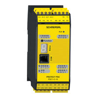
schmersal PSC1-E-37-14DI-4DO-2RO-RIO Installation Manual (189 pages)
Brand:
schmersal
| Category:
Control Unit
| Size: 9.01 MB
Table of Contents
Table of Contents
4
Important Notes
8
Definitions
8
Reference Documents
9
Abbreviations Used
10
Safety Instructions
11
Intended Use
11
Usage in Regions with UL/CSA Requirement
12
General Safety Instructions
13
Operating and Service
14
Transport/Storage
15
Module Overview
16
Device Characteristic Data
17
Basic Modules
17
PSC1-C-10 (-Fbx
17
Tech. Characteristic Data PSC1-C-10 (-Fbx /MC)
19
PSC1-C-10-SDM1 (-Fbx /MC)
21
Tech. Characteristic Data PSC1-C-10-SDM1 (-Fbx /MC)
23
PSC1-C-10-SDM2 (-Fbx /MC)
27
Tech. Characteristic Data PSC1-C-10-SDM2 (-Fbx (1) )
27
Central Expansion Modules
29
PSC1-E-31 and PSC1-E-33
29
Tech. Characteristic Data: PSC1-E-31 and PSC1-E-33
31
Decentralised Expansion Modules (in Preparation)
33
Psc1-E-37
33
Tech. Characteristic Data: PSC1-E-37
34
Optional Universal Communication Interface
36
Tech. Characteristic Data: Optional Universal Communication Interface
37
Possible Combinations
38
Using the Memory Card
38
Encoder Specifications
39
Derating Outputs
39
Marking
40
Type Plate
40
Items Supplied
41
Safety-Related Features
42
General Layout, Safety-Related Architecture and Characteristic Data
42
Safety-Related Characteristic Data and Circuitry for Sensors Connected
44
Digital Sensors
44
Characteristics of the Sensors / Input Elements
44
DC Digital Sensors/Inputs
45
Classification of the Safe Digital Inputs
49
Connection Examples, Digital Sensors/Safety Switch
51
Overview of Achievable PL for Digital Safety Inputs
56
Sensors for Speed And/Or Position Acquisition
58
General Safety-Related Layout of Sensor Interface for Position And/Or Speed
58
General Diagnostic Measures for Encoder Interface
59
Encoder Types and Their Combinations, Diagnostic Characteristic Data
60
Specific Diagnostic Measures in Relation to the Encoder Type Used
66
Safety-Related Shutdown Thresholds, Encoder Systems for Position and Speed Acquisition
67
Safety-Related Assessment of the Encoder Types and Their Combination
71
Safety-Related Characteristic Data and Circuitry for the Outputs
73
Characteristics of the Output Elements
73
Diagnostics in the Shutdown Circuit
75
Diagnostic Functions
75
Overview of DC in Relation to Selected Diagnostic Functions
76
Permissible Capacitive and Inductive Load on Safe Outputs
77
Digital Outputs
78
Example Circuits, Basic Outputs
80
Digital Outputs I/O (Iqqx)
87
Classification of the I/O (Iqqx) on Usage as an Output
87
Example Circuits for Safe Digital Outputs I/O (Iqqx)
88
Overview of Achievable PL for Digital Safety Outputs
94
Connection and Installation
96
General Installation Instructions
96
Installation and Mounting PSC1 Module
97
Mounting Backplane Bus
97
Arrangement Examples
98
Psc1-C-10-Sdm1 + Psc1-E-31
98
Psc1-C-10-Sdm2 + Psc1-E-33
98
Mounting the Modules
99
Mounting on C Rail
99
Mounting on Backplane Bus
100
Installation and Configuration of Master Master (SMMC) and Master Slave (SDDC)
101
Schematic Diagram of the Network Topology
102
Installation of I/O Expansion
103
Physical Address Configuration for the Slave Modules (Central / Decentral)
103
Terminal Assignment
104
Terminal Assignment PSC1-C-10 (-Fbx/-MC)
105
Terminal Assignment PSC1-C-10-SDM1 (-Fbx/-MC)
107
Terminal Assignment PSC1-C-10-SDM2 (-Fbx/-MC)
109
Terminal Assignment PSC1-E-31
111
Terminal Assignment PSC1-E-33
112
Terminal Assignment PSC1-E-37 in Preparation
114
Terminal Assignment PSC1-C-10(-Sdmx)-Fbx
115
External 24 VDC Power Supply
116
Connection of the External Encoder Supply
118
Incremental, HTL (on Request), SIN/COS, SSI
118
Connection of the Digital Inputs
120
Connection of Position and Speed Sensors
121
General Instructions
121
Encoder Interface Assignment
123
Connection Variants
124
Connection of an Absolute Encoder as Master
124
Connection of an Absolute Encoder as Slave
125
Connection of an Incremental Encoder with TTL Signal Level
126
Connection of a SIN/COS Encoder
127
Connection of Proximity Switch PSC1-C-10-SDM1/2
128
Configuration of the Measurement Sections
129
General Description of the Encoder Configuration
129
Sensor Type
129
Absolute Encoder
129
Incremental Encoder
131
Sinecosine Encoder - Standard Mode
131
Proximity Switches
131
Extended Monitoring with 2 Proximity Switches
132
Response Times of the Psc1
133
Response Times in Standard Operation
134
Response Times for FAST_CHANNEL
135
Response Times for Overspeed Distance Monitoring
135
Response Times When Using the PSC1-E-3X
137
Commissioning
139
Procedure
139
Sequences for Switching on
139
Reset Behaviour
140
Reset Types and Triggering Element
141
Reset Timing
142
Reset Function
142
Example Reset Function with Protection against Incorrect Usage
144
LED Indication
147
Parameter Configuration
148
Function Test
148
Validation
148
Safety-Related Check
149
Maintenance
150
Modification / Dealing with Changes to the Device
150
Replacement of a Module
150
Servicing Interval
150
Technical Data
151
Ambient Conditions
151
Safety-Related Characteristic Data
151
Switch Types
152
Notes for Designing, Programming, Validating and Testing Safety-Related Applications
158
Risk Assessment
158
Technical Documentation Required
160
Steps Required for Designing, Realisation and Testing
161
Phases of the V Model
162
Specification of the Safety Requirements (Breakdown)
163
Specification of the Functional Safety System
166
Definition of the Safety Functions
166
Performance Level Required (Plr) (Additional Emergency Stop)
166
Example - Specification of the Safety Functions in Tabular Form
167
Software Specification
168
Hardware Specification
170
Selection of SRP/CS and Equipment
170
Examples for Hardware Specification
171
Consideration of Systematic Failures
172
Hardware and Software Design
174
Check on the Hardware Design
174
Iterative Check on the Safety Level Achieved
174
Verification of Software (Program) and Parameters
178
FUP Check
178
Validating FUP against IL and Parameters Using Validation Report
181
Performance of System Tests / FIT Test (Fault Injection Test)
183
schmersal PSC1-E-37-14DI-4DO-2RO-RIO Installation Manual (173 pages)
Brand:
schmersal
| Category:
Control Unit
| Size: 3.02 MB
Table of Contents
Table of Contents
4
Important Notes
7
Definitions
7
Reference Documents
8
Abbreviations Used
9
Safety Instructions
11
Intended Use
11
Usage in Regions with UL/CSA Requirement
11
General Safety Instructions
12
Operating and Service
13
Transport/Storage
13
Device Types
14
Module Overview
15
Device Characteristic Data
16
Basic Modules
16
PSC1-C-10 (-Fbx (1) /-MC)
16
Tech. Characteristic Data PSC1-C-10 (-Fbx (1) /MC)
18
Psc1-C-10-Sdm1
20
Tech. Characteristic Data PSC1-C-10-SDM1 (-Fbx /MC)
22
Psc1-C-10-Sdm2
24
Tech. Characteristic Data PSC1-C-10-SDM2 (-Fbx )
26
Central Expansion Modules
28
PSC1-E-31 and PSC1-E-33
28
Optional Universal Communication Interface
31
Tech. Characteristic Data: Optional Universal Communication Interface
32
Possible Combinations
32
Encoder Specifications
33
Derating Outputs
33
Marking
34
Type Plate
34
Items Supplied
35
Safety-Related Features
36
General Layout, Safety-Related Architecture and Characteristic Data
36
Safety-Related Characteristic Data and Circuitry for Sensors Connected
38
Digital Sensors
38
Characteristics of the Sensors / Input Elements
38
DC Digital Sensors/Inputs
39
Classification of the Safe Digital Inputs
43
Connection Examples, Digital Sensors/Safety Switch
45
Overview of Achievable PL for Digital Safety Inputs
50
Sensors for Speed And/Or Position Acquisition
52
General Safety-Related Layout of Sensor Interface for Position And/Or Speed
52
General Diagnostic Measures for Encoder Interface
53
Encoder Types and Their Combinations, Diagnostic Characteristic Data
54
Specific Diagnostic Measures in Relation to the Encoder Type Used
56
Safety-Related Shutdown Thresholds, Encoder Systems for Position and Speed Acquisition
57
Safety-Related Assessment of the Encoder Types and Their Combination
60
Safety-Related Characteristic Data and Circuitry for the Outputs
62
Characteristics of the Output Elements
62
Diagnostics in the Shutdown Circuit
64
Diagnostic Functions
64
Overview of DC in Relation to Selected Diagnostic Functions
65
Permissible Capacitive and Inductive Load on Safe Outputs
66
Digital Outputs
67
Characteristic Data of the Basic Outputs
67
Example Circuits, Basic Outputs
69
Digital Outputs I/O (Iqqx)
76
Classification of the I/O (Iqqx) on Usage as an Output
76
Example Circuits for Safe Digital Outputs I/O (Iqqx)
77
Overview of Achievable PL for Digital Safety Outputs
82
Connection and Installation
84
General Installation Instructions
84
Installation and Mounting PSC1 Module
86
Mounting Backplane Bus
86
Arrangement Examples
87
Psc1-C-10-Sdm1 + Psc1-E-31
87
Psc1-C-10-Sdm2 + Psc1-E-33
87
Mounting the Modules
88
Mounting on C Rail
88
Mounting on Backplane Bus
89
Installation of I/O Expansion
90
Physical Address Configuration for the Slave Modules
90
Installation and Configuration of Master Master (SMMC) and Master Slave (SDDC)
91
SMMC/SDDC Topology Rules
92
Exemplary Schematic Diagram of a Network Topology
93
Terminal Assignment
94
Terminal Assignment PSC1-C-10 (-Fbx/-MC)
95
Terminal Assignment PSC1-C-10-SDM1 (-Fbx/-MC)
96
Terminal Assignment PSC1-C-10-SDM2 (-Fbx/-MC)
97
Terminal Assignment PSC1-E-31
100
Terminal Assignment PSC1-E-33
101
External 24 VDC Power Supply
103
Connection of the External Encoder Supply
105
Incremental, SIN/COS, SSI
105
Connection of the Digital Inputs
106
Connection of Position and Speed Sensors
107
General Instructions
107
Encoder Interface Assignment
109
Connection Variants
110
Connection of an Absolute Encoder as Master
110
Connection of an Absolute Encoder as Slave
111
Connection of an Incremental Encoder with TTL Signal Level
112
Connection of a SIN/COS Encoder
113
Connection of Proximity Switch (PSC1-C-10-SDM1/2 Only)
114
Configuration of the Measurement Sections
115
General Description of the Encoder Configuration
115
Sensor Type
115
Absolute Encoder
115
Incremental Encoder
117
Sincos Encoder - Standard Mode
117
Proximity Switches
117
Extended Monitoring with 2 Proximity Switches
118
Response Times of the Psc1
119
Response Times in Standard Operation
120
Response Times for FAST_CHANNEL
121
Response Times for Overspeed Distance Monitoring
122
Response Times When Using the PSC1-E-3X
124
Commissioning
126
Procedure
126
Sequences for Switching on
126
Reset Behaviour
127
Reset Types and Triggering Element
127
Reset Timing
128
Reset Function
128
Example Reset Function with Protection against Incorrect Usage
130
LED Indication
133
Installation Manual
133
Parameter Configuration
134
Using the Memory Card
134
Function Test
135
Validation
135
Safety-Related Check
136
Maintenance
137
Modification / Dealing with Changes to the Device
137
Replacement of a Module
137
Servicing Interval
137
Technical Data
138
Ambient Conditions
138
Safety-Related Characteristic Data
138
Switch Types
139
Notes for Designing, Programming, Validating and Testing Safety-Related Applications
146
Risk Assessment
146
Technical Documentation Required
148
Steps Required for Designing, Realisation and Testing
149
Phases of the V Model
150
Specification of the Safety Requirements (Breakdown)
151
Specification of the Functional Safety System
154
Definition of the Safety Functions
154
Performance Level Required (Plr) (Additional Emergency Stop)
154
Example - Specification of the Safety Functions in Tabular Form
155
Software Specification
156
Hardware Specification
158
Selection of SRP/CS and Equipment
158
Examples for Hardware Specification
159
Consideration of Systematic Failures
160
Hardware and Software Design
161
Check on the Hardware Design
161
Iterative Check on the Safety Level Achieved
162
Verification of Software (Program) and Parameters
164
FUP Check
164
Validating FUP against IL and Parameters Using Validation Report
166
Performance of System Tests / FIT Test (Fault Injection Test)
169
Appendix
170
Appendix A - Categorisation of the Switch Types
170
PSC1-C-10 Installation Manual V2.6
173
CE - Declaration of Conformity
173
Advertisement
Advertisement
Related Products
schmersal PSC1-E-37 Series
schmersal PSC1-E-3 Series
schmersal PSC1-E-31-12DI-10DIO
schmersal PSC1-E-33-12DI-6DIO-4RO
schmersal PSC1-E-2 Series
schmersal PSC1-E-13 Series
schmersal PSC1-E-21-SDM1
schmersal PSC1-E-22-SDM1-2
schmersal PSC1-E-23-SDM2
schmersal PSC1-E-24-SDM2-2
schmersal Categories
Switch
Industrial Equipment
Control Unit
Security Sensors
Safety Equipment
More schmersal Manuals
Login
Sign In
OR
Sign in with Facebook
Sign in with Google
Upload manual
Upload from disk
Upload from URL