Sign In
Upload
Manuals
Brands
Sakai Manuals
Construction Equipment
SV540 Series
Sakai SV540 Series Manuals
Manuals and User Guides for Sakai SV540 Series. We have
2
Sakai SV540 Series manuals available for free PDF download: Shop Manual, Operating & Maintenance Instructions
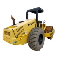
Sakai SV540 Series Shop Manual (306 pages)
Brand:
Sakai
| Category:
Construction Equipment
| Size: 45 MB
Table of Contents
Table of Contents
5
Safety
13
General Safety
15
Understanding the Safety Symbols and Words
15
General
15
Qualifications of Operators and Maintenance Personnel
16
Safety Practices and Policies
16
Pre Start Inspection
17
Safety Instructions
17
Operating
18
Starting
18
Stopping
18
Maintenance
19
Transporting the Machine
21
Specifications
23
Specification Data
26
Sv540D
26
Sv540T
28
Sv540Tf
30
Sv540Df
32
Sv640D
34
Sv640T
36
Engine
38
Table of Standard Values
38
Propulsion
38
Hydraulic System
38
Steering
39
Brakes
39
Capacities
39
Fuel and Lubricants Specification
40
Rating
40
Recommended Lubricants
40
Tightening Torque Chart
41
Engine and Controls
43
Engine
45
Engine Mount
45
Engine Exterior
47
Fuel System
49
Control System
50
Forward-Reverse Control
50
Pump Mount
51
Installation of Pump
52
Hydraulic Systems
53
System Circuit Diagram
56
Graphic Symbols for Hydraulic Circuits
56
Hydraulic Circuit Diagram
59
Propulsion Hydraulic System
61
Propulsion Hydraulic Piping
61
Propulsion Hydraulic Piping (Front) (1)
61
Propulsion Hydraulic Piping (Front) (2)
63
Propulsion Hydraulic Piping (Rear)
65
Hydraulic Component Specifications
68
Hydraulic Pump Assembly (Propulsion + Vibrator)
68
Propulsion Hydraulic Motor (Front)
70
Gear Box
71
Propulsion Hydraulic Motor (Rear)
72
Motor Speed Change Solenoid Valve (Front)
73
Vibrator Hydraulic System
75
Vibrator Hydraulic Piping
75
Hydraulic Component Specifications
77
Vibrator Hydraulic Motor
77
Steering System
79
Steering Hydraulic Piping
79
Steering Wheel
81
Hydraulic Component Specifications
82
Orbitrol
82
Steering • Charge Pump
83
Electrical System
85
PRECAUTIONS for Work
87
Wire Numbers, Wire Sizes, Wire Colors and Connectors Shown in Electrical Circuit Diagram, Wiring Harness Layout and Wiring Harnesses
87
Electrical Equipment Installation
88
System Circuit Diagram
89
Electrical Circuit Diagram
89
Electrical Components
91
Battery Layout
91
Wiring Harness Layout (1)
93
Wiring Harness Layout (2)
95
Engine Harness
95
Panel Harness (1)
95
Fuse • Relay Harness (1)
95
Panel Harness (2)
95
Fuse • Relay Harness (2)
95
Battery Relay Harness
106
Starter Switch Harness
109
Control Harness
110
Control Switch Harness
111
Motor Rotation Sensor Harness (Front)
112
Fuel Unit Harness
113
Diagnostic Switch Harness
114
Electrical Component Specifications
115
Fuse Box (1)
115
Fuse Box (2)
116
Combination Meter
117
Vibratory Drum • Rear Axle
119
Precautions for Disassembly and Reassembly
121
Vibratory Drum
123
Removal and Installation of Vibratory Drum
123
Removal of Vibratory Drum
123
Installation of Vibratory Drum
126
Vibratory Drum Assembly
127
Disassembly and Reassembly of Vibratory Drum
129
Disassembly of Vibratory Drum
129
Reassembly of Vibratory Drum
140
Rear Axle
159
Rear Axle (SV540/640D)
159
Rear Axle (SV540/640T, TF, DF)
161
Rear Axle Lubrication
163
Rear Axle Structure
164
Center Housing
164
Differential
165
Hub Reduction Gear
166
Brake
167
Gear Box
168
Brake
169
Brake Pedal
171
Brake Hydraulic Piping
173
Brake System
175
Hydraulic Component Specifications
176
Brake Solenoid Valve
176
Valve Block
177
Inspection and Adjustment
179
Safety Precautions for Inspection and Adjustment
181
Preparation for Inspection and Adjustment
181
Precautions for Inspection and Adjustment
181
Inspection and Adjustment of Engine Related Items
181
Warm-Up
181
Measurement
182
Measurement and Adjustment of Propulsion Circuit Pressure
182
Adjustment
183
Measurement and Adjustment of Propulsion Charge Circuit
184
Pressure
185
Measurement
185
Adjustment
186
MEASUREMENT of MACHINE High/Low SPEED CHANGE CIRCUIT PRESSURE
187
Measurement of Propulsion Motor (Front)
187
Measurement of Propulsion Motor (Rear)
188
Measurement
189
Measurement of Parking Brake Release Pressure
189
Measurement and Inspection of Vibrator Circuit Pressure
190
Measurement
190
Inspection
191
Measurement and Adjustment of Vibrator Charge Circuit
192
Pressure
193
Measurement
193
Adjustment
194
MEASUREMENT of VIBRATOR High/Low CHANGE CIRCUIT PRESSURE
195
Measurement
195
Measurement
196
Measurement and Inspection of Steering Circuit Pressure
196
Inspection
197
Measurement of Hydraulic Pump Case Pressure
198
Measurement of Propulsion Pump Case Pressure
198
Measurement of Vibrator Pump Case Pressure
199
Measurement of Propulsion Motor Case Pressure
200
Measurement of Propulsion Motor (Front)
200
Measurement of Propulsion Motor (Rear)
201
Measurement of Vibrator Motor Case Pressure
202
Measurement
202
Adjustment
203
Adjustment of F-R Lever Linkage
203
Brake Adjustment
204
Manually Releasing the Brake
204
Adjustment after Manual Release of Brake
205
Troubleshooting
207
Safety Precautions for Troubleshooting
209
Important Information for Troubleshooting
209
Before Starting
210
Wire Number and Color Code
210
Electrical System Troubleshooting
211
Precautions to Take During Electrical Circuit Fault Diagnosis
211
When Performing Electrical System Fault Diagnosis
211
Inspection Procedures Using a Tester
212
Inspection of Electrical System
217
Fault Codes
219
Fault Detection
219
Fault Lamps
219
Flash out of Fault Codes
220
Fault Code List
221
Error Codes
230
Engine
233
Engine will Not Start (Starter Motor Does Not Run) 1/4
233
Engine will Not Start (Starter Motor Does Not Run) 2/4
235
Engine will Not Start (Starter Motor Does Not Run) 3/4
237
Engine will Not Start (Starter Motor Does Not Run) 4/4
239
Engine will Not Start (but Starter Motor Runs)
241
No Charging
243
Grid Heater Does Not Work
243
Engine Speed Cannot be Switched
245
Propulsion
247
Machine Moves Neither Forward nor Backward
247
Machine Speed Cannot be Changed 1/5
249
Machine Speed Cannot be Changed 2/5
251
Machine Speed Cannot be Changed 3/5
253
Machine Speed Cannot be Changed 4/5
255
Machine Speed Cannot be Changed 5/5
257
Brake Cannot be Released
259
Brake Does Not Work
261
Vibration
263
No Vibration Occurs 1/3
263
No Vibration Occurs 2/3
265
No Vibration Occurs 3/3
267
Amplitude Does Not Change (Remains Either Low or High) 1/3
269
Amplitude Does Not Change (Remains Either Low or High) 2/3
271
Amplitude Does Not Change (Remains Either Low or High) 3/3
273
Vibration Mode Cannot be Switched
275
Vibrator Force Is Low in ECO Mode
277
Lighting
279
Combination Meter Warning Lamp or Indicator Lamp Is Abnormal
279
Tachometer Reading Is Abnormal
281
Hour Meter Is Abnormal
281
Temperature Meter Is Abnormal
283
Fuel Meter Is Abnormal
283
Hydraulic Oil Filter Warning Lamp Remains on
285
Engine Oil Pressure Warning Lamp Remains on
287
Vibration Indicator Lamp Does Not Light
289
Parking Brake Indicator Lamp Does Not Light
291
ECO Mode Indicator Lamp Does Not Light
293
Horn Does Not Sound
295
Backup Buzzer Does Not Sound
295
Hydraulic System Troubleshooting
296
When Performing Hydraulic System Troubleshooting
296
Propulsion System
297
Machine Moves Neither Forward nor Backward 1/2
297
Machine Moves Neither Forward nor Backward 2/2
298
Machine Moves in One Direction Only (Forward or Backward)
298
Slow Machine Speed or Small Drive Force 1/2
298
Slow Machine Speed or Small Drive Force 2/2
299
Machine Speed Cannot be Switched
299
Machine Does Not Stop Completely with F-R Lever in "N
299
Propulsion System Is Overheating
300
Abnormal Noise from Propulsion System
300
Vibrator System
301
No Vibration
301
Vibrator Frequency Is too Low
302
Amplitude Does Not Switch between High and Low
302
Vibrator Does Not Stop
303
Vibrator System Is Overheating
303
Abnormal Noise from Vibrator System
303
Steering System
304
Steering Wheel Is Hard to Turn
304
Steering Response Is Slow
304
Steering Wheel Backlash or Play Is Large
305
Steering System Is Overheating
305
Abnormal Noise from Steering System
305
Advertisement
Sakai SV540 Series Operating & Maintenance Instructions (108 pages)
Brand:
Sakai
| Category:
Construction Equipment
| Size: 9 MB
Table of Contents
Table of Contents
3
Machine and Engine Identification Numbers
6
Safety Notices
7
1 Basic Safety Precautions
9
General Precautions
9
Preparation for Safe Operation
13
Before Starting the Engine
14
After Starting the Engine
16
During Operation
17
Loading and Unloading
21
Transportation
21
Handling the Battery
22
Towing
23
Before Servicing
24
During Servicing
26
Safety Decals
29
2 Operation
31
Instruments and Controls
31
Operator's Station
31
Gauges, Indicator Lamps and Warning Lamps
32
Switches
36
Operating Levers / Pedals
40
Unloader Valve
41
Fuse Box
42
Handling and Adjustments
43
Seat Adjustment
43
Scraper Adjustment and Replacement
44
Disengaging the Brake When Towing
45
Engine Troubleshooting
46
Operation
47
Before-Starting Inspection
47
Starting the Engine
48
After Starting the Engine
49
Traveling
50
Stopping / Parking
52
Stopping the Engine
53
Check after Stopping the Engine
53
Vibratory Operation
54
Precautions for Work
56
Compaction Operation
56
When Going Downhill
56
On a Slope
56
Applicable Jobs
57
After Operation
58
Loading and Unloading
58
Use of a Trailer Equipped with a Winch
59
Self-Propelling
59
After Loading the Machine
60
Transportation
60
Operation in Cold Weather
60
Fuel Oil and Grease
60
Coolant
61
Battery
62
When the Cold Season Is over
63
For a Long Storage Period
63
During the Storage Period
64
When the Battery Has Discharged
64
Connection and Disconnection of Booster Cables
65
3 Periodic Maintenance
67
Precautions
67
Lifting the Machine by Hoist
70
Walk-Around Checking
71
Tire Inflation Pressure Check
72
Checking for External Injury to a Tire
72
Periodic Maintenance Points
73
Maintenance Procedure
75
Every 10 Service Hours or Daily
75
Every 50 Service Hours
78
Every 250 Service Hours
80
Every 500 Service Hours
83
Every 1000 Service Hours
86
As Required
88
Consumable Parts
93
Fluid and Lubricant Capacities
95
Electric Wiring Diagram
97
4 Specifications
100
Advertisement
Related Products
Sakai SV505-1 Series
Sakai SV540D
Sakai SV540T
Sakai SV540DF
Sakai SV540TF
Sakai SV540TB
Sakai SV540FB
Sakai SV544
Sakai SV510-III
Sakai SV204D
Sakai Categories
Construction Equipment
Vibratory rammers & tampers
Power Roller
Power Tool
Garbage Disposal
More Sakai Manuals
Login
Sign In
OR
Sign in with Facebook
Sign in with Google
Upload manual
Upload from disk
Upload from URL