Sign In
Upload
Manuals
Brands
ROOTECH Manuals
Measuring Instruments
ACCURA 3500
ROOTECH ACCURA 3500 Manuals
Manuals and User Guides for ROOTECH ACCURA 3500. We have
3
ROOTECH ACCURA 3500 manuals available for free PDF download: User Manual, Quick Setup Manual
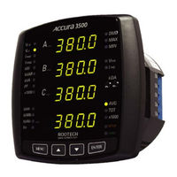
ROOTECH ACCURA 3500 User Manual (80 pages)
High Accuracy Digital Power Meter Added with Extension Modules.
Brand:
ROOTECH
| Category:
Measuring Instruments
| Size: 2 MB
Table of Contents
Table of Contents
9
Chapter 1 Introduction
14
Overview
14
Power Measurements, Digital/Analog Input and Output Integration
14
Accuracy, Power Quality
14
CE/UL Safety and Reliability
14
Easy Adding of Modules
14
Communication[Irda and RS485]
15
Fig 1.1 Accura Handheld PC Software
15
Features
16
Measurement
16
Power Quality
16
Basic Module
16
Extension Module[Only One Module to be Chosen as Option]
16
Communication
17
Irda Communication
17
Power Supply
17
Applications
18
True RMS Measurements Robust to Harmonics
18
Power Quality Analysis
18
Module Structure to Adapt to Different Requirements in the Field
18
Compatibility with Analog Meters
18
High Reliability Energy Management
18
Parameters
19
Chapter 2 Mounting
20
Environmental Conditions
20
Enclosure Considerations
20
Before You Begin
21
Meter Overview
21
Fig 2.1 Front Side
21
Fig 2.3 Basic Module[Dio Module] Rear Side
21
Meter Dimensions
22
Fig 2.4 Front View
22
Step 1: Mounting
23
Sequence
23
Fig 2.8 ANSI 4
23
Step 2: Voltage and Current Inputs
24
Voltage Input
24
Fig 2.10 Voltage and Current Connector
24
Current Input
25
Wiring Diagram Using External Pts
26
Fig 2.11 Single Phase 2 Wires, Wiring Mode = 1P2U
26
Fig 2.12 Three Phase 3 Wire Open Delta Using 2Cts, Wiring Mode = 3P3O
27
Fig 2.13 Three Phase 3 Wire Open Delta Using 3Cts, Wiring Mode = 3P3O
27
Fig 2.14 Three Phase 4 Wires Using 3 Pts and 3 Cts, Wiring Mode = 3P4U
28
Direct Diagram Using no Pts
29
Fig 2.15 Single Phase 2 Wire Direct , Wiring Mode = 1P2U
29
Fig 2.16 Single Phase 3 Wire Direct Using 2 Cts, Wiring Mode = 1P3U
30
Fig 2.17 Three Phase 3 Wire Open Delta Direct, Wiring Mode = 3P3O
30
Fig 2.18 Three Phase 3 Wire Open Delta Direct Using 3 Cts, Wiring Mode = 3P3O
31
Fig 2.19 Three Phase 4 Wire Direct Using 3 Cts, Wiring Mode = 3P4U
31
Step 3: Wire the RS485 Communication
32
Fig 2.20 Communication Wiring
32
Step 4: Wire the Power Supply and Ground Terminal
33
Power Supply
33
Ground Terminal
33
Fig 2.21 Wiring of Power Supply and Ground Terminal
33
Step 5: Add a Basic Module[Dio Module]
34
Fig 2.22 Adding of a Basic Module
34
Step 6: Wire a Basic Module
35
DIO Module
35
Fig 2.25 DC Relay Application
36
Fig 2.26 AC Relay Application
36
Step 7: Wire the Power Supply and Ground Terminal of a Basic Module
37
Power Supply
37
Ground Terminal
37
Fig 2.27 Wiring of Power Supply and Ground Terminal of a Basic Module
37
Step 8: Add a Extension Module
38
Fig 2.28 Adding of a Extension Module
38
Step 9: Wire a Extension Module
39
DI Module
39
Fig 2.29 DI Module
39
DO Module
40
Fig 2.31 DO Module
40
Fig 2.32 DC Relay Application
41
AI Module
42
Fig 2.34 AI Module
42
AO Module
43
Fig 2.36 AO Module
43
A4P2/A2P4 Module
44
Fig 2.38 A4P2 Module
44
Fig 2.40 A4P2/ A2P4 Module Analog Output
44
Step 10: Wire the Power Supply and Ground Terminal of a Exension Module
46
Power Supply
46
Ground Terminal
46
Fig 2.42 Wiring of Power Supply and Ground Terminal of a Extension Module
46
Step 11: Power up the Meter
47
Chapter 3 Meter Operation/Setup
48
Display Mode
49
Fig 3.1 Measurement Groups
49
Setup Mode
52
Reset Mode
54
System Mode
55
Reactive Calculation Method
57
Module Mode
59
Module Display Menu
59
Fig 2.24 Digital Input
59
Fig 2.30 Digital Input
59
Fig 2.37 Analog Output
59
Fig 2.41 Pulse Output
59
Fig 3.6 AI Module Channel Information
59
Fig 3.3 DIO Module Channel Information
60
Fig 3.5 DO Module Channel Information
60
Fig 3.7 AO Module Channel Information
60
Fig 3.8 A4P2 Module Channel Information
61
Fig 3.9 A2P4 Module Channel Information
61
Module Setup Menu
62
Fig 2.23 DIO Module
63
Fig 3.10 DIO Module Digital Output Channel 1 Setup
64
Fig 3.12 DO Module Digital Output Channel 1 Setup
64
Fig 3.13 DO Module Digital Output Channel 2 Setup
64
Fig 3.14 DO Module Digital Output Channel 3 Setup
64
Fig 3.15 DO Module Digital Output Channel 4 Setup
64
APPENDIX A Standard Specification
72
APPENDIX B Standard Compliance
73
APPENDIX C Test Report
74
Measuring Test
74
Reliability Test
75
Advertisement
ROOTECH ACCURA 3500 User Manual (76 pages)
High Accuracy Digital Power Meter
Brand:
ROOTECH
| Category:
Measuring Instruments
| Size: 3 MB
Table of Contents
Table of Contents
7
Chapter 1 Introduction
11
Overview
11
Power Measurements, Digital/Analog Input and Output Integration
11
Accuracy, Power Quality
11
Easy Adding of Modules
11
Features
12
Measurement
12
Power Quality
12
Basic Module
12
Extension Module[Only One Module to be Chosen as Option]
12
Communication
13
Power Supply
13
Applications
14
True RMS Measurements Robust to Harmonics
14
Power Quality Analysis
14
Module Structure to Adapt to Different Requirements in the Field
14
Compatibility with Analog Meters
14
High Reliability Energy Management
14
Parameters
15
Item
15
Chapter 2 Mounting
16
Environmental Conditions
16
Before You Begin
17
Meter Overview
17
Fig 1.1 Front Side
17
Fig 1.3 Basic Module[Dio Module] Rear Side
17
Meter Dimensions
18
Fig 1.4 Front View
18
Step 1: Mounting
19
Sequence
19
Fig 1.8 ANSI 4
19
Step 2: Voltage and Current Inputs
20
Voltage Input
20
Fig 1.10 Voltage and Current Connector
20
Current Input
21
Wiring Diagram Using External Pts
22
Direct Diagram Using no Pts
25
Step 3: Wire the RS485 Communication
28
Fig 1.20 Communication Wiring
28
Step 4: Wire the Power Supply and Ground Terminal
29
Power Supply
29
Ground Terminal
29
Fig 1.21 Wiring of Power Supply and Ground Terminal
29
Step 5: Add a Basic Module[Dio Module]
30
Step 6: Wire a Basic Module
31
DIO Module
31
Fig 1.25 DC Relay Application
33
Step 7: Wire the Power Supply and Ground Terminal of a Basic Module
34
Power Supply
34
Ground Terminal
34
Step 8: Add a Extension Module
35
Step 9: Wire an Extension Module
36
DI Module
36
Fig 1.29 DI Module
36
DO Module
37
Fig 1.30 Digital Input
37
Fig 1.31 DO Module
37
Fig 1.32 DC Relay Application
38
Fig 1.33 AC Relay Application
38
AI Module
39
Fig 1.34 AI Module
39
Fig 1.35 Analog Input
39
AO Module
40
Fig 1.36 AO Module
40
Fig 1.37 Analog Output
40
A4P2/A2P4 Module
41
Fig 1.38 A4P2 Module
41
Fig 1.40 A4P2/ A2P4 Module Analog Output
41
Step 10: Wire the Power Supply and Ground Terminal of a Expansion Module
43
Power Supply
43
Ground Terminal
44
Step 11: Power up the Meter
44
Chapter 3 Meter Operation/Setup
45
Display Mode
46
Fig 2.1 Measurement Groups
46
Setup Mode
49
Reset Mode
51
System Mode
52
Reactive Calculation Method
54
Module Mode
56
Module Display Menu
56
Fig 1.41 Pulse Output
56
Fig 2.6 AI Module Channel Information
56
Fig 2.3 DIO Module Channel Information
57
Fig 2.5 DO Module Channel Information
57
Fig 2.7 AO Module Channel Information
57
Fig 2.8 A4P2 Module Channel Information
58
Fig 2.9 A2P4 Module Channel Information
58
Module Setup Menu
59
Fig 1.23 DIO Module
62
Fig 2.12 DO Module Digital Output Channel 1 Setup
62
Fig 2.13 DO Module Digital Output Channel 2 Setup
62
Fig 2.14 DO Module Digital Output Channel 3 Setup
62
Fig 2.15 DO Module Digital Output Channel 4 Setup
62
APPENDIX A Standard Specification
71
APPENDIX B Standard Compliance
72
APPENDIX C Test Report
73
Measuring Test
73
Reliability Test
74
APPENDIX D Order Information
75
ROOTECH ACCURA 3500 Quick Setup Manual (12 pages)
High Accuracy Digital Power Meter
Brand:
ROOTECH
| Category:
Measuring Instruments
| Size: 2 MB
Table of Contents
Table of Contents
3
PT Ratio
4
Wiring Mode
6
Protocol
8
Parity Bits
10
Stop Bits
11
Advertisement
Advertisement
Related Products
ROOTECH ACCURA 3550
ROOTECH Accura 3550S
ROOTECH ACCURA 3500S
ROOTECH ACCURA 3300S
ROOTECH ACCURA 3300E
ROOTECH ACCURA 3700 Series
ROOTECH Accura 3700 DIO
ROOTECH Accura 3700 RTD
ROOTECH Accura 3700 ELD
ROOTECH Accura 3700 A2D4
ROOTECH Categories
Measuring Instruments
I/O Systems
Relays
Control Unit
Thermostat
More ROOTECH Manuals
Login
Sign In
OR
Sign in with Facebook
Sign in with Google
Upload manual
Upload from disk
Upload from URL