Sign In
Upload
Manuals
Brands
ROOTECH Manuals
Measuring Instruments
ACCURA 3500S
ROOTECH ACCURA 3500S Manuals
Manuals and User Guides for ROOTECH ACCURA 3500S. We have
2
ROOTECH ACCURA 3500S manuals available for free PDF download: User Manual
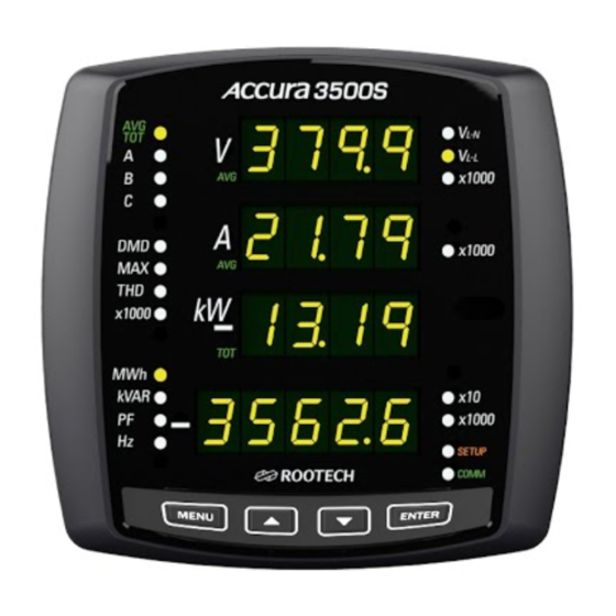
ROOTECH ACCURA 3500S User Manual (76 pages)
High Accuracy Digital Power Meter
Brand:
ROOTECH
| Category:
Measuring Instruments
| Size: 2 MB
Table of Contents
Notice
1
Table of Contents
8
Chapter 1 Introduction
13
Overview
13
Cost-Effective Power Meter Providing Digital/Analog Inputs and Outputs
13
Accurate Measurements/ Power Quality Data Available
13
CE/UL Safety and Reliability
13
Easily Attachable I/O Modules
14
Features
15
Measurement
15
Power Quality
15
Basic Module
15
Expansion Module
15
Communication
16
Power Supply
16
Applications
17
True RMS Measurements
17
Power Quality Analysis
17
Module Structure to Adapt to Different Requirements in the Field
17
Ideal for Replacing Analog Meters
17
Highly Reliable Energy Management
17
Parameters
19
Item
19
Chapter 2 Mounting
20
Environmental Conditions
20
Before You Begin
21
Meter Overview
21
Fig 1.1 Front Side
21
Fig 1.3 Rear Side of Basic Module[Dio Module]
21
Meter Dimensions
22
Fig 1.4 Front View
22
Step 1: Mounting
23
Sequence
23
Fig 1.8 ANSI 4
23
Step 2: Voltage and Current Inputs
24
Voltage Input
24
Fig 1.10 Voltage and Current Connector
24
Current Input
25
Wiring Diagram Using External Pts
26
Fig 1.11 Single Phase 2 Wire Connection, Wiring Mode = 1P2U
26
Fig 1.14 Three Phase 4 Wire Connection Using 3 Pts and 3 Cts, Wiring Mode = 3P4U
28
Direct Connection Diagram Using no Pts
29
Fig 1.15 Single Phase 2 Wire Direct Connection, Wiring Mode = 1P2U
29
Fig 1.16 Single Phase 3 Wire Direct Connection Using 2 Cts, Wiring Mode = 1P3U
30
Fig 1.17 Three Phase 3 Wire Open Delta Direct Connection, Wiring Mode = 3P3O
30
Fig 1.18 Three Phase 3 Wire Open Delta Direct Connection Using 3 Cts Wiring Mode = 3P3O
31
Fig 1.19 Three Phase 4 Wire Direct Connection Mode Using 3 Cts Wiring Mode = 3P4U
31
Step 3: Wiring the Device for RS485 Communication
32
Fig 1.20 Communication Wiring
32
Step 4: Wiring the Power Supply and Ground Terminal
33
Power Supply
33
Ground Terminal
33
Fig 1.21 Wiring of Power Supply and Ground Terminal
33
Step 5: Adding the Basic Module DIO Module]
34
Fig 1.22 Adding the Basic Module
34
Step 6: Wiring the Basic Module
35
DIO Module
35
Fig 1.24 Digital Inputs
36
Fig 1.25 DC Relay Application
37
Step 7: Wiring the Power Supply and Ground Terminal of the Basic Module
38
Power Supply
38
Fig 1.27 Wiring of Power Supply and Ground Terminal of the Basic Module
38
Ground Terminal
39
Step 8: Adding the Expansion Module
40
Fig 1.28 Adding the Expansion Module
40
Step 9: Wiring the Expansion Module
41
DI Module
41
Fig 1.29 DI Module
41
Fig 1.30 Digital Input
42
DO Module
43
Fig 1.31 DO Module
43
Fig 1.32 DC Relay Application
44
AI Module
45
Fig 1.34 AI Module
45
Fig 1.35 Analog Inputs
45
AO Module
46
Fig 1.36 AO Module
46
Fig 1.37 Analog Output
46
Step 10: Wiring the Power Supply and Ground Terminal of the Expansion Module
47
Power Supply
47
Fig 1.38 Wiring of Power Supply and Ground Terminal of the Expansion Module
47
Ground Terminal
48
Step 11: Powering up the Meter
49
Chapter 3 Meter Operation/Setup
50
Display Mode
51
Fig 2.1 Measurement Group A, B
51
Fig 2.2 Measurement Group C
51
Fig 2.3 Measurement Group D
51
Fig 2.4 X1000, X10 LED
52
Setup Mode
58
Reset Mode
60
System Mode
61
Reactive Power Calculation
63
Module Mode
66
Module Display Menu
66
Fig 2.6 DIO Module Channel Information
67
Fig 2.8 DO Module Channel Information
67
Fig 2.10 AO Module Channel Information
67
Module Setup Menu
68
Fig 2.11 DIO Module Digital Output Channel 1 Setup
71
Fig 2.12 DIO Module Digital Output Channel 2 Setup
71
Fig 2.13 DO † Module Digital Output Channel 1 Setup
71
Fig 2.14 DO † Module Digital Output Channel 2 Setup
71
Fig 2.15 DO † Module Digital Output Channel 3 Setup
71
Fig 2.16 DO † Module Digital Output Channel 4 Setup
71
Appendix A Specifications
72
Appendix B Standard Compliance
73
Appendix C Test Report
74
Measuring Test
74
Reliability Test
75
Advertisement
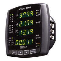
ROOTECH ACCURA 3500S User Manual (50 pages)
High Accuracy Digital Power Meter
Brand:
ROOTECH
| Category:
Measuring Instruments
| Size: 1 MB
Table of Contents
Electrical Symbols
3
Limitation of Liability
4
Warranty Information
5
Revision History
8
Table of Contents
9
Chapter 1 Introduction
12
Overview
12
Power Measurements
12
Accuracy
12
Power Quality
12
CE/UL Safety and Reliability
12
Features
13
Measurement
13
Power Quality
13
Communication
13
Power Supply
13
Applications
14
True RMS Measurements Robust to Harmonics
14
Power Quality Analysis
14
Compatibility with Analog Meters
14
High Reliability Energy Management
14
Parameters
15
Chapter 2 Mounting
16
Environmental Conditions
16
Enclosure Considerations
16
Before You Begin
17
Meter Overview
17
Fig 1.1 Front Side
17
Meter Dimensions
18
Fig 1.3 Front View
18
Fig 1.5 Side View
18
Step 1: Mounting
19
Sequence
19
Fig 1.6 ANSI 4
19
Step 2: Voltage and Current Inputs
20
Voltage Input
20
Fig 1.8 Voltage and Current Connector
20
Current Input
21
Wiring Diagram Using External Pts
22
Fig 1.9 Single Phase 2 Wires, Wiring Mode = 1P2U
22
Fig 1.10 Three Phase 3 Wire Open Delta Using 2Cts, Wiring Mode = 3P3O
23
Fig 1.11 Three Phase 3 Wire Open Delta Using 3Cts, Wiring Mode = 3P3O
23
Fig 1.12 Three Phase 4 Wires Using 3 Pts and 3 Cts, Wiring Mode = 3P4U
24
Direct Diagram Using no Pts
25
Fig 1.13 Single Phase 2 Wire Direct , Wiring Mode = 1P2U
25
Fig 1.14 Single Phase 3 Wire Direct Using 2 Cts, Wiring Mode = 1P3U
26
Fig 1.15 Three Phase 3 Wire Open Delta Direct, Wiring Mode = 3P3O
26
Fig 1.16 Three Phase 3 Wire Open Delta Direct Using 3 Cts, Wiring Mode = 3P3O
27
Fig 1.17 Three Phase 4 Wire Direct Using 3 Cts, Wiring Mode = 3P4U
27
Step 3: Wire the RS485 Communication
28
Fig 1.18 Communication Wiring
28
Step 4: Wire the Power Supply and Ground Terminal
29
Power Supply
29
Ground Terminal
29
Fig 1.19 Wiring of Power Supply and Ground Terminal
29
Step 5: Add a Cover/Power up the Meter
30
Add a Cover
30
Power up the Meter
30
Fig 1.20 Cover
30
Chapter 3 Meter Operation/Setup
31
Display Mode
32
Fig 2.1 Measurement Group A, B
32
Fig 2.2 Measurement Group C
32
Fig 2.3 Measurement Group D
32
Fig 2.4 X1000, X10 LED
33
Setup Mode
38
Reset Mode
40
System Mode
41
Reactive Calculation Method
43
APPENDIX A Standard Specification
45
APPENDIX B Standard Compliance
46
APPENDIX C Test Report
47
Measuring Test
47
Reliability Test
48
Index
49
Advertisement
Related Products
ROOTECH ACCURA 3500
ROOTECH ACCURA 3550
ROOTECH Accura 3550S
ROOTECH Accura 3700 AI
ROOTECH Accura 3700 AO
ROOTECH Accura 3700 DO
ROOTECH Accura 3700 A4D2
ROOTECH Accura 3700 DC
ROOTECH ACCURA 3000
ROOTECH Accura 3300
ROOTECH Categories
Measuring Instruments
I/O Systems
Relays
Control Unit
Control Systems
More ROOTECH Manuals
Login
Sign In
OR
Sign in with Facebook
Sign in with Google
Upload manual
Upload from disk
Upload from URL