Sign In
Upload
Manuals
Brands
Rohde & Schwarz Manuals
Measuring Instruments
NRT 1080.9506.02/.62
Rohde & Schwarz NRT 1080.9506.02/.62 Manuals
Manuals and User Guides for Rohde & Schwarz NRT 1080.9506.02/.62. We have
1
Rohde & Schwarz NRT 1080.9506.02/.62 manual available for free PDF download: Operating Manual
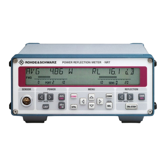
Rohde & Schwarz NRT 1080.9506.02/.62 Operating Manual (194 pages)
Power reflection meter
Brand:
Rohde & Schwarz
| Category:
Measuring Instruments
| Size: 1.71 MB
Table of Contents
Table of Contents
7
Preparation for Use
19
Front and Rear View (See Next Two Pages)
19
1.2 Putting into Operation
19
1.2.1 Unpacking
19
1.2.2 Setting up
19
Fig. 1-1 Front View - Display
20
Fig. 1-2 Rear View
21
1.2.3 Rackmounting
22
1.2.4 Connection to AC Supply
22
1.2.5 Power Fuses
23
1.2.6 Power up
23
1.2.7 Connecting a Sensor to the NRT
23
1.2.8 Switching Sensor into RF Circuit
24
1.2.9 EMC Shielding Measures
24
10Function/Power-Up Test
24
1.3 Installation of Options
25
Battery Operation (with Option NRT-B3)
26
1.4.1 General
26
1.4.2 Charging the Battery
26
1.4.3 Manual Start/Stop of Battery Charging
27
1.4.4 Reducing the Power Consumption
28
1.4.5 Preselection of on Period
29
1.4.6 Battery Counter
29
1.4.7 Replacing the Battery
30
Fig. 1-3 Replacing the Battery
30
Manual Operation
31
Short Introduction
31
Correct Connection of Sensor
31
Default Setup
31
Measuring the Power
32
Unit Selectable in W or Dbm
32
Measuring Relative Power Differences
32
Measuring Envelope Parameters (ENV)
33
Measuring the Reflection
34
Switching between SWR and Another Reflection Parameter
34
De)Activating the Acoustic Monitoring
34
Fixing the Display Range and Scaling
34
Enhanced Measurement Accuracy
35
Using Frequency Response Correction
35
Zeroing
37
Increasing the Measurement Accuracy for Modulated Signals
37
Selecting Forward Power (FWD) or Absorbed Power (F-R)
38
Reference Plane and Cable Losses
38
Measurement with Several Sensors
39
Basic Operating Functions
40
Front-Panel Keys
40
Fig. 2-1 Front-Panel Keys
40
Operation Via Function Keys
41
Scaling of Bargraphs and Underrange Identification
42
Selection of the Active Sensor
42
Menu Operation
43
Types of Menu Parameters
43
Numeric Entries
44
Menus and Notation
45
Config Menu
46
ENV KEY (Selection of Envelope Parameters)
47
Measurement of Peak Envelope Power
48
Crest Factor
49
Average Burst Power
50
Cumulative Distribution Function
52
POWER (Configuration of Power Display)
53
MAXHOLD (Min/Max Display On/Off)
53
MAXDISP (Display of Max Value, Min Value or Difference)
54
SCALE (Setting of Scale Limits for Bargraphs)
54
RESOL (Resolution of Indication in Display)
55
INT.TIME (Setting the Integration Time)
56
USER (Entry of a User-Defined Integration Time)
56
SPEC (Special Functions)
57
REF (Reference Value for Relative Power Measurements)
57
SWR.ALARM (SWR Monitoring)
57
KEY (Configuration of Relative Units)
58
Correction Menu
60
FREQ (Frequency Response Correction )
61
Entry of Carrier Frequency for NRT Sensors
61
Entry of Carrier Frequency for NAP Sensors
62
ZERO (Zeroing)
62
MODULATION (Correction of Measured Values with Modulated Signals)
63
MEAS.POS (Definition of Reference Plane)
64
DIRECTION (Selection of Forward Power Direction)
66
CALDATA (Entry of Calibration Factors)
67
Fig. 2-6 Correction Menu
67
Utility Menu
69
ILLUM (Switching off and on the Backlighting of the Display)
70
SETUP (Recalling and Storing Instrument Settings)
70
AUTO.OFF (Power-Saving Mode)
71
BATT.TIME (Battery Charging)
72
AFTER CHARGE (Automatic Switchoff after Charging)
72
BATTERY CHARGE (Manual Control of Battery Charging)
73
BEEPER (Alarm Message, Acknowledge Signal)
73
REMOTE (Remote-Control Settings)
74
AUX/IO (Configuration of IN/OUT Connector)
75
Configuration as a Monitoring Output: Selection of Bargraph
76
Entering the Monitoring Criteria
76
Selection of Output Level for SWR Alarm
77
Remote Control
81
Brief Instructions
81
IEC/IEEE-Bus
81
RS-232 Interface
82
Switchover to Remote Control
83
Remote Control Via IEC Bus
83
Setting the Device Address
83
Indications During Remote Control
83
Return to Manual Operation
84
Remote Control Via RS-232-Interface
84
Setting the Transmission Parameters
84
Indications During Remote Control
84
Return to Manual Operation
85
Messages
85
Interface Message
85
Device Messages (Commands and Device Responses)
85
Structure and Syntax of the Device Messages
86
SCPI Introduction
86
Structure of a Command
86
Fig. 3-1 Example for the Tree Structure of the SCPI Command Systems: the Sense System
87
Structure of a Command Line
89
Responses to Queries
89
Parameters
90
Overview of Syntax Elements
92
Description of Commands
93
Notation
93
Trigger and Measurement During Remote Control
95
Selection of Measurement Channel
97
Common Commands
98
Table 3-1 Common Commands
98
Table 3-2 Device Response to *OPT
99
Measurement Instructions
100
Calculate Subsystem
101
Table 3-5 Calibration System
102
Calibration Subsystem
103
Control Subsystem
104
Table 3-6 Control Subsystem
104
Diagnostic Subsystem
105
Table 3-7 Diagnostic Subsystem
105
10Input Subsystem
106
Table 3-8 Input Subsystem
106
11Sense Subsystem
108
Table 3-11 System Subsystem
120
Table 3-12 TEST Subsystem
122
Table 3-13 Trigger Subsystem
124
Table 3-14 UNIT Subsystem
125
Instrument Model and Command Processing
127
Input Unit
127
Fig. 3-2 Instrument Model in the Case of Remote Control by Means of the IEC Bus
127
Command Recognition
128
Data Set and Instrument Hardware
128
Status Reporting System
128
Output Unit
129
Command Sequence and Command Synchronization
129
Table 3-15 Synchronization with *OPC, *OPC? and *WAI
129
Status Reporting System
130
Structure of an SCPI Status Register
130
Fig. 3-3 the Status Register Model
130
Overview of the Status Registers
132
Fig. 3-4 the Status Registers
132
Description of the Status Registers
133
Status Byte (STB) and Service Request Enable Register (SRE)
133
Table 3-16 Meaning of the Bits Used in the Status Byte
133
IST Flag and Parallel Poll Enable Register (PPE)
134
Event Status Register (ESR) and Event Status Enable Register (ESE)
134
Table 3-17 Meaning of the Bits Used in the Event Status Register
134
Status:operation Register
135
Status:questionable Register
135
Table 3-18 Meaning of the Bits Used in the Status:operation Register
135
Table 3-19 Meaning of the Bits Used in the Status:questionable Register
135
Application of the Status Reporting Systems
136
Service Request, Making Use of the Hierarchy Structure
136
Serial Poll
137
Parallel Poll
137
Query by Means of Commands
137
Error Queue Query
137
Reset Values of the Status Reporting Systems
138
Maintenance and Troubleshooting
139
Maintenance
139
Cleaning the Outside
139
Replacing the Battery (Option NRT-B3)
139
Storage
140
Firmware Update
141
Loading New Firmware into Basic Unit
141
4.3 Functional Test
146
Troubleshooting
146
Detection of Faulty Module
146
Installation and Removal of Modules
148
Opening the Instrument
148
Fig. 4-3 Removing the Top and Bottom Cover
148
Option NRT-B1
149
Option NRT-B2
149
Option NRT-B3
150
Power Supply
151
Display Board
152
Mainboard
152
Checking the Rated Specifications
153
Measuring Equipment and Accessories
153
Test Setup for Checking the Option NRT-B1
154
Test Procedure
154
Switch-On Sequence
154
Display and Keypad
154
Display Test
154
Keypad Test
155
Acoustic Signal Device
155
Memory Test
155
Remote Control
155
IEC/IEEE BUS (IEC625 / IEEE488 Interface)
155
RS232 Interface
156
Sensor Interface
156
AUX Interface
156
Option NRT-B1
157
Sensor Identification
157
Zeroing
157
Power Measurement
158
Option NRT-B2
158
Option NRT-B3
158
Switchover AC Supply/Battery Operation
158
Battery Identification
159
Automatic Switch-Off of Charging
159
Test Report
160
Table 5-2 Test Report
160
Annex a Interfaces
161
Fig. A-1 Pin Assigment of the IEC-Bus Interface
161
Annex A.1.3 Interface Functions
162
Table A-1 Interface Functions
162
Annex A.1.4 Interface Messages
163
Table A-2 Universal Commands
163
Table A-3 Addressed Commands
163
Annex A.2 RS-232-C Interface
164
Annex A.2.1 Interface Characteristics
164
Annex A.2.2 Signal Lines
164
Fig. A-2 Pin Assigment of the RS-232-C Interface
164
Fig. A-3 Null Modem Connection Scheme
166
Annex B List of Error Messages
167
Annex B.1 SCPI-Specific Error Messages
167
Annex B.2 NRT-Specific Error Messages
174
Annex C
175
List of Commands
175
Annex D
179
Programming Examples
179
Annex D.1 Including IEC-Bus Library for Quickbasic
179
Annex D.2 Initialization and Default Status
179
Annex D.2.1 Initialize Controller
179
Annex D.2.2 Functions for Receiving and Sending Data and Commands
179
Annex D.2.3 Initialize the Instrument
180
Annex D.3 Sending Device Setting Commands
180
Annex D.4 Switchover to Manual Control
180
Annex D.5 Reading out Device Settings
181
Annex D.6 Performing a Measurement
181
Annex D.7 Command Synchronization
182
Annex D.8 Service Request
183
Annex E Default Settings
185
Table E-1 Default Settings
185
Advertisement
Advertisement
Related Products
Rohde & Schwarz NRT2
Rohde & Schwarz NRT2-B8
Rohde & Schwarz NRP2
Rohde & Schwarz NRX
Rohde & Schwarz NRX-B4
Rohde & Schwarz NRX-B8
Rohde & Schwarz NRX-K2
Rohde & Schwarz NRX-K4
Rohde & Schwarz NRP-Z00
Rohde & Schwarz NRPM OTA Power Measurement Solution
Rohde & Schwarz Categories
Measuring Instruments
Test Equipment
Power Supply
Portable Generator
Accessories
More Rohde & Schwarz Manuals
Login
Sign In
OR
Sign in with Facebook
Sign in with Google
Upload manual
Upload from disk
Upload from URL