Sign In
Upload
Manuals
Brands
Rockwell Automation Manuals
DC Drives
Allen-Bradley PowerFlex 6000
Rockwell Automation Allen-Bradley PowerFlex 6000 Manuals
Manuals and User Guides for Rockwell Automation Allen-Bradley PowerFlex 6000. We have
3
Rockwell Automation Allen-Bradley PowerFlex 6000 manuals available for free PDF download: User Manual, Commissioning Manual, Instructions Manual
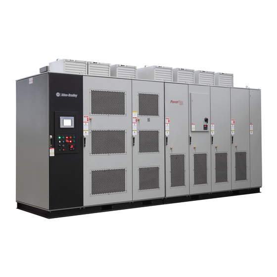
Rockwell Automation Allen-Bradley PowerFlex 6000 User Manual (154 pages)
Medium Voltage Variable Frequency Drive
Brand:
Rockwell Automation
| Category:
DC Drives
| Size: 15.81 MB
Table of Contents
Table of Contents
3
Preface
7
About this Publication
7
Who Should Use this Manual
7
What Is Not in this Manual
7
Download Firmware, AOP, EDS, and Other Files
7
Summary of Changes
8
General Precautions
8
Service and Support
8
Commissioning Support
8
Additional Resources
9
Introduction
11
Safety Considerations
11
Environmental Conditions
12
How It Works
12
Cascaded "H" Bridge (CHB) Topology
12
Simplified Electrical Diagrams
13
Standards Compliance
18
Drive System Layout
19
Elevation Drawings
19
Isolation Transformer Cabinet
20
Isolation Transformer
23
Isolation Transformer Temperature Monitor
24
Top-Mounted Cooling Fans
25
Incoming Line Power Cable Connections
25
Outgoing Motor Cable Connections
26
Door Position Limit Switch
26
Interlocking
27
Voltage Sensing Board
29
Power Module Cabinet
30
Power Modules
30
Hall Effect Current Sensors (Hecs)
34
Top-Mounted Cooling Fans
34
LV Control Cabinet
34
Control Unit (All Modules)
35
Plc
38
Hmi
38
Ups
38
Synchronous Transfer
39
Operator Interface
39
Basic Configurations
40
Setup and Operation
41
Main Interface
41
Drive Setup and Configuration Controls
41
Status Indicators
42
Operation Bar
43
Setup and Monitor Box
43
Main Interface Controls
43
Set Frequency (Hz)
44
Drive Operation Controls
45
View Version Information
46
Alarm
47
Alarm History
48
Trends
49
View Voltage, Current, or Frequency Trends
52
Customize a Trend
53
Operation
55
Confirm Bypass Mode
56
Choose Local/Remote Operation
57
Open/Close Drive Input and Output Contactors
58
Open/Close Bypass Contactors
59
Settings
60
System Settings
60
User Parameter Settings
61
Change User Parameters
62
Parameters and Function Codes
65
P Parameters
66
Preventative Maintenance and Component Replacement
83
Safety
83
Introduction
84
Daily Inspection
84
Clean the Air Filters
84
Regular Maintenance Intervals
84
Physical Checks (no Medium Voltage or Control Power)
85
Power Connection Inspection
85
Physical Inspection
85
Medium Voltage Testing
86
Maintenance after a Fault Condition
86
Isolation Transformer Cabinet
87
Replace/Clean Door-Mounted Air Filters
87
Inspect Top Mounted Cooling Fans
89
Replace Top Mounted Cooling Fans
90
Fan Balance
94
Inspect Isolation Transformer
94
Inspect Voltage Sensing Board
94
Replace Voltage Sensing Board
94
Inspect Door Position Limit Switch
97
Replace Door Position Limit Switch
97
Power Module Cabinet
98
Inspect, Clean, or Replace Door Mounted Air Filters
98
Inspect or Replace Top Mounted Cooling Fans
98
Inspect Power Modules
98
Replace Power Module
98
Replace Power Module Fuses
104
Inspect or Replace HECS
104
Inspect or Replace Door Position Limit Switch
107
LV Control Cabinet
108
Inspect AC/DC Power Supplies
108
Replace AC/DC Power Supplies
109
Inspect UPS
111
Replace UPS
112
Inspect PLC
114
Inspect/Replace Control Unit or Control Boards
114
Inspect the HMI
117
Replace the HMI
117
Replace LV Control Relays
118
Replace LV Control Circuit Breakers
120
Inspect Coils
121
Inspect Contacts
121
Inspect Pilot Lights
121
Inspect Locking and Interlocking Devices
122
Connections
122
Inspect LV Component Terminal and Plug-In Connections
122
Inspect Medium Voltage Cable Connections
122
Inspect Power Cable and Control Wire Terminals
122
Inspect Transformer Secondary Windings
122
Inspect Power Module Input and Output Power Connections
123
General
123
Review Firmware and Hardware
123
Inspect/Review Spare Parts
123
Professional Maintenance Service
123
Miscellaneous Preventive Maintenance Work
123
Tools/Materials/Documentation Requirements
124
Final Report
125
Prepare Final Report
125
Technical Specifications
127
Catalog Number Explanation
129
Powerflex 6000 Medium Voltage Variable Frequency Drives
129
Preventative Maintenance Schedule
131
Powerflex 6000 Maintenance Schedule
131
Spare Parts Storage
137
Requirements and Recommendations
137
Power Supplies
137
Power Cells
137
Signal Conditioners
137
Control Equipment and Boards
138
EC Cooling Fans
138
Spare Parts Maintenance Schedule
138
Spare Parts Connection Matrix
139
Power Supply Connection Guidelines
139
1606 Power Supply
139
Control Equipment and Boards Connection Guidelines
140
Control Unit
140
Power Components Connection Guidelines
142
Power Cells
142
Cooling System Connection Guidelines
144
EC Cooling Fans
144
Connection Wire Sizes
145
Guidelines for Extended Shutdown or Storage
146
Medium Voltage Supply
146
Storage Environment
146
Cooling Fans
146
Control Circuits
146
Power Cells
146
Guidelines for Inspection after Extended Shutdown or Storage
147
Visual Inspection
147
Cooling Fans
147
Control Circuits
147
Advertisement
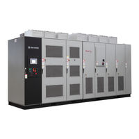
Rockwell Automation Allen-Bradley PowerFlex 6000 Commissioning Manual (128 pages)
Medium Voltage Variable Frequency Drive
Brand:
Rockwell Automation
| Category:
DC Drives
| Size: 10.1 MB
Table of Contents
Table of Contents
3
Introduction
7
Preface
7
Required Supplemental Information
7
Dimensional Drawings and Electrical Drawings
7
Shipping, Handling, and Installation Manual
8
What Is Not in this Manual
7
Who Should Use this Manual
7
Additional Resources
9
General Precautions
9
Chapter 1
11
Introduction
11
Overview
11
Documentation and Application Review
12
Review All Rockwell Automation Supplied Documentation
12
Pre-Commissioning Customer Meeting
13
Review Drive Application
13
Chapter 2
15
Gather Required Tools and Test Equipment
15
Lockout and Tagout
15
Preparation and Inspection (for IEC)
15
Inspect Drive Components
16
Functional Assessment
17
Interconnection Review
20
Installation Review
21
Mechanical Installation Inspection
21
Electrical Installation Inspection
22
Power Cabling
22
Control Wiring
23
Drive Megger Check
23
Isolate the Power and Control Circuits
23
Connect the Insulation Meter
27
Final Steps before Equipment Is Ready for Energization
29
Seal the Cabinet Plates
29
Chapter 3
31
Gather Required Tools and Test Equipment
31
Lockout and Tagout
31
Preparation and Inspection (for UL)
31
Inspect Drive Components
32
Functional Assessment
33
Interconnection Review
36
Installation Review
37
Mechanical Installation Inspection
37
Electrical Installation Inspection
38
Power Cabling
38
Control Wiring
39
Drive Megger Check
39
Isolate the Power and Control Circuits
39
Connect the Insulation Meter
44
Final Steps before Equipment Is Ready for Energization
46
Seal the Cabinet Plates
46
Chapter 4
47
Commissioning
47
Introduction
47
Control System Check Setup
48
Simulate Closed Input Circuit Breaker
48
Energize Control Circuit
48
Control System Check
52
Verify Factory Default Settings
52
Set P Parameters to Enable Testing
55
Verify Settings for Low-Voltage Testing
58
Verify Operation of Frequency Steps
63
Verify Operation to Set Frequency
65
Simulate Warnings and Faults
67
Verify E-Stop Functionality
72
Verify Switching from Local Control to Remote Control
73
Verify Operation of Input/Output and Bypass Isolation Switches
74
(Manual Bypass)
74
Verify Operation of Input/Output and Bypass Isolation Switches (Manual Bypass)
74
Verify Operation of Input/Output and Bypass Contactors
77
(Automatic Bypass)
77
Verify Operation of Input/Output and Bypass Contactors (Automatic Bypass)
77
Verify Operation of DCS Input and Output Signals
83
Restore P Parameter Settings
84
Set Date and Time Zone
86
Access T Parameters
86
Change Time/Date/Regional Settings
87
Chapter 5 Introduction
89
Energize Drive Control Circuit
90
Configure P and T Parameters
90
Change Parameters T11
100
Close Isolation Switches in Bypass Cabinet
102
Close Input Circuit Breaker
103
Check Cooling Fan Operation
103
No-Load Test
89
Load Test of Drive System
107
Rockwell Automation Publication 6000-IN007B-EN-P - March
108
MV 5 Check Cooling Fan Operation
103
Operate Motor by HMI
104
Appendix B System Setting Functions
117
Number of Power Modules Per Phase
117
Switch Control Sources
118
Rated/Maximum Output Frequency
118
Motor Parameter Setting
118
Hall Effect Current Sensor Setting
118
Analog Output Display Parameter Setting
119
Restore Factory Setting
119
Overview
117
Speed Command Functions
120
Set Frequency Command Source
120
Set Frequency Correction
120
Frequency Command Deadband Upper Limit
120
Frequency Amplitude Limit
121
Frequency Skip
121
Speed Reference Functions
122
V/F Curve Setting
122
Amplitude
122
Set Flux Time
122
Analog Input
123
Flying Start Function
123
Stop Mode
123
Restart the Drive
124
Rockwell Automation Allen-Bradley PowerFlex 6000 Instructions Manual (88 pages)
Medium Voltage Variable Frequency Drive
Brand:
Rockwell Automation
| Category:
DC Drives
| Size: 13.94 MB
Table of Contents
Table of Contents
4
Connect Incoming Line and Outgoing Motor Power Cables
10
Connect Control Power Wiring
10
Introduction
39
Wiring Routing and Connection
51
Introduction
51
Analog and Digital I/O Overview
53
Wiring Routing and Connection
53
Connect Electrical Safety Interlock Circuit to Input Circuit Breaker
54
Introduction
54
MV Door Safety Interlock
54
Introduction
57
Power Cable Interconnection Overview
57
Connect Isolation Transformer Secondary Power Cables
58
Introduction
58
Cable Routing and Connection
60
Connect Motor and Voltage Sensing Board Cables
61
Introduction
62
Connect LV Control and Fan Wiring Bundles
62
Connect Ground Bus
62
Complete the Installation
63
Pre-Commissioning Responsibilities
65
Inspection and Verification
65
Pre-Commissioning Checklist
66
Torque Requirements
69
General Wire Categories
71
Schematic Diagrams
73
Standard Input/Output Connection Points
76
Advertisement
Advertisement
Related Products
Rockwell Automation Allen-Bradley PowerFlex Active Front End Series
Rockwell Automation Allen-Bradley PowerFlex AFE
Rockwell Automation Allen-Bradley PowerFlex 755TL Series
Rockwell Automation Allen-Bradley PowerFlex 755TR Series
Rockwell Automation Allen-Bradley PowerFlex 755TM Series
Rockwell Automation Allen-Bradley PowerFlex 755
Rockwell Automation Allen-Bradley IMPACT 1336 Series
Rockwell Automation Allen-Bradley PowerFlex 700 Series
Rockwell Automation Allen-Bradley PowerFlex 753 Series
Rockwell Automation Allen-Bradley PowerFlex 755 Series
Rockwell Automation Categories
Controller
Control Unit
Power Supply
DC Drives
Industrial Equipment
More Rockwell Automation Manuals
Login
Sign In
OR
Sign in with Facebook
Sign in with Google
Upload manual
Upload from disk
Upload from URL