Sign In
Upload
Manuals
Brands
Rockwell Automation Manuals
DC Drives
Allen-Bradley PowerFlex PF 525
Rockwell Automation Allen-Bradley PowerFlex PF 525 Manuals
Manuals and User Guides for Rockwell Automation Allen-Bradley PowerFlex PF 525. We have
1
Rockwell Automation Allen-Bradley PowerFlex PF 525 manual available for free PDF download: User Manual
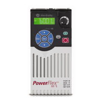
Rockwell Automation Allen-Bradley PowerFlex PF 525 User Manual (272 pages)
Adjustable Frequency AC Drive
Brand:
Rockwell Automation
| Category:
DC Drives
| Size: 33 MB
Table of Contents
Table of Contents
3
About this Publication
9
Download Firmware, AOP, EDS, and Other Files
9
Preface
9
Summary of Changes
9
Additional Resources
10
Download Files
10
Who Should Use this Manual
10
Manual Conventions
11
Drive Frame Sizes
12
General Precautions
13
Catalog Number Explanation
14
Chapter 1 Mounting Considerations
15
Installation/Wiring
15
Minimum Mounting Clearances
16
Ambient Operating Temperatures
17
Current Derating Curves
17
Debris Protection
18
Storage
18
AC Supply Source Considerations
19
Ungrounded Distribution Systems
19
Input Power Conditioning
20
General Grounding Requirements
20
Ground Fault Monitoring
20
Safety Ground - (PE)
21
Network Ground
21
Motor Ground
21
Shield Termination - SHLD
21
RFI Filter Grounding
22
Fuses and Circuit Breakers
22
Fusing
22
Circuit Breakers
22
Fuses and Circuit Breakers for Powerflex 520-Series Drives
24
Power and Control Module
28
Control Module Cover
30
Power Module Terminal Guard
31
Power Wiring
32
Motor Cable Types Acceptable for 100
32
Reflected Wave Protection
34
Output Disconnect
34
Common Bus/Precharge Notes
35
Power Terminal Block
35
I/O Wiring
36
Motor Start/Stop Precautions
36
Signal and Control Wire Types
36
Maximum Control Wire Recommendations
37
Control I/O Terminal Block
37
Powerflex 523 Control I/O Terminal Block
37
Powerflex 525 Control I/O Terminal Block
41
I/O Wiring Examples
43
Start and Speed Reference Control
48
Start Source and Speed Reference Selection
48
Accel/Decel Selection
49
CE Conformity
51
Low Voltage Directive (2014/35/EU)
51
EMC Directive (2014/30/EU)
51
Machinery Directive (2006/42/EC)
51
ATEX Directive (2014/34/EU)
51
General Considerations
52
Chapter 2 Prepare for Drive Startup
57
Drive Startup Task List
57
Start, Stop, Direction, and Speed Control
59
Variable Torque Fan/Pump Applications
59
Start up
57
Display and Control Keys
59
Control and Navigation Keys
60
Viewing and Editing Parameters
61
Drive Programming Tools
62
Language Support
62
Smart Startup with Basic Program Group Parameters
63
LCD Display with Quickview Technology
65
Using the USB Port
65
Mainsfree Programming
65
Using Drive Startup in CCW or Logix Designer Application
66
Chapter 3 About Parameters
69
Programming and Parameters
69
Parameter Groups
71
Appview Parameter Groups
74
Customview Parameter Group
75
Basic Display Group
76
Basic Program Group
82
Terminal Block Group
88
Communications Group
100
Logic Group
106
Advanced Display Group
109
Advanced Program Group
114
Fault and Diagnostic Group
142
Modified Parameter Group
142
Network Parameter Group
142
Appview Parameter Groups
150
Customview Parameter Group
151
Parameter Cross Reference by Name
152
Chapter 4 Drive Status
157
Faults
157
Fault Indication
158
Manually Clearing Faults
158
Automatically Clearing Faults
158
Auto Restart (Reset/Run)
158
Fault Descriptions
159
Common Symptoms and Corrective Actions
162
Certifications
165
Appendix A
166
Environmental Specifications
166
Technical Specifications
167
Power Specifications
170
Product Selection
173
Appendix B Product Dimensions
184
Adapter Plate Dimensions
197
Optional Accessories and Kits
200
Installing a Communication Adapter
200
Removing a Communication Adapter
201
Appendix C Network Wiring
203
Parameter Configuration
205
Supported Modbus Function Codes
205
Writing (06) Logic Command Data
205
Writing (06) Comm Frequency Command
207
Reading (03) Logic Status Data
208
Reading (03) Drive Error Codes
209
Additional Information
210
Reading (03) and Writing (06) Drive Parameters
210
Reading (03) Drive Operational Values
210
Appendix D Velocity Steplogic Sequence
212
Velocity Steplogic Using Basic Logic Functions
212
Velocity Steplogic Using Timed Steps
212
Timer Function
213
Counter Function
214
Velocity Steplogic Parameters
215
Appendix E
217
Encoder Interface
217
HTL/TTL DIP Switches
218
Encoder and Pulse Train Usage
217
Determine Encoder Pulse Per Revolution (PPR) Specification Based on
219
Speed Resolution
219
Wiring Notes
219
Common Guidelines for All Applications
220
Positioning Overview
220
Positioning Operation
221
Homing Routine
224
Encoder and Position Feedback
225
Use over Communications
226
Setup Notes
227
Appendix F PID Loop
229
Exclusive Control
229
Trim Control
230
PID Set up
229
PID Reference and Feedback
231
Analog PID Reference Signals
232
Scale Function
232
Invert Function
232
PID Deadband
232
PID Preload
233
PID Limits
233
PID Gains
233
Guidelines for Adjusting the PID Gains
234
Appendix G Powerflex 525 Safe-Torque-Off Overview
237
Safe Torque off Function
237
EC Type Examination Certification
238
EMC Instructions
238
Safety Concept
239
Important Safety Considerations
239
Functional Proof Test
240
PFD and PFH Data
240
Safety Reaction Time
240
Using Powerflex 525 Safe-Torque-Off
239
Enabling Powerflex 525 Safe-Torque-Off
241
Wiring
241
Powerflex 525 Safe-Torque-Off Operation
242
Verify Operation
242
Discrepancy Time of the Safety Inputs
242
Connection Examples
243
Example 1 - Safe-Torque-Off Connection with Coast-To-Stop Action
243
SIL 2/PL D
243
Example 2 - Safe-Torque-Off Connection with Controlled Stop
245
Action, SIL 2/PL D
245
Example 3 - Safe-Torque-Off Connection with Coast-To-Stop Action Using External +24V Supply, SIL 3/PL E
246
Powerflex 525 Certification for Safe-Torque-Off
246
Appendix H Establishing a Connection with Ethernet/Ip
247
Ground Connections for Ethernet/Ip Networks
248
Appendix I Induction Motor Tuning Diagrams
249
Adjusting Speed Control Parameters
250
Appendix J
252
Motor Control
252
Motor Data
252
Feedback
253
Stop Mode/Brake Type
253
Direction Test
254
Auto Tune
254
Manual Configuration Using Drive Keypad
256
Additional PM Motor Configuration
257
Additional Setup for Open Loop PM Motor
257
Additional Setup for Closed Loop PM Motor
259
Optional Parameter Adjustments for Optimum Performance
261
Appendix K Control Diagram
263
Synrm Structure
263
Synrm Control Configuration
264
Advertisement
Advertisement
Related Products
Rockwell Automation PowerFlex series
Rockwell Automation Allen Bradley PowerFlex40
Rockwell Automation PowerFlex 6000
Rockwell Automation Allen-Bradley PowerFlex PF 523
Rockwell Automation Allen-Bradley PowerFlex 6000
Rockwell Automation Allen-Bradley PowerFlex Active Front End Series
Rockwell Automation Allen-Bradley PowerFlex AFE
Rockwell Automation Allen-Bradley PowerFlex 755TL Series
Rockwell Automation Allen-Bradley PowerFlex 755TR Series
Rockwell Automation Allen-Bradley PowerFlex 755TM Series
Rockwell Automation Categories
Controller
Control Unit
Power Supply
DC Drives
Industrial Equipment
More Rockwell Automation Manuals
Login
Sign In
OR
Sign in with Facebook
Sign in with Google
Upload manual
Upload from disk
Upload from URL