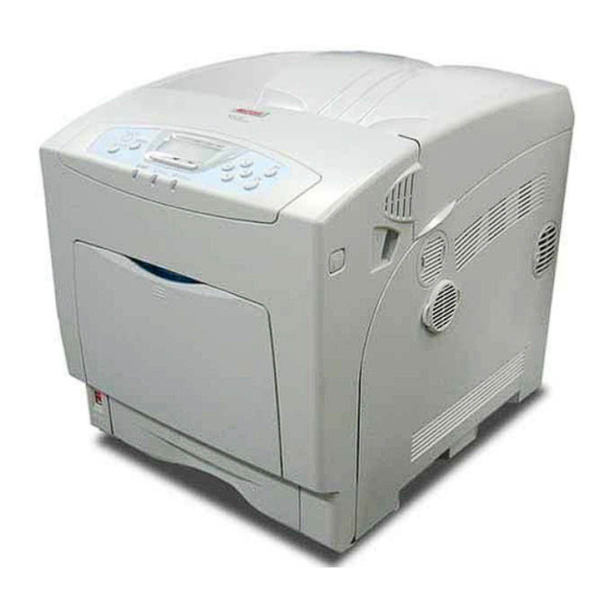
Sign In
Upload
Manuals
Brands
RICOH Manuals
All in One Printer
G104
RICOH G104 Manuals
Manuals and User Guides for RICOH G104. We have
1
RICOH G104 manual available for free PDF download: Service Manual
RICOH G104 Service Manual (601 pages)
G104; G160; G161
Brand:
RICOH
| Category:
All in One Printer
| Size: 16.42 MB
Table of Contents
G104/G160/G161
13
Service Manual
1
Table of Contents
13
Important Safety Notices
21
Laser Safety
22
Symbols and Abbreviations
23
Installation
27
Installation
29
Installation Requirements
31
Environment
31
Machine Level
31
Machine Space Requirement
32
Power Requirements
32
Machine Installation
33
Unpacking
33
Installing the Toner Bottle
35
Loading Paper
37
Connecting the Power Cord
39
Printing the Test Page
40
Selecting the Panel Display Language
40
Optional Unit Installation
41
Meter Charge
42
Tray Heater
43
Preventive Maintenance
45
User Replaceable Items
47
Service Maintenance
48
Recommended Cleaning Procedure
48
Replacement and Adjustment
49
Special Tools and Lubricants
51
Tools
51
Electrical Components
52
Electrical Board Unit
52
Controller Board
54
Iob (Input/Output Board)
54
High Voltage Power Supply Board 1
55
Psu (Power Supply Unit) Board
55
Egb (Engine Board) and High Voltage Power
56
Lcd Panel
56
Supply Board 2
56
Laser Optics
57
Caution Decal Locations
57
Color Registration Adjustment
58
Ld Unit
58
Ldb
60
Polygon Mirror Motor
60
Laser Synchronizing Detector Boards
61
Ldu Shutter Motor Unit and Sensor
61
Paper Feed
62
Paper Feed Roller
62
By-Pass Paper Size Sensor
63
Paper Friction Pad
63
By-Pass Feed Roller, Friction Pad
64
Registration Sensor
65
Paper Volume Sensor, End Sensor and Paper Width Sensor
66
Width Sensor
66
Paper Size Sensor and Temperature/ Humidity Sensor
67
Paper Feed Motor
68
Paper Registration Clutch, Paper Feed Clutch and By-Pass Clutch
69
Development
70
Color Development Motor, Color Opc Motor and Black Opc/Development Motor
70
Development Clutch
70
Toner Supply Motor
71
Transfer Belt Contact Motor
71
Transfer Roller Contact Motor
72
ID Sensors
73
Drive
73
Drive Unit
73
Duplex
74
Duplex Jam Sensor
74
Inverter Sensor
74
Duplex Motor and Inverter Motor
75
Fusing
76
Fusing Unit
76
Thermistor and Thermostat
76
Fusing Lamp
77
Fusing Exit Sensor and Paper Exit Sensor
78
Fusing Registration Sensor
78
Fan Direction
79
Adjustments
80
Gamma Adjustment
80
Troubleshooting
83
Process Control Result
85
Service Call Conditions
86
Engine SC
87
Sc Code Descriptions
87
Controller Error
98
Troubleshooting Guide
105
All-Black Print
105
Blank Print
105
Light Print
106
Missing Cmy Color
106
Dark Vertical Line in Print
107
Repeated Spots or Lines on Prints
107
Dark Irregular Streaks on Prints
108
Dirty Background
108
Missing Parts of Images
108
Partial Cmy Color Dots
108
White Horizontal Lines or Bands
108
Cmy Color Irregular Streaks
109
Ghosting
109
Image Skew
109
Unfused or Partially Fused Prints
109
Image Not Centered When It Should be
110
No Printing on Paper Edge
110
Electrical Component Defects
111
Sensors
111
Blown Fuse Conditions
113
Iob
113
Power Supply Unit
113
Leds
113
Service Tables
115
Service Program Mode
117
Entering the Service Mode
117
Service Mode Operation
117
Accessing the Required Program
118
Exiting Service Mode
118
Inputting a Value or Setting for a Service Program
118
Display on the Control Panel Screen
119
Remarks
119
Others
120
Service Mode Table
121
Controller Service Mode
121
Bit Switch Programming
125
Engine Service Mode
126
SP1-XXX (Feed)
126
SP2-XXX (Drum)
137
SP3-XXX (Process)
163
SP5-XXX (Mode)
173
SP7-XXX (Data Log)
187
SP8-XXX (Data Log 2)
198
Sp9-XXX
208
Input Check Table
212
Output Check Table
214
Firmware Update
216
Handling SD Cards
216
Network Connection
216
Precautions
216
Type of Firmware
216
Upload or Download
216
Example
217
File Arrangement
217
How the Program Works
217
Procedure
218
Updating
218
Error Handling
219
Power Failure
219
Nvram Data Upload/Download
220
Uploading NVRAM Data
220
Downloading NVRAM Data
221
Error Code Table
222
Sd Card Appli Move
223
Overview
223
Move Exec
224
Keeping the SD Card
225
Undo Exec
225
Detailed Section Descriptions
227
Overview
229
Component Layout
229
Paper Path
230
Drive Layout
231
Board Structure
232
Descriptions
233
Printing Process
234
Process Control
236
Overview
236
Overview
237
Potential Control
237
Process Control Self-Check
237
Process Control Self-Check Procedure
239
Step 1: VSG Adjustment
239
Step 2: ID Sensor Solid Pattern Generation
239
Step 3: Sensor Pattern Detection
239
Step 4: Toner Amount Calculation
239
Step 5: VD, VB, VL Selection and VREF Adjustment
240
Toner Supply Control
240
Toner Supply Control Modes
240
Low Image Coverage
241
Introduction
242
Toner Near End/Toner End Detection
242
Toner End Detection
243
Toner End Recovery
243
Toner Near End Detection
243
Developer Initialization
244
Paper Feed
245
Overview
245
Paper Feed Drive
246
Paper Lift
247
Paper Tray
247
Paper Size Detection
248
End Detection
249
Near-End Detection
249
Paper Near End/End Detection
249
Paper Width Sensor
249
By-Pass Tray Feed and Size Detection
250
Duplex
251
Drive
252
Interleaving
253
Laser Exposure
254
Overview
254
Optical Path
255
Laser Synchronizing Detector
256
Main Scan Start Detection
256
Overview
256
Ld Safety Switch
257
Automatic Line Position Adjustment
258
Overview
258
Summary of each Adjustment
259
Adjustment Conditions
260
Main Scan Skew Adjustment
262
LDU Shutter
263
Photoconductor Unit
264
Overview
264
Drive and Drive Gear Position Sensor
265
Mechanism
265
Initialization Process and SC Codes
266
Drum Charge and Quenching
267
Drum Cleaning
268
Waste Toner Collection
269
Waste Toner Bottle Full Detection and Set Detection
270
New Unit Detection
271
Pcu Detection (Development Unit Detection)
271
Unit Set Detection Pins
271
Error Message
272
Development
273
Overview
273
Drive
274
Developer Mixing
275
Development Bias
276
Overview
277
Toner Bottle Detection
277
Toner Supply Mechanism
277
Image Transfer
278
Overview
278
New Transfer Belt Unit Detection
279
Transfer Belt Unit Detection
279
Transfer Unit Detection and New Unit Detection
279
Transfer Belt Drive and Transfer Belt Roller Voltage
280
Transfer Belt Contact
281
Transfer Belt Cleaning
282
Image Transfer
283
Transfer from the Belt
283
Transfer Roller Unit
283
Discharge
284
Transfer Roller Contact
285
Fusing
286
Overview
286
Fusing Temperature Control
287
First Print Temperature: [G]
288
Machine Ready Temperature: [B]
288
Print Ready Temperature: [C]
288
Target Printing Temperature: [D]
288
Overheat Protection
289
Drive
290
Controller
291
Overview
291
Board Layout
293
Specifications
295
General Specifications
297
Supported Paper Sizes
299
Software Accessories
300
Printer Drivers
300
Utility Software
300
Machine Configuration
301
Optional Equipment
302
G160/G161 Section
303
Table of Contents
305
Read this First
309
Safety Notices
309
1 Installation Procedure
315
Installation Requirements
315
Optional Unit Installation
316
2 Preventive Maintenance
317
User Replaceable Items
319
Service Maintenance
320
Recommended Cleaning Procedure
320
3 Replacement and Adjustment
321
Before You Start
323
Laser Optics
324
Caution Decal Locations
324
Ld Unit
324
Fusing
328
Thermistor and Thermostat
328
Electrical Components
331
Controller Board
331
Installing the New Nvram
332
4 Troubleshooting
333
Process Control Results
335
Service Call Conditions
339
Summary
365
Troubleshooting Guide
366
All-Black Print
366
Blank Print
366
Missing Cmy Color
366
Light Print
367
Repeated Spots or Lines on Prints
367
Dark Vertical Line on Prints
368
Cmy Color Irregular Streaks
369
Dark Irregular Streaks on Prints
369
Dirty Background
369
Missing Parts of Images
369
Partial Cmy Color Dots
369
Background Stain
370
Ghosting
370
Image Skew
370
Unfused or Partially Fused Prints
370
Image Not Centered When It Should be
371
No Printing on Paper Edge
371
Electrical Component Defects
372
Sensors
372
Blown Fuse Conditions
376
Iob
376
Power Supply Unit
376
Leds
377
Controller
377
5 Service Tables
379
Service Program Mode
381
Service Mode Operation
381
Remarks
382
Bit Switch Programming
384
Service Mode Table
386
Controller Service Mode
386
Engine Service Mode
390
Input Check Table
539
Output Check Table
542
Firmware Update
545
Precautions
545
Types of Firmware
545
Sd Card Application Move
546
Move Exec
546
Overview
546
Undo Exec
547
Keeping the Sd Card
548
6 Detailed Section Descriptions
549
Before You Begin
551
Overview
552
Component Layout
552
Board Structure
553
Process Control
556
Overview
556
Potential Control
556
Toner Supply Control
559
Toner Near End/Toner End Detection
561
Developer Initialization
562
Paper Feed
563
By-Pass Tray Feed and Size Detection
563
Laser Exposure
564
Ld Safety Switch
564
Automatic Line Position Adjustment
565
Fusing
569
Overview
569
Fusing Temperature Control
570
Corrections for Small Paper Sizes (Less than A)
572
Drive
573
Controller
574
Overview
574
Board Layout
576
7 Specifications
577
Specifications
580
Supported Paper Sizes
582
Software Accessories
583
Machine Configuration
585
Paper Feed Unit Type 4000 G392
589
1 Replacement and Adjustment
591
Paper Feed Unit
591
Paper Feed Motor and Drive Board
592
Drive Board
592
Paper Feed Motor
592
Paper Feed Clutch
593
Sensors
594
Paper End and Paper Near End Sensors
594
Paper End, Paper Near End, and Paper Feed Sensors
594
Paper Feed Sensor
594
Paper Size Detection Switch
594
Paper Feed Roller
595
Friction Pad
595
2 Detailed Descriptions
596
Overall Machine Information
596
Mechanical Component Layout
596
Electrical Component Layout
597
Detailed Descriptions
598
Paper Feed and Separation
598
Paper Lift
599
Paper End Detection
600
Paper Near End Detection
600
Paper Near-End/End Detection
600
Paper Size Detection
601
Advertisement
Advertisement
Related Products
Ricoh g11
Ricoh g12
Ricoh G126
Ricoh G179
RICOH G161
Ricoh G166
Ricoh G184
Ricoh G167
Ricoh G165
Ricoh G181
RICOH Categories
All in One Printer
Printer
Digital Camera
Copier
Printer Accessories
More RICOH Manuals
Login
Sign In
OR
Sign in with Facebook
Sign in with Google
Upload manual
Upload from disk
Upload from URL