Quasonix RDMS Manuals
Manuals and User Guides for Quasonix RDMS. We have 6 Quasonix RDMS manuals available for free PDF download: Installation And Operation Manual, Technical Manual, Firmware Update Procedure
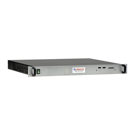
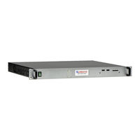
Quasonix RDMS Installation And Operation Manual (251 pages)
Table of Contents
-
Introduction21
-
Description21
-
Nomenclature22
-
Options22
-
Mechanical29
-
Rack-Mount29
-
Touchscreen30
-
Thermal31
-
Electrical31
-
Navigation42
-
Frequency45
-
Mode48
-
AQPSK Mode49
-
Bit Rate49
-
Derandomizer56
-
Hypertrack61
-
AGC Menu62
-
AGC Polarity62
-
AGC Scale63
-
AGC Freeze64
-
Zero AGC66
-
AM Menu67
-
AM Bandwidth68
-
AM Polarity68
-
AM Scale69
-
AGC Comp69
-
Options Menu70
-
IF Filter74
-
DC Antenna80
-
Time Aligner87
-
AFC Mode88
-
PCM Encoding90
-
FEC Menu91
-
Channel a Output100
-
Channel B Output101
-
Test Utilities102
-
Noise Generator102
-
Data Generator103
-
Bert106
-
System Settings111
-
System Info112
-
Ethernet115
-
Web Server118
Advertisement
Quasonix RDMS Installation And Operation Manual (253 pages)
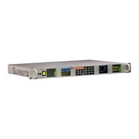
Generation 3rd Rack-Mount Telemetry Receiver
Table of Contents
-
-
Description18
-
Nomenclature19
-
Options19
-
-
-
-
Mechanical26
-
Thermal28
-
Electrical28
-
-
-
Navigation39
-
-
Frequency42
-
Mode44
-
Bit Rate46
-
Derandomizer51
-
AGC Menu56
-
AGC Polarity56
-
AGC Scale57
-
AGC Freeze58
-
Zero AGC59
-
AM Menu61
-
AM Bandwidth62
-
AM Polarity62
-
AGC Comp63
-
AM Scale63
-
Options Menu64
-
IF Filter67
-
DC Antenna74
-
Time Aligner80
-
AFC Mode82
-
PCM Encoding84
-
System Info90
-
Dhcp91
-
FP Version91
-
IP Address91
-
Model91
-
Subnet91
-
Alias92
-
Ethernet92
-
Gateway92
-
Mac92
-
System IP92
-
Graph Type97
-
Signal Strength100
-
-
Network Screen102
-
Monitor Screen104
-
Spectrum Graph108
-
Configure Screen109
-
IF Filter115
-
AFC Mode116
-
Muting Timeout116
-
Output Muting116
-
Time Aligner117
-
PCM Encoding119
-
Channel a Output121
-
Channel a Scale122
-
Channel B Output122
-
Channel B Scale122
-
Mod Scale Index125
-
AGC Polarity127
-
AGC Scale127
-
AGC Freeze128
-
AGC Zero Mode128
-
AM Bandwidth130
-
AGC Compensate131
-
AM Polarity131
-
AM Scale131
-
Zero AGC Button131
-
RSSI Display133
-
Presets134
-
Save Presets134
-
Load Presets139
-
About140
-
Footer Tool Bar141
-
Help141
-
Page Access142
-
Export143
-
Import143
-
-
-
-
Bit Rate - BR178
-
Frequency - FR189
-
Help Command - H189
-
Modulation - MO193
-
Power Level - PL197
-
Tape out - to204
-
Version - VE207
Quasonix RDMS Installation And Operation Manual (190 pages)
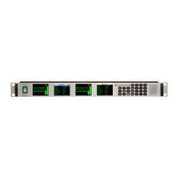
Rack-Mount Telemetry Receiver
Table of Contents
-
-
Description16
-
Nomenclature16
-
-
-
Mechanical24
-
Thermal26
-
Electrical26
-
-
-
-
Navigation33
-
-
Setting Mode38
-
AGC Menu47
-
AM Menu51
-
Options Menu54
-
Status Menu63
-
Network Menu65
-
Dhcp66
-
IP Address66
-
Subnet Mask67
-
-
IF Filter73
-
Video Filter77
-
Video Scale78
-
Video Invert79
-
Tape Output81
-
Muting82
-
DC Antenna88
-
-
Tools Menu118
-
Network Settings119
-
Alias Name120
-
Status120
-
Arrange Windows121
-
Firmware Upgrade122
-
Mission Control122
-
Client Master129
-
Notes132
-
About Menu136
-
File Menu137
-
-
-
Advertisement

Quasonix RDMS Installation And Operation Manual (80 pages)
Status Logger
Brand: Quasonix
|
Category: Data Loggers
|
Size: 4 MB
Table of Contents
-
-
-
-
-
-
Buttons32
-
Setup Name32
-
Channels34
-
Settings36
-
Presets37
-
Log Status41
-
-
-
Exit Menu51
-
Setup Menu51
-
View Menu54
-
Tile Windows54
-
Show Chart59
-
Logging Menu61
-
-

Quasonix RDMS Technical Manual (75 pages)
Brand: Quasonix
|
Category: Controller
|
Size: 0 MB
Table of Contents

Quasonix RDMS Firmware Update Procedure (16 pages)
3rd Generation Rack-Mount Telemetry Receiver