Sign In
Upload
Manuals
Brands
Quantum Manuals
Storage
7000DLT Series
Quantum 7000DLT Series Manuals
Manuals and User Guides for Quantum 7000DLT Series. We have
3
Quantum 7000DLT Series manuals available for free PDF download: Product Manual, Installation And Operation Manual, Supplementary Manual
Quantum 7000DLT Series Product Manual (312 pages)
Tape System
Brand:
Quantum
| Category:
Storage
| Size: 1.92 MB
Table of Contents
Table of Contents
7
Revision History
19
About this Manual
21
Chapter 1: General Description and Specifications
25
Product Description
25
Product Features
26
Product Specifications
26
Physical Specifications
26
Table 1-1 DLT 7000 Physical Dimensions
26
Interface Type
27
Storage Capacity
27
Reliability (Projected)
27
Table 1-2 DLT 7000 Storage Capacity
27
Performance Data
28
Table 1-3 DLT 7000 Performance Data
28
Environmental Specifications
29
Table 1-4 DLT 7000 Environmental Specifications
29
Table 1-5 DLT 7000 Storage and Shipping Specifications
29
Table 1-6 DLT 7000 Operating Shock and Vibration Specifications
30
Table 1-7 DLT 7000 Non-Operating Shock and Vibration Specifications
31
Power Requirements
32
Table 1-8 DLT 7000 Power Requirements
32
Current Requirements
33
Table 1-9 DLT 7000 Current Requirements
33
Acoustic Noise Emissions
34
Tape System Recording Type
34
Table 1-10 Acoustic Noise Emissions, Nominal
34
Table 1-11 Acoustic Noise Emissions for German Noise Declaration Law
34
Dlttape Recording Media Specifications
35
Table 1-12 Dlttape Media Specifications
35
Table 1-13 Dlttape Cartridge Operating and Storage Limits
35
Electromagnetic Emissions
36
Electromagnetic Interference (EMI) Susceptibility
36
Conducted Emissions
36
Table 1-14 EMI Regulations and Certifications
36
Table 1-15 Conducted Emissions
36
Radiated Emissions
37
Susceptibility
37
Table 1-16 Radiated Emissions
37
Table 1-17 Radiated, Magnetic Radiated, and Conducted Susceptibility
37
Chapter 2 : Configuring, Installing, and Operating the Tape Drive
39
Safety, Handling and Electrostatic Discharge (Esd) Protection
39
Safety Precautions
40
Handling
40
Electrostatic Discharge (ESD) Protection
41
Configuring and Installing a Rackmount Tape Drive
41
Setting the Rackmount Drive SCSI ID
42
Figure 2-1 DLT 7000 SCSI ID Jumper Location (Rackmount Version Shown)
43
Table 2-1 SCSI ID Address Selections
43
Configure the Rackmount Drive for TERMPWR (Single-Ended Only)
44
Configure the Rackmount Drive for Parity Checking
44
Figure 2-2 DLT 7000 TERMPWR and Parity Check Jumper Locations
44
Installing the Rackmount Tape Drive
45
Figure 2-3 Rackmount Drive Mounting Locations - Side and Bottom Views
46
Figure 2-4 SCSI and Power Cable Connectors (Rackmount Version Shown)
47
Table 2-2 68-Pin Single-Ended Version SCSI Connector Signal Names
48
Table 2-3 68-Pin Differential Version SCSI Connector Signal Names
49
Figure 2-5 Loader Connector Block Location (Rackmount Version Shown)
50
Table 2-4 4-Pin Power Connector Pin Assignments
50
Table 2-5 10-Pin Loader Connector Pin Assignments
50
Configuring and Installing a Tabletop Tape Drive
51
Configuring the Tabletop Drive
51
Figure 2-6 Tabletop Back Panel
51
Installing the Tabletop Drive
52
Figure 2-7 AC Power Cord Connector Types
53
Drive Controls and Light Emitting Diodes (Leds)
54
Front Panel Controls and Leds
54
Figure 2-8 DLT 7000 Front Panel
54
Table 2-6 LED Functionality
55
Table 2-7 Density LED Functionality
57
Table 2-8 Control Functionality
58
Selecting Density
59
Power on Self Test (POST)
61
Table 2-9 LED Activity During Density Selection
61
Table 2-10 Post/Media Ready Activity
62
Table 2-11 Tape Drive States Following Initialization
62
Troubleshooting
63
Table 2-12 Troubleshooting Chart
63
Chapter 3: SCSI DESCRIPTION
65
SCSI Overview
65
SCSI Commands
66
Table 3-1 Implemented ANSI SCSI-2 Commands
66
Signal States
68
Signal Values
68
SCSI ID Bits
69
Table 3-2 Signal Sources
69
SCSI Signals
70
SCSI Signal Definitions
70
Table 3-3 SCSI-2 Bus Signal Definitions
70
Signal Bus Timing
71
Table 3-4 SCSI Bus Timing Values
71
SCSI Bus Phases
74
BUS FREE Phase
74
ARBITRATION Phase
76
SELECTION Phase
77
RESELECTION Phase
79
Information Transfer Phases
81
Table 3-5 Information Transfer Phases
83
Table 3-6 Status Bytes
87
SCSI Bus Conditions
88
Attention Condition
88
Reset Condition
89
Table 3-7 Drive MESSAGE out Phase Response
89
Queued Unit Attentions
90
Chapter 4: MESSAGES
91
Message Format
91
Table 4-1 Message Format
92
Table 4-2 Supported Messages
93
Figure 4-1 Extended Message - Data Format
94
Table 4-3 Extended Message - Field Description
94
Supported SCSI Messages
95
ABORT Message (06H)
95
BUS DEVICE RESET Message (0Ch)
95
COMMAND COMPLETE Message (00H)
95
DISCONNECT Message (04H)
96
Table 4-4 Drive Response to DISCONNECT Message
96
IDENTIFY Message (80H - Ffh)
97
Figure 4-2 IDENTIFY Message - Data Format
97
Table 4–5 IDENTIFY Message — Field Description
97
IGNORE WIDE RESIDUE Message (23H)
98
Figure 4-3 IGNORE WIDE RESIDUE Message - Data Format
98
INITIATOR DETECTED ERROR Message (05H)
99
Table 4–7 Drive Response to INITIATOR DETECTED ERROR Message
99
LINKED COMMAND COMPLETE Message (0Ah)
100
LINKED COMMAND COMPLETE, with Flag Message (0Ah)
100
MESSAGE PARITY ERROR Message (09H)
100
MESSAGE REJECT Message (07H)
100
NO OPERATION (08H)
101
RESTORE POINTERS Message (03H)
101
SAVE DATA POINTER Message (02H)
101
SYNCHRONOUS DATA TRANSFER REQUEST Message (01H)
101
Figure 4-4 Synchronous Data Transfer Request Message - Data Format
102
WIDE DATA TRANSFER REQUEST Message (01H)
103
Quantum DLT 7000 Tape System
103
Figure 4-5 Wide Data Transfer Request Message - Data Format
103
Chapter 5 : SCSI COMMANDS
105
Overview of Command and Status Processing
105
SCSI Pointers
107
Command Descriptor Block
108
Figure 5-1 Typical Command Descriptor Block - Data Format
108
Status/Error Reporting
110
Figure 5-2 Command Descriptor Block Control Field - Data Format
110
DATA-Phase Command Components
112
Unit Attention Condition
114
Behavior at Power-On and SCSI Bus Reset
115
Data Cache and Tape Write Interaction
115
ERASE Command (19H)
118
Figure 5-3 ERASE Command Descriptor Block - Data Format
118
INQUIRY Command (12H)
119
Figure 5-4 INQUIRY Command Descriptor Block - Data Format
119
Standard Inquiry Data Page
120
Figure 5-5 Standard Inquiry Data Page - Data Format
121
Vendor Unique Inquiry Data
123
Figure 5-6 INQUIRY Vendor Unique Bytes Definitions
124
Figure 5-7 Supported Vital Product Data Pages Page - Data Format
126
Supported Vital Product Data Page
126
Figure 5-8 Unit Serial Number Page (80H)- Data Format
127
Figure 5-9 Firmware Build Information Page (VU) (C0H)- Data Format
128
Figure 5-10 Subsystem Components Revision Page (C1H) - Data Format
129
LOAD UNLOAD Command (1Bh)
131
Figure 5-11 LOAD UNLOAD Command Descriptor Block - Data Format
132
LOCATE Command (2Bh)
134
Figure 5-12 LOCATE Command Descriptor Block - Data Format
134
LOG SELECT Command (4Ch)
136
Figure 5-13 LOG SELECT Command Descriptor Block - Data Format
136
Descriptor Block
138
Log Detection Summary in LOG SELECT Command
138
Operation of LOG SELECT
138
Figure 5-14 LOG SELECT Log Page Header Format
139
Log Select Page Format
139
Figure 5-15 LOG SELECT Log Parameters Format
140
Error Detection Summary in LOG SELECT Pages
142
LOG SENSE Command (4Dh)
143
Figure 5-16 LOG SENSE Command Descriptor Block - Data Format
143
Error Detection Summary in LOG SENSE Command Descriptor Block
146
Figure 5-17 Supported Pages Page - Data Format
147
Supported Pages Log Page (Page 00H)
147
Figure 5-18 Read/Write Error LOG SENSE Header Format
148
Figure 5-19 Log Parameters Format for Read/Write Error LOG SENSE Page
149
Figure 5-20 Last N Error Events LOG SENSE Header Format
152
Last N Error Events Page (07H)
152
Figure 5-21 Log Parameters Format for Last N Error Events LOG SENSE Page
153
Figure 5-22 Tapealert LOG SENSE Header Format
154
Tapealert Page (2Eh)
154
Figure 5-23 Tapealert Page Log Parameters Format
155
Figure 5-24 Read/Write Compression Ratio LOG SENSE Header Format
158
Read / Write Compression Page (32H)
158
Device Wellness Page (33H)
163
Device Status Page (3Eh)
166
Mode Parameter List
171
READ / WRITE Error Recovery Page (01H)
177
Disconnect / Reconnect Page (02H)
179
Control Mode Page (0Ah)
182
Data Compression Page (0Fh)
184
Device Configuration Page (10H)
186
Medium Partition Page (11H)
189
Tapealert Page (1Ch)
191
EEPROM Vendor Unique Page (3Eh)
194
Changeable Parameters Within MODE SELECT
204
MODE SENSE (6) / (10) Command (1Ah / 5Ah)
205
MODE SENSE Data Headers
208
MODE SENSE Block Descriptor
210
MODE SENSE Mode
212
PREVENT / ALLOW MEDIUM REMOVAL Command (1Eh)
231
READ Command (08H)
232
READ BLOCK LIMITS Command (05H)
235
READ BUFFER Command (3Ch)
237
Combined Header and Data Mode
239
Data Mode
239
Descriptor Mode
240
READ POSITION Command (34H)
241
RECEIVE DIAGNOSTIC RESULTS Command (1Ch)
244
RELEASE UNIT Command (17H)
246
REQUEST SENSE Command (03H)
248
RESERVE UNIT Command (16H)
259
REWIND Command (01H)
261
SEND DIAGNOSTIC Command (1Dh)
262
SPACE Command (11H)
267
TEST UNIT READY Command (00H)
269
VERIFY Command (13H)
270
WRITE Command (0Ah)
272
WRITE BUFFER Command (3Bh)
274
Write Combined Header and Data Mode (000B)
275
Write Data Mode (010B)
275
Download Microcode Mode (100B)
276
Download Microcode and Save Mode (101B)
276
WRITE FILEMARKS Command (10H)
277
Data Format
277
Descriptions
277
Table A–1 Internal Status Codes
279
Appendix A: Definition of Vendor Unique Sense Data Information
280
Figure A-1 Internal Status Bits
282
Table A–2 Internal Status Bit Flags
282
Appendix B: EEPROM-Resident Bugcheck and Event Logs
283
EEPROM Packets (LAST N EVENTS
283
Bugcheck Packets
284
POST Failure Packets
284
Table B–1 Bugcheck Packet Error Codes (Bytes 9 - 10)
284
Event Log Packets
285
Table B–2 Event Log Error Codes (Bytes 9 - 10)
285
Directory Failure Event Log Packets
286
Table B–3 Directory Failure Event Package — Field Descriptions
286
Appendix C: Updating the Firmware
287
Overview
287
C.2 Creating a Firmware Update Tape
287
Table C–1 Block Size Used for Firmware Update Tape
287
Firmware Update Procedure
288
Quantum DLT 7000 Tape System
288
Interpreting the Results of a Firmware Update
290
Appendix D: the Tape Cartridge
294
Tape Cartridge Inspection Procedure
296
Figure D-1 Location of One of the Two Reel Lock Tabs on the Dlttape Cartridge
296
Dlttape Cartridge
297
Correct Position
298
Inspection
299
Tape Cartridge Write-Protect Switch
300
Figure D-5 Write-Protect Switch on Tape Cartridge
300
Table D-1 Write-Protect Switch Positions
301
Loading a Tape Cartridge
302
Unloading a Tape Cartridge
303
Using a Cleaning Tape Cartridge
304
Table D-2 When to Use a Cleaning Tape Cartridge
304
Index
310
Advertisement
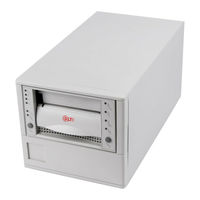
Quantum 7000DLT Series Installation And Operation Manual (88 pages)
Tabletop Series
Brand:
Quantum
| Category:
Storage
| Size: 1.52 MB
Table of Contents
Operation Guide
1
Table of Contents
3
Introduction
11
Associated Documents
11
Explanation of Symbols and Notes
11
Overview
13
Intended Audience
13
Organization
13
Associated Documents
14
Explanation of Symbols and Notes
14
Description
15
Overview
17
Description
17
Front Panel Controls and Indicators
18
Figure 2-1 7000DLT Front Panel
19
Other Requirements
24
SCSI Host Adapter
24
SCSI Interface Cable
25
Application Software
25
Additional Items
25
Safety
29
Safety Conventions
29
Precautions
30
Installation
33
Overview
35
Unpacking and Inspecting
35
Installing the Host Adapter
35
Connecting the Interface Cable
35
Connecting more than One 4000/7000DLT Series
36
Setting the SCSI ID
37
Figure 4-2 SCSI ID Switch
37
Check the SCSI Bus Termination
38
Connecting Power and Turning on
39
Installing the Backup Software
39
Operation and Maintenance
41
Overview
43
Power-On Self-Test
43
Drive Status
44
LED Indicators
44
LCD Messages
45
Drive Operating Conditions
46
LED Indicators
46
LCD Messages
48
Loading the Data Cartridge
52
Data Protection
53
Tape in Use
53
Removing the Data Cartridge
54
Cleaning the Tape Head
55
Cleaning the Enclosure
58
Troubleshooting and Diagnostic
59
Overview
61
Troubleshooting Chart
61
Use Cleaning Tape LED
63
Why the Use Cleaning Tape LED Gets Turned on
64
High Humidity
65
Specification
67
General Specification
67
General Specification
69
Drive Configuration
71
Drive Dependent Configuration
73
SCSI Bus Parity
73
DLT4000 Drives
73
Figure B-1 DLT4000 Tape Drive Connectors (Left Side)
73
Figure B-2 Disable Parity Pins on SCSI ID Connector
73
DLT7000 Drive
74
SCSI Bus Termination and Terminator Power
75
DLT4000 Drives
75
DLT7000 Drives
77
Figure B-7 DLT7000 Tape Drive Connectors (Right Side)
77
Regulatory Notices
79
FCC Notices (U.S. Only
81
Shielded Cables
81
Product Type
82
IC Notice (Canada Only
82
EN 55022 Compliance (Czech Republic Only
83
CE Notice
83
VCCI Notices (Japan Only
84
Quantum 7000DLT Series Supplementary Manual (10 pages)
Quantum DLT 4000: Supplementary Guide
Brand:
Quantum
| Category:
Storage
| Size: 0.24 MB
Table of Contents
Table of Contents
2
Quick Guide
2
Dlttape Cartridges
3
Your Cartridge
3
Cartridge Features
3
Write Protect Switch
3
Media Care Overview
4
Labeling Your Cartridge
4
Proper Storage
4
When Do I Perform
5
A Visual Inspection
5
Visual Inspection
5
Spotting Damaged
7
Dlttape Media and Super Dlttape Media
7
Www.quantum.com
8
Advertisement
Advertisement
Related Products
Quantum 4000 Enhanced
Quantum 4000DLT Series
Quantum 432
Quantum 520G.GS003
Quantum 6-67057-02 Rev A
Quantum A-Series FTP
Quantum ACL 4/52
Quantum ActiveScale P100
Quantum Categories
Storage
Wheelchair
Network Hardware
Server
Wireless Access Point
More Quantum Manuals
Login
Sign In
OR
Sign in with Facebook
Sign in with Google
Upload manual
Upload from disk
Upload from URL