Sign In
Upload
Manuals
Brands
Quanmax Manuals
Motherboard
KEEX-6150 Series
Quanmax KEEX-6150 Series Manuals
Manuals and User Guides for Quanmax KEEX-6150 Series. We have
1
Quanmax KEEX-6150 Series manual available for free PDF download: User Manual
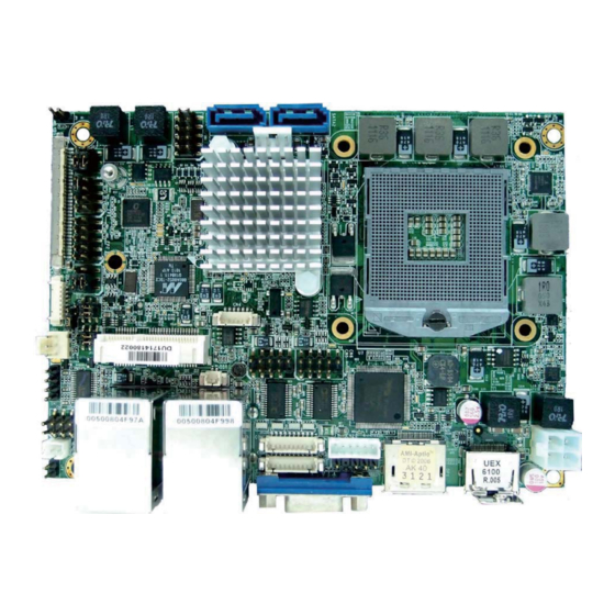
Quanmax KEEX-6150 Series User Manual (59 pages)
Industrial ECX Embedded SBC with 2nd generation Intel core i3/i5/i7 processor
Brand:
Quanmax
| Category:
Motherboard
| Size: 0.87 MB
Table of Contents
Content
3
Table of Contents
3
Figures
5
Tables
6
Before You Begin
8
Safety Instructions
8
When Working Inside a Computer
8
Preventing Electrostatic Discharge
9
How to Use this Guide
11
Preface
11
Regulatory Compliance Statements
11
Unpacking
11
Warranty Policy
12
Maintaining Your Computer
13
Chapter 1 Introduction
16
Overview
16
Product Specifications
17
Table 1 KEEX-6100 Series Specification
18
System Block Diagram
19
Figure 1 Block Diagram
19
Mechanical Dimensions
20
Figure 2 Mechanical Dimensions
21
Chapter 2 Hardware Settings
22
Overview
22
Figure 3 Jumper Connector
22
Jumper Settings and Pin Definitions
23
Figure 4 Jumper and Connector Locations
23
Jumper Settings
24
Table 2 Jumper List
24
Table 3 JP1 ME F/W Selection
24
Table 4 JP2 Panel & Backlight Power Selection for LVDS2
24
Table 5 JP3 Panel Backlight Power Selection for LVDS1
25
Table 6 JP4 Backlight Power Enable Selection for LVDS1
25
Table 7 JP5 Backlight Power Enable Selection for LVDS2
25
Table 8 JP6 AT/ATX Mode Selection
25
Table 9 JP7 SRTC Reset Selection
25
Table 10 JP8 RTC Reset Selection
25
Rear Panel Pin Assignments
26
Figure 5 Rear Panel IO
26
Table 11 Rear Panel Connector List
26
Table 12 CN9 LAN1 & USB 2.0 Port 0, 1 Connector
26
Table 13 CN10 LAN2 & USB 2.0 Port 8, 9 Connector
26
Table 14 DP1 Display Port Connector
27
Table 15 HDMI1 HDMI Connector
27
Table 16 VGA1 DB-15 VGA Connector
27
Main Board Pin Assignments
28
Table 17 Internal Connector List
28
Table 18 ATX2 +12V Power Input Connector
28
Table 19 CR2032 Battery Power Input Wafer
28
Table 20 CFD1 CF Type II Connector
29
Table 21 COM1 RS-232/422/485 Port 1 Wafer
30
Table 22 COM2 RS-232 Port 2 Wafer
30
Table 23 CN1 Digital Input / Output Pin Header
30
Table 24 CN2 SATA HDD Power Output Wafer
30
Table 25 CN3 Backlight Power Output Wafer for LVDS1
31
Table 26 CN4 SIM Interface Wafer for MPCIE1
31
Table 27 CN5 USB 2.0 Port 2, 3 Pin Header
31
Table 28 CN6 USB 2.0 Port 10, 11 Pin Header
31
Table 29 CN7 S/PDIF Pin Header
32
Table 30 CN8 Audio Pin Header
32
Table 31 CN12 Left Channel 2W Audio AMP Output Wafer
32
Table 32 CN13 Right Channel 2W Audio AMP Output Wafer
32
Table 33 CN14 Backlight Power Output Wafer for LVDS2
32
Table 34 CN20 Keyboard & Mouse Wafer
33
Table 35 DIMM1 DDR3 Memory SO-DIMM Socket
33
Table 36 FAN1 CPU FAN Wafer
33
Table 37 FP1 Front Panel 1 Pin Header
33
Table 38 FP2 Front Panel 2 Pin Header
33
Table 39 IR1 Irda Pin Header
33
Table 40 LVDS1 Primary 24-Bit, 2-Channel LVDS Panel Connector
34
Table 41 LVDS2 Secondary 24-Bit, 2-Channel LVDS Panel Connector
34
Table 42 MPCIE1 Mini-PCIE Express V 1.2 Socket
35
Table 43 SATA1 Serial ATA Port 0 Connector
36
Table 44 SATA2 Serial ATA Port 1 Connector
36
Chapter 3 System Installation
37
Expansion Interfaces
37
Memory Module Installation
37
Figure 6 Align the SO-DIMM Memory Module with the Onboard Socket
37
Figure 7 Press down on the SO-DIMM Memory Module to Lock It in Place
38
Chapter 4 AMI BIOS Setup
39
Overview
39
Main Menu
40
Table 45 BIOS Main Menu
40
Advanced Menu
41
Table 46 Advanced Menu
41
Table 47 Advanced Menu - Display Configuration
42
Table 48 Advanced Menu - Super IO Configuration
43
Table 49 Advanced Menu - Super IO Configuration - Serial Port
44
Table 50 Advanced Menu - Super IO Configuration - Serial Port
44
Table 51 Advanced Menu -Power Management Configuration
45
Table 52 Advanced Menu -CPU Advanced Configuration
46
Table 53 Advanced Menu -Trusted Computing
47
Table 54 Advanced Menu -SATA Configuration
47
Table 55 Advanced Menu -Intel TXT(LT) Configuration
48
Table 56 Advanced Menu - AMT Configuration
48
Table 57 Advanced Menu -USB Configuration
50
Table 58 Advanced Menu -H/W Monitor
51
Boot Menu
52
Table 59 Boot Menu
52
Security Menu
53
Save & Exit Menu
53
Table 60 Security Menu
53
Table 61 Save & Exit Menu
53
Advertisement
Advertisement
Related Products
Quanmax KEEX-6100
Quanmax KEEX-4030
Quanmax KEEX-2010
Quanmax KEEX-1850 Series
Quanmax KEEX-8100 Series
Quanmax KEMX-6000
Quanmax KEMX-1750 series
Quanmax KEMB-8100 series
Quanmax KEMB-8000 Series
Quanmax KEMX-1600 Series
Quanmax Categories
Desktop
Touch Panel
Motherboard
Computer Hardware
Monitor
More Quanmax Manuals
Login
Sign In
OR
Sign in with Facebook
Sign in with Google
Upload manual
Upload from disk
Upload from URL