Sign In
Upload
Manuals
Brands
Quanmax Manuals
Motherboard
KEEX-1850 Series
Quanmax KEEX-1850 Series Manuals
Manuals and User Guides for Quanmax KEEX-1850 Series. We have
1
Quanmax KEEX-1850 Series manual available for free PDF download: User Manual
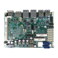
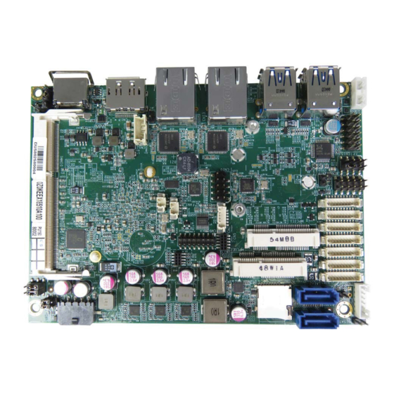
Quanmax KEEX-1850 Series User Manual (61 pages)
Standard/Extended Temperature Single Board Computer in Intel Embedded Compact Extended Form Factor with Intel Braswell SoC Processor
Brand:
Quanmax
| Category:
Motherboard
| Size: 0.85 MB
Table of Contents
Table of Contents
3
Content
3
Figures
5
Tables
6
Safety Instructions
8
Before You Begin
8
When Working Inside a Computer
8
Preventing Electrostatic Discharge
9
Preface
11
How to Use this Guide
11
Unpacking
11
Regulatory Compliance Statements
11
Warranty Policy
12
Maintaining Your Computer
13
Chapter 1 Introduction
16
Overview
16
Product Specifications
17
System Block Diagram
18
Figure 1 Block Diagram
18
Table 1 KEEX-1850 Series Specification
18
Mechanical Dimensions
19
Figure 2 Mechanical Dimensions
19
Chapter 2 Hardware Settings
20
Overview
20
Figure 3 Jumper Connector
20
Jumper Settings and Pin Definitions
21
Figure 4 Jumper and Connector Locations
21
Jumper Settings
22
Table 2 Jumper List
22
Table 3 JP1 RTC Reset Selection
22
Table 4 JP2 Backlight Enable Selection
22
Table 5 JP3 MPCIE Activity LED Indication
22
Table 10 JP9 at / ATX Power Mode Selection
23
Table 6 JP4 Panel & Backlight Power Selection
23
Table 7 JP6 USB Power Selection
23
Table 8 JP7 ME F/W Selection
23
Table 9 JP8 Keyboard Lock Selection
23
Internal Connector Pin Assignment
24
Table 11 Internal Connector Pin List
24
Table 12 BAT1 CR2032 Battery Power Input Wafer
25
Table 13 CN1 DC12V Power Input Wafer
25
Table 14 CN1 DC12V Power Input Wafer
25
Table 15 CN3 Secondary 18/24-Bit, 2-Channel LVDS Panel Connector
26
Table 16 CN4 PS/2 Keyboard / Mouse Wafer
26
Table 17 CN6 VGA Header
26
Table 18 CN7 SIM Interface Wafer for MPCIE1
27
Table 19 CN10 USB2.0 Port DN_1, DN_2 Pin Header
27
Table 20 CN11 Digital Input / Output Wafer
27
Table 21 CN12 HDD Power Output Wafer
27
Table 22 CN15 Audio Input / Output Pin Header
28
Table 23 CN16 Left Channel 3W Audio AMP Output Wafer
28
Table 24 CN19 Right Channel 3W Audio AMP Output Wafer
28
Table 25 CN20 COM1 RS-232/422/485 Port Wafer
28
Table 26 CN21 COM2 RS-232/422/485 Port Wafer
29
Table 27 CN22~CN25 COM3~6 RS-232 Port Wafer
29
Table 28 CN14 Backlight Power Output Wafer
29
Table 29 FAN1 DC5V FAN Wafer
30
Table 30 FP1 Front Panel 1 Pin Header
30
Table 31 FP2 Front Panel 2 Pin Header
30
Table 32 MPCIE1 Mini-PCI Express V1.2 Socket
31
Table 33 MPCIE2 Mini-PCI Express V1.2 Socket
32
Table 34 SATA1 Serial ATA Port 0 Connector
32
Table 35 SATA2 Serial ATA Port 1 Connector
32
Figure 5 Rear Panel IO
33
Rear Panel Pin Assignments
33
Table 36 Rear Panel Connector List
33
Table 37 CN13 Gbe LAN1 RJ-45 Connector
33
Table 38 CN14 Gbe LAN2 RJ-45 Connector
33
Table 39 CN8 USB3.0 Port-0,1 Type-A Connector
34
Table 40 CN9 USB3.0 Port-2,3 Type-A Connector
34
Table 41 CN17 Displayport Connector
34
Table 42 CN18 HDMI Connector
35
Chapter 3 System Installation
36
Memory Module Installation
36
Figure 6 Align the SO-DIMM Memory Module with the Onboard Socket
36
Figure 7 Press down on the SO-DIMM Memory Module to Lock It in Place
37
Removing a DIMM
37
Chapter 4 AMI BIOS Setup
38
Overview
38
Main Menu
39
Table 43 BIOS Main Menu
39
Advanced Menu
40
Table 44 Advanced Menu
40
Table 45 Advanced Menu - Display Configuration
41
Table 46 Advanced Menu - Super IO Configuration
42
Table 47 Advanced Menu - Super IO Configuration - Serial Port
42
Change Settings
42
Table 48 Advanced Menu - Super IO Configuration - Serial Port
43
Table 49 Advanced Menu - Super IO Configuration - Serial Port
44
Table 50 Advanced Menu - Super IO Configuration - Serial Port
45
Table 51 Advanced Menu - Super IO Configuration - Serial Port
46
Table 52 Advanced Menu - Super IO Configuration - Serial Port
46
Intel Virtualization Technology
47
Limit Cpuid Maximum
47
Table 53 Advanced Menu - CPU Chipset Configuration
47
Table 54 Advanced Menu - SATA Configuration
48
Sata Controller
48
Legacy Usb Support
49
Table 55 Advanced Menu - USB Configuration
49
Usb Mass Storage Driver Support
49
Table 56 Advanced Menu - DIO Configuration
50
Cpu Warning Temperature
51
Smart Fan Configuration
51
Table 57 Advanced Menu - H/W Monitor
51
Acpi Sleep State
52
Table 58 Power Manu
52
Watchdog Timer Configuration
52
Wdt Function
52
Security Menu
53
Table 59 Security Menu
53
Boot Menu
54
Table 60 Boot Menu
54
Save & Exit Menu
55
Table 61 Save & Exit Menu
55
Chapter 5 Driver Installation
56
Watchdog Timer Sample Code
60
Advertisement
Advertisement
Related Products
Quanmax KEEX-6100
Quanmax KEEX-4030
Quanmax KEEX-2010
Quanmax KEEX-8100 Series
Quanmax KEEX-6150 Series
Quanmax KEMF-4010
Quanmax KEMX-6000
Quanmax KEMX-1600 Series
Quanmax KEMX-8000 Series
Quanmax KEMX-1750 series
Quanmax Categories
Desktop
Touch Panel
Motherboard
Computer Hardware
Monitor
More Quanmax Manuals
Login
Sign In
OR
Sign in with Facebook
Sign in with Google
Upload manual
Upload from disk
Upload from URL