Sign In
Upload
Manuals
Brands
Quanmax Manuals
Single board computers
ECX-APL0 Series
Quanmax ECX-APL0 Series Manuals
Manuals and User Guides for Quanmax ECX-APL0 Series. We have
1
Quanmax ECX-APL0 Series manual available for free PDF download: User Manual
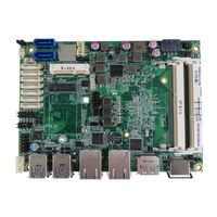
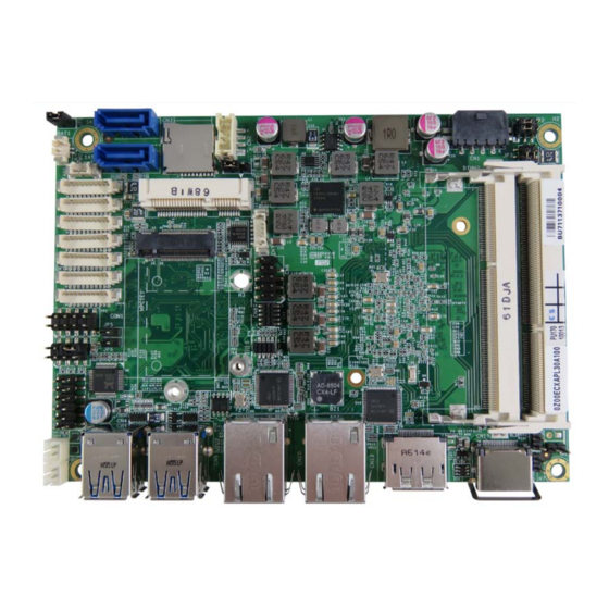
Quanmax ECX-APL0 Series User Manual (65 pages)
3.5" ECX Single Board Computer with Intel Apollo Lake SoC Processors
Brand:
Quanmax
| Category:
Single board computers
| Size: 1.39 MB
Table of Contents
Table of Contents
3
Content
3
Figures
5
Tables
6
Safety Instructions
8
Before You Begin
8
When Working Inside a Computer
8
Preventing Electrostatic Discharge
9
Preface
11
How to Use this Guide
11
Unpacking
11
Regulatory Compliance Statements
11
Warranty Policy
12
Maintaining Your Computer
13
Chapter 1 Introduction
16
Overview
16
Product Specifications
17
Table 1 Product Specifications
17
System Block Diagram
18
Figure 1 Block Diagram
18
Mechanical Dimensions
19
Figure 2 Mechanical Dimensions
19
Chapter 2 Hardware Settings
20
Overview
20
Figure 3 Jumper Connector
20
Jumper Settings and Pin Definitions
21
Figure 4 Jumper and Connector Locations
21
Jumper Settings
22
Table 2 Jumper List
22
Table 3 JP1 SIM CARD SELECTION
22
Table 4 JP2 Backlight Enable Selection
22
Table 5 JP3 Panel & Backlight Power Selection
22
Table 6 JP4 at / ATX Power Mode Selection
23
Table 7 JP5 M2 KEY B LED Pin Header
23
Table 8 JP6 MPCIE Activity LED Pin Header
23
Table 9 JP8 RTC Reset Selection
23
Table 10 JP9 USB Power Selection
23
Table 11 JP10 ME F/W Selection
23
Internal Connector Pin Assignment
24
Table 12 BAT1 CR2032 Battery Power Input Wafer
25
Table 13 CN1 DC12V Power Input Wafer
25
Table 14 CN2 HDD Power Output Wafer
25
Table 15 CN3 Micro-SD Card Cage
25
Table 16 CN6 USB2.0 Port DN_1, DN_2 Pin Header
25
Table 17 CN7 SIM Interface Wafer for MPCIE1 and M2 KEY B
26
Table 18 CN11 Audio Input / Output Pin Header
26
Table 19 CN12 Left Channel 3W Audio AMP Output Wafer
26
Table 20 CN14 Digital Input / Output Wafer
26
Table 21 CN16 Right Channel 3W Audio AMP Output Wafer
27
Table 22 CN17 COM1 RS-232/422/485 Port Wafer
27
Table 23 CN18 COM2 RS-232/422/485 Port Wafer
27
Table 24 CN19~CN22 COM3~6 RS-232 Port Wafer
28
Table 25 CN23 Backlight Power Output Wafer
28
Table 26 LVDS1 18/24-Bit, 1/2-Channel LVDS Panel Connector
28
Table 27 FAN1 DC5V FAN Wafer
29
Table 28 FP1 Front Panel 1 Pin Header
29
Table 29 FP2 Front Panel 2 Pin Header
29
Table 30 MPCIE1 Mini-PCI Express V1.2 Socket (Full Size)
30
Table 31 CON1 NGFF M.2 KEY B Socket
31
Table 32 SATA1 Serial ATA Port 0 Connector
32
Table 33 CN26 USB2.0 Port Wafer (Option)
32
Rear Panel Pin Assignments
33
Figure 5 Rear Panel IO
33
Table 34 Rear Panel Connector List
33
Table 35 CN9 Gbe LAN1 RJ-45 Connector
33
Table 36 CN10 Gbe LAN2 RJ-45 Connector
33
Table 37 CN4 USB3.0 Port-0,1 Type-A Connector
34
Table 38 CN5 USB3.0 Port-2,3 Type-A Connector
34
Table 39 CN13 Displayport Connector
34
Table 40 CN15 HDMI Connector
35
Chapter 3 System Installation
36
Memory Module Installation
36
Figure 6 Align the SO-DIMM Memory Module with the Onboard Socket
36
Figure 7 Press down on the SO-DIMM Memory Module to Lock It in Place
37
Chapter 4 AMI BIOS Setup
38
Overview
38
Main Menu
39
Table 41 BIOS Main Menu
39
Advanced Menu
40
Table 42 Advanced Menu
40
Table 43 Advanced Menu - Display Configuration
41
Table 44 Advanced Menu - Super IO Configuration
42
Table 45 Advanced Menu - Super IO Configuration - Serial Port
42
Table 46 Advanced Menu - Super IO Configuration - Serial Port
43
Table 47 Advanced Menu - Super IO Configuration - Serial Port
44
Table 48 Advanced Menu - Super IO Configuration - Serial Port
45
Table 49 Advanced Menu - Super IO Configuration - Serial Port
46
Table 50 Advanced Menu - Super IO Configuration - Serial Port
47
Table 51 Advanced Menu - CPU Chipset Configuration
48
Table 52 Advanced Menu - SATA Configuration
49
Table 53 Advanced Menu - USB Configuration
50
Table 54 Advanced Menu - DIO Configuration
51
Table 55 Advanced Menu - Network Stack
52
Table 56 Advanced Menu - H/W Monitor
53
Power Menu
54
Table 57 Power Configuration
54
Boot Menu
55
Table 58 Boot Menu
55
Security Menu
56
Table 59 Security Menu
56
Save & Exit Menu
57
Table 60 Save & Exit Menu
57
Chapter 5 Driver Installation
59
Advertisement
Advertisement
Related Products
Quanmax ECX-BW00
Quanmax ECX-SLU0 Series
Quanmax ECX-KLU0 Series
Quanmax Categories
Desktop
Touch Panel
Motherboard
Computer Hardware
Monitor
More Quanmax Manuals
Login
Sign In
OR
Sign in with Facebook
Sign in with Google
Upload manual
Upload from disk
Upload from URL