Sign In
Upload
Manuals
Brands
Precision Digital Corporation Manuals
Controller
PD9000-GP-4AI
Precision Digital Corporation PD9000-GP-4AI Manuals
Manuals and User Guides for Precision Digital Corporation PD9000-GP-4AI. We have
3
Precision Digital Corporation PD9000-GP-4AI manuals available for free PDF download: Instruction Manual, Manual
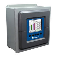
Precision Digital Corporation PD9000-GP-4AI Instruction Manual (99 pages)
Multivariable Controller
Brand:
Precision Digital Corporation
| Category:
Controller
| Size: 6 MB
Table of Contents
Table of Contents
3
Introduction
7
Ordering Information
7
Add-On Features
8
Input / Output Cards
8
Setup & Calibration Services
8
Enclosures
8
Accessories
9
Specifications
12
General
12
Totalizer
14
Real Time Clock
14
Channel & Math Functions
15
List of Engineering Units
16
4-20 Ma Analog Inputs
17
Pulse Inputs
17
Modbus Inputs - Server
18
Digital Inputs & Outputs
18
Relays
18
4-20 Ma Transmitter Outputs
19
Timers
19
Modbus Outputs - Server
19
Modbus Serial Communications
20
Client & Snooper Settings
20
Spoofer Settings
20
Ethernet Communications
21
Consolidator+ Software
21
Safety Information
21
Installation
21
Unpacking
21
Panel Mounting
22
Figure 1. Front Panel Mount Dimensions
22
Figure 2. Panel Cutout Dimensions
22
Mounting Dimensions
23
Figure 3. Panel Mount Installation
23
Figure 4. Panel Mount Overall Dimension
23
Consolidator+ Configuration Software Installation
24
Consolidator+ Software
25
Connections
26
Figure 5. Connection Terminals for a PD9000-GP-4PI-8AI-10AO-10RY
26
Power Connections
27
Figure 6. Power Connections
27
Figure 7. Transmitters Powered by Consolidator+ Isolated 24 VDC Power Supply
27
Figure 8. Transmitter Powered by Ext. Supply or Self-Powered
27
Figure 9. 3-Wire Transmitters Powered Externally
27
Analog Output Connections
28
Digital Output Connections
28
Figure 10. Flow Meter Pulse Input Connections
28
Figure 11. Digital Input from Switch Closure and Live Signal
28
Figure 12. Active 4-20 Ma Output Powered by Controller
28
Figure 13. Passive 4-20 Ma Output Powered by External Supply
28
Figure 14. Digital Outputs Driving 5 V Solid State Relay
28
Connections to Power Gas Detector
29
Figure 15. Two Supplies in Parallel Powering 3-Wire Transmitter
29
Figure 16. Powering 4-Wire Gas Detector & Isolated 4-20 Ma Output
29
Serial Communication Connections
30
External Keypad Connections
30
Figure 17. Relay Connections
30
Figure 18. AC and DC Internal Inductive Loads Protection
30
Figure 19. Low Voltage DC Loads Protection
30
Figure 20. Serial Connections
30
Figure 21. External Keypad Connections
30
Navigating and Editing
31
Soft-Keys and Buttons
31
Setup and Programming
32
Overview
32
Setup Menu
33
Channel Parameters
34
Data Entry Keypad
35
Setup Channels
36
Create New Channel
37
Bargraph, Background & Text Colors
38
Live Calibration
39
Edit Channel
39
Delete Channel
39
2-Point Linear Scaling
40
Square Root Scaling
40
Figure 22. Linear Response Graph
40
Figure 23. Square Root Response Graph
40
Scale Exponent
41
Round Horizontal Tank
41
Figure 24. Exponent Response Graph
41
Figure 25. Round Horizontal Tank Volume Graph
41
Open Channel Flow Application
42
Figure 26. Total Relay Sampling Operation
42
Setup Math Functions
43
Open Channel Flow
45
Setup Totalizers
46
Setup Total with Pulse Input Source
46
Setup Accumulated Total (Triggered)
47
Setup Previous Total
47
Setup Daily Total
47
Setup Grand Total
48
Setup Timers
49
Setup Alarms
50
Logic or Alarm
51
Logic and Alarm
51
Logic nor & NAND Alarms
51
Day & Time Alarms
52
Setup Inputs
53
Setup 4-20 Ma Inputs
53
Setup Pulse Inputs
54
Setup Digital Inputs
54
Modbus Functionality
56
Setup Modbus Inputs (Server)
56
Setup Modbus Inputs (Client)
57
Setup Modbus Inputs (Snooper)
57
Setup All Outputs
58
Setup 4-20 Ma Outputs
58
Setup Relay Output
59
Setup Digital Output
61
Setup Modbus Output (Server)
61
Setup Modbus Output (Client)
62
Setup Modbus Output (Spoofer)
63
Setup Screens
64
Screens Settings
64
Setup System
66
Setup Display
66
Setup Colors
66
Display Settings
66
General Settings
67
Add-On Features
67
Set Password
68
Password Protected Controller
68
Remove Password Protection
68
System Date & Time
69
System Build
69
Modbus Server Settings
70
Modbus Client Settings
70
Modbus Snooper Settings
70
Ethernet Settings
71
Manually Assigned IP Address
71
Custom Units
72
Delete Custom Units
72
Ethernet Port Setup - Full
73
Test Ethernet Communication
75
View Menu
76
View Channel Details
76
View Associated Parameters
77
View Alarm Details
77
View Totals
78
Totals Generated by Non-Rate Inputs
79
View Timers
80
View Alarms
81
Simulate Alarm Condition
81
View Inputs
82
Simulate Ma Input
82
View Outputs
83
View Ma Outputs
83
View Relays
84
View Alert Messages
84
View Digital Outputs
85
View Modbus Outputs
85
View Screens
86
Operation
87
Viewing Screens
87
Individual Channel View
87
Low & High Alarm Indication
87
Multicolor Bargraph Indication
88
Modbus RTU & ASCII Serial Communication
89
Modbus Register Tables
89
Pvs Register Numbers & Addresses
91
Modbus Write Protection
92
Modbus Applications
96
Snooper Mode
96
Relay Control Using Modbus
97
Setup Example #1
97
Setup Example #2
97
Troubleshooting Tips
98
Advertisement
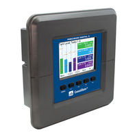
Precision Digital Corporation PD9000-GP-4AI Manual (27 pages)
Multivariable Controller
Brand:
Precision Digital Corporation
| Category:
Controller
| Size: 5 MB
Table of Contents
Main Screen
2
Channel Details Screen
2
Inputs and Outputs
3
Channel Settings
6
Alarm Settings
7
Inputs Settings
8
Outputs Settings
8
System Display Settings
9
Modbus Settings
9
Ma Analog Input Connections
11
Analog Output Connections
12
Digital Input Connections
12
Digital Output Connections
12
Specifications
14
Real Time Clock
15
Ma Analog Inputs
17
Pulse Inputs
17
Digital Inputs and Outputs
17
Modbus ® Serial Communications
18
Ethernet Communications
18
Consolidator+ Software
18
Overall Dimensions
19
Panel Mounting
20
Ordering Information
23
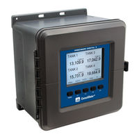
Precision Digital Corporation PD9000-GP-4AI Manual (17 pages)
Multivariable Controller
Brand:
Precision Digital Corporation
| Category:
Controller
| Size: 3 MB
Table of Contents
Main Screen
2
Channel Details Screen
2
Inputs and Outputs
3
Ma Analog Input Connections
6
Analog Output Connections
7
Digital Input Connections
7
Digital Output Connections
7
Specifications
9
Ma Analog Inputs
10
Pulse Inputs
10
Modbus ® Serial Communications
12
Ethernet Communications
12
Consolidator+ Software
12
Overall Dimensions
13
Ordering Information
14
Advertisement
Advertisement
Related Products
Precision Digital Corporation PD9000-GP-4AI-10RY
Precision Digital Corporation PD9000-GP-4AI-5AO-10RY
Precision Digital Corporation PD9000-GP-4AI-20RY
Precision Digital Corporation PD9000-GP-4AI-5AO-20RY
Precision Digital Corporation PD9000-GP-4AI-1ORY
Precision Digital Corporation PD9000-GP-4AI-5AQ-1ORY
Precision Digital Corporation PD9000-GP-4PI
Precision Digital Corporation PD9000-GP-4PI-5AO-10RY
Precision Digital Corporation PD9000-GP-4PI-4AI-5AO-10RY
Precision Digital Corporation PD9000-GP-4PI-4AI-5AQ
Precision Digital Corporation Categories
Measuring Instruments
Controller
Cash Counter
Scanner
Racks & Stands
More Precision Digital Corporation Manuals
Login
Sign In
OR
Sign in with Facebook
Sign in with Google
Upload manual
Upload from disk
Upload from URL