Sign In
Upload
Manuals
Brands
Powtran Manuals
Inverter
PI9000 series
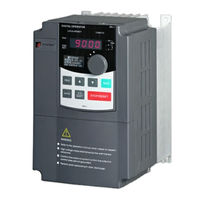
Powtran PI9000 series Frequency Inverter Manuals
Manuals and User Guides for Powtran PI9000 series Frequency Inverter. We have
2
Powtran PI9000 series Frequency Inverter manuals available for free PDF download: User Manual, Quick Manual
Powtran PI9000 series User Manual (256 pages)
Frequency Inverter
Brand:
Powtran
| Category:
Inverter
| Size: 5 MB
Table of Contents
Table of Contents
2
Chapter 1.Inspection And Safety Precautions
7
Foreword
7
Inspection after Unpacking
7
Instructions on Nameplate
7
Model Designation
7
Safety Precautions
8
Table of Contents
8
Precautions
11
Scope of Applications
12
Chapter 2 Standard Specifications
13
Technical Specifications
13
Standard Specifications
20
Appearance and Installation Holes Size
24
Dimensions
24
PI9100 Series
24
PI9200 Series
27
PI9300 Series
29
PI9400 Series
30
Keyboard Size Diagram
31
Chapter 3 Keyboard
33
Keyboard Description
33
Keyboard Indicators
33
Description of Operation Panel Keys
34
Examples of Parameter Settings
34
Instructions on Viewing and Modifying Function Code
34
Motor Parameter Auto Tunning
36
Password Settings
36
The Way to Read Parameters in Various Status
36
Chapter 4 Commissioning
38
Chapter 5 Function Parameter
40
Menu Grouping
40
D0 Group - Monitoring Function Group
41
Wobbulate, Fixed-Length and Counting:e0.00-E0.11
41
F0 Group - Basic Function Group
44
F1 Gruop - Input Terminals Group
47
F2 Group - Output Terminals Group
51
F3 Group - Start and Stop Control Group
53
F4 Group - V/F Control Parameters
55
F5 Group - Vector Control Parameters
56
F6 Group - Keyboard and Display
57
F7 Group - Auxiliary Function Group
59
F8 Group - Fault and Protection
63
F9 Group - Communication Parameter
69
FA Group - Torque Control Parameters
70
Fb Group - Control Optimization Parameters
71
E0 Group - Wobbulate, Fixed-Length and Counting
72
E1 Group - Multi-Stage Command, Simple PLC
73
E2 Group - PID Function
77
E3 Group – Virtual DI、Virtual DO
79
B0 Group - Motor Parameters
82
Y0 Group - Function Code Management
84
Y1 Group - Fault Query
86
Function Parameter Description
90
Basic Function Group: F0.00-F0.27
93
Input Terminals: F1.00-F1.46
103
Output Terminals: F2.00-F2.19
117
Start and Stop Control: F3.00-F3.15
122
V/F Control Parameters: F4.00-F4.14
126
Vector Control Parameters: F5.00-F5.15
130
Keyboard and Display: F6.00-F6.19
132
Auxiliary Function: F7.00-F7.54
137
Fault and Protection:f8.00-F8.35
146
Communications Parameters: F9.00-F9.07
154
Torque Control Parameters:fa.00-FA.07
156
Control Optimization Parameters: Fb.00-Fb.09
157
Extended Parameter:fc.00-FC.02
159
Multi-Stage Command, Simple PLC: E1.00-E1.51
162
PID Function: E2.00-E2.27
166
Virtual DI、Virtual DO:E3.00-E3.21
171
Motor Parameters: B0.00-B0.35
176
Function Code Management:y0.00-Y0.04
180
Fault Query:y1.00-Y1.30
183
Chapter 6 EMC (Electromagnetic Compatibility)
188
Definition
188
Electromagnetic Interference and Installation Precautions
188
EMC Directive
188
EMC Standard
188
Harmonic Effect
188
Electromagnetic Equipments
189
Equipments to the Inverter
189
Remedies for Leakage Current
189
Remedies for the Interferences from the Inverter to the Surrounding
189
Remedies for the Interferences from the Surrounding Electromagnetic
189
Precautions on Installing EMC Input Filter at the Input End of Power Supply
190
7.1 Fault Alarm and Countermeasures
191
Chapter 7 Troubleshooting
191
Chapter 8 Installation and Spare Circuit
197
Installation Direction and Space
197
Operating Environment
197
Wiring Diagram
197
Wiring Diagram(< 11Kw)
198
Wiring Diagram(11Kw to 15Kw)
199
Wiring Diagram(18.5Kw to 355Kw)
200
Main Circuit Terminal (G Type)
201
PI9000 Main Circuit Terminal
201
8-5-1. Description of Control Circuit Terminals
202
Control Circuit Terminals
202
Function Description of Main Circuit Terminal
202
Arrangement of Control Circuit Terminals
204
Spare Circuit
205
Chapter 9 Maintenance and Repair
206
Parts for Regular Replacement
207
Measuring and Readings
208
Chapter 10 Options
209
Options
210
Noise Filter
212
Output EMI Filter
213
Input Filter(690V)
214
Output Filter
215
Input AC Choke
216
Input AC Choke(690V)
219
Output AC Choke
220
Output AC Choke(690V)
222
DC Choke
224
Specifications of Circuit Breakers, Cables and Contactors
226
Chapter 11 Warranty
228
Appendix I RS485 Communication Protocol
229
I-2 Check Mode
233
I-3 Definition of Communication Parameter Address
235
Appendix II How to Use Universal Encoder Expansion Card
241
Appendix Ⅲ Description on Proportion Linkage Function
245
Appendix IV CAN Bus Communication Card Use Description
248
Appendix V Profibus-DP Communication Card Use Description
250
V-2-3.LED Indicator Functions
251
Warranty Card
252
Warranty Card
253
Advertisement
Powtran PI9000 series Quick Manual (52 pages)
Brand:
Powtran
| Category:
DC Drives
| Size: 2 MB
Table of Contents
Parameters Setting
9
Frequency Setting
19
Parameters Setting
23
Control Panel
29
Conveyor Belt
31
Inverter Setting
50
Advertisement
Related Products
Powtran PI9000-S Series
Powtran PI9100-0R7G1
Powtran PI9100-0R7G3
Powtran PI9200-022G3
Powtran PI9200-037F3
Powtran PI9400-075F3
Powtran PI9400-093F3
Powtran PI9200-093G3
Powtran PI9400-093G3
Powtran PI9400-132G3
Powtran Categories
Inverter
DC Drives
Controller
Circuit breakers
Servo Drives
More Powtran Manuals
Login
Sign In
OR
Sign in with Facebook
Sign in with Google
Upload manual
Upload from disk
Upload from URL