Advertisement
Quick Links
Download this manual
See also:
User Manual
Quick guide of PI9000 operation
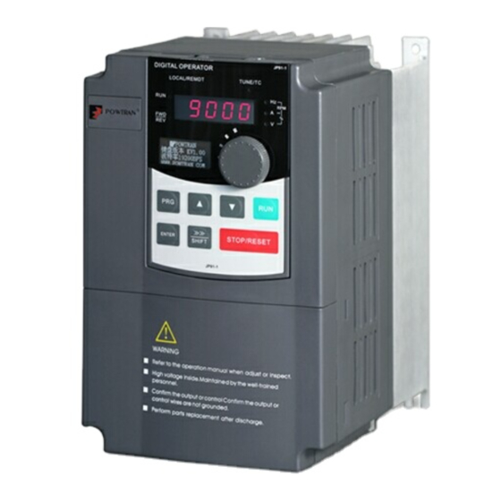
1.The introduction of new generation of PI9000
My future ,drive and control
2. The new generation of PI9000 has following feature .
3. Installation of PI9000 procedure :
4.Connection of peripheral devices.
5.Keyboard operating instruction.
6.Trial operation follow chart
7.Wiring Of PI9000 inverter
8.How to perform motor auto-turning
9. Apply the braking unit and braking resistor
10.1. Operate the VFD with keyboard
10.2 Operating Forward and reverse key of key board for JOG running
10.3.Operating VFD by I/O terminals board.
10.3.2. wiring of I/O interface terminal
10.3.3. FWD and REV running controlled by I/O terminal .
10.3.4. FWD and REV JOG running controlled by I/O terminal
10.3.5. three line control mode
11. Frequency setting with external potentiometer (Variable resistor)
12. Frequency setting by analog current (AI2)
13.Employ output analog signal for monitoring current ,frequency ,speed etc.
14. Multi-speed applying with I/O interface terminal
15.Frequency UP and Down controlled by I/O interface terminal board
16.1.Application of multi-function output .(1) alarm output
16.2.Application of multi-function output 2. ( frequency arrival and frequency detecting )
17. PID control for constant pressure water supply-electrical diagram ( 0-10V signal feedback )
18. PI9000 apply in air compressor retrofitting with PID control function.
19.Application of PI9000 series inverters in crane
20. Fault Diagnosis
Service center of POWTRAN technology company
Advertisement

Related Manuals for Powtran PI9000


Summary of Contents for Powtran PI9000
- Page 1 16.2.Application of multi-function output 2. ( frequency arrival and frequency detecting ) 17. PID control for constant pressure water supply-electrical diagram ( 0-10V signal feedback ) 18. PI9000 apply in air compressor retrofitting with PID control function. 19.Application of PI9000 series inverters in crane 20.
- Page 2 1.The introduction of new generation of PI9000 of POWTRAN Technology. My future ,drive and control The PI9000 series inverter is high-performance motor control module and consists of V/F, sensorless vector control (SVC) and torqure control. It is mainly responsible for high performance control and overall protection of the motor, controlling the motor through sending running commands to multiple channels or performing close loop vector control through encoder interface.
- Page 3 2. The new generation of PI9000 has following feature . My future ,drive and control Five digital two analog input signal, two analog output ,two high speed Input/output terminal port and one relay 0:V/Fz1:open loop flux vector control 2:open loop without sensor flux vector control...
- Page 4 3. Installation of PI9000 procedure : My future ,drive and control Install show picture -1 Service center of POWTRAN technology company...
- Page 5 My future ,drive and control Install show picture -2 Service center of POWTRAN technology company...
- Page 6 Power on inverter My future ,drive and control keyboard Front cover I/O control terminal Main Terminal cover Service center of POWTRAN technology company...
- Page 7 4.Examples of connections between the Inverter typical peripheral devices are shown. My future ,drive and control Please refer to “APPLICATION OF ”. OPTIONAL EQUIPMENT Service center of POWTRAN technology company...
- Page 8 2.Change the function code in the second menu 2.Also acts as the Reset key 3.Change the value of function code in the third menu 4.Frequency setting in the run or stop mode. when a fault has occurred. Service center of POWTRAN technology company...
-
Page 9: Parameters Setting
Press ENTER y0.01 flash 3. Parameters setting flash Press ENTER Press ENTER Press PRG Press UP 50.00 F0.00 F0.01 050.00 Press SHIFT Press DOWN Press PRG Press PRG Press ENTER 25.00 F0.02 25.00 50.00 flash Service center of POWTRAN technology company... - Page 10 6.Trial operation follow chart My future ,drive and control Frequency setting Trail (F0.03,F0.04,F0.07) PI9000 has a good vector operat control Performance . we suggestion you select Motor Startup mode Vector control mode . (F3.00) Control mode Selection (F0.00) Proper accel. and Decel.
- Page 11 7.Wiring My future ,drive and control Service center of POWTRAN technology company...
- Page 12 . Main terminal My future ,drive and control Main circuit terminal(<7.5KW, 380V): Input power Motor Supply reactor Braking resistor Main circuit terminal(11kW to 15kW, 380V): Input power Braking Motor Supply reactor resistor Service center of POWTRAN technology company...
- Page 13 The main terminal of 45~220kW(380V)inverter My future ,drive and control Power The main terminal of 18.5~355kW(380V)inverter Supply input Power Ground Motor To earth reactor supply Braking Unit Ground Motor ground To earth reactor Braking Unit Service center of POWTRAN technology company...
- Page 14 I/O control terminal of PI9000. My future ,drive and control There are two type of controller board of PI9000. The I/O terminal of 9KLCB controller board The I/O terminal of 9KSCB controller board Service center of POWTRAN technology company...
- Page 15 0.01 ~ F0.19 (maximum frequency ) b0.04 rated frequency 0 ~ 36000RPM b0.05 rated rotation speed b0.27 motor auto-turning 0:no operation selection 1,Asynchronous motor parameters still auto tunning. 2.Asynchronous motor parameters comprehensive auto tunning. Service center of POWTRAN technology company...
- Page 16 6. You can test whether the PG card is OK or not in the parameter d0.33 (ABZ position),Also you can monitor the encoder feedback speed in parameter d0.26. Motor basic Going to Auto-turning Auto-turning Parameter Finish auto-turning setting Service center of POWTRAN technology company...
- Page 17 0:no operation selection 1,Asynchronous motor parameters still auto tunning. 2.Asynchronous motor parameters comprehensive auto tunning. b0.29 1~65535 2500 PG Pulse b0.28 PG Type ABZ incremental encoder b0.34 PG Dropped Inspection 0.1S-10S Time Service center of POWTRAN technology company...
- Page 18 Torque ,if connect to braking unit ,it can provide maximum of 150% torque . It is no need to set any parameters for connecting the braking unit The braking function is activated in default ! The activated of DC braking Voltage is 130% U Service center of POWTRAN technology company...
-
Page 19: Frequency Setting
My future ,drive and control Change the Display content With SHIFT button F0.24=1 switchover FWD and REV Running direction Run command by key Stop motor board F0.11=0 , F0.11=0 Frequency setting F0.03=4 (keyboard in default) Service center of POWTRAN technology company... - Page 20 (DI3 )Input Terminal FWD JOG command Function Selection F1.03 (DI4) Input Terminal Function Selection REV JOG command F7.00 Jog running frequency 0.00~F0.19(Maximum frequency) 2.00Hz F7.01 Jog acceleration time 0.1~3600.0S 20.0S F7.02 Jog deceleration time 0.1~3600.0S 20.0S Service center of POWTRAN technology company...
- Page 21 (I/O) terminals for connecting pushbuttons, switches and other operator interface devices or control signals. For example: Operating this Button connecting to I/O interface for controlling the Inverter . Control cabinet Operate VFD by operating panel Service center of POWTRAN technology company...
- Page 22 10.3.2. wiring of I/O interface terminal . My future ,drive and control ~ 3A/250VAC 5A/30VDC +10V external potentiometer for giving 0-10V input signal Push button & potentiometer Service center of POWTRAN technology company...
-
Page 23: Parameters Setting
1:Terminal command channel (LED ON) F0.24 running direction 0: Consistent direction F1.00 DI1 function selection 1.Forward running direction F1.01 DI2 function selection 2.Reverse running direction F1.10 Terminal command mode 0.two line control mode 1 2.Parameters setting Service center of POWTRAN technology company... - Page 24 1:Terminal command channel (LED ON) F1.00 DI1 function selection 1.Forward running direction F1.01 DI2 function selection 2.Reverse running direction F1.02 DI3 function selection 3:Three wire mode running control F1.10 Terminal command mode 2. three line control mode 1 Service center of POWTRAN technology company...
- Page 25 F0.11 command source selection 1:Terminal command channel (LED ON) F0.03 frequency setting source selection 2:AI1 analog signal input F1.00 DI1 function selection 1.Forward running direction F1.10 Terminal command mode 0.Two line control mode 1 Service center of POWTRAN technology company...
- Page 26 F0.11 command source selection 1:Terminal command channel (LED ON) F0.03 frequency setting source selection 2:AI2 analog signal input F1.00 DI1 function selection 1.Forward running direction F1.11 Terminal command mode 1.two line control mode 2 Service center of POWTRAN technology company...
- Page 27 F2.17 -10.00~+10.00 DA1 gain 1.00 Can also be used for self- definition analog output c F2.18 DA2 Zero bias coefficient -100.0%~+100.0% 0.00% urve.deviationdeviation F2.19 -10.00~+10.00 DA2 gain 1.00 Service center of POWTRAN technology company...
- Page 28 MS speed terminal 1 F1.05 DI6 function selection Ms speed terminal 2 DI7 function selection Ms speed terminal 3 F1.06 E1.01 MS speed 1 -100.0~100.0% E1.02 MS speed 2 -100.0~100.0% E1.04 MS speed 3 -100.0~100.0% Service center of POWTRAN technology company...
-
Page 29: Control Panel
DI3 function selection Three-wire operation control F1.03 DI4 function selection 9:frequency UP by terminal (UF) F1.04 DI5 function selection 10:frequency Down by terminal (DN) F1.11 change rate of terminal up and down 0.01~100.00Hz/s 1.0Hz Service center of POWTRAN technology company... - Page 30 DI1 function selection Forward rotation F1.03 DI4 function selection Fault reset 0: No output 1:motorforward running 2.Fault output 3:Frequency level detection FDT output 4:Frequency arrival 5:in Zero speed F2.02 Relay output selection operation .6~40:Reserved Service center of POWTRAN technology company...
-
Page 31: Conveyor Belt
1:Terminal command channel (LED ON) F1.00 DI1 function selection Forward rotation F2.02 Relay output selection 4:Frequency level detection FDT output F7.23 (FDT) frequency detection value 0.00~U0.10(Maximum frequency ) 35Hz F7.24 FDT detection hysteresis 0.0%~100.0%(FDT level ) Service center of POWTRAN technology company... - Page 32 Pressure all the time . E2.01 should be set to1.2/2.0x100% =60% Feedback signal from pressure transmitter negative action, when Δ>0 is positive, frequency rises and when Δ<0 is negative, frequency falls. For constant Pressure water supply. Service center of POWTRAN technology company...
- Page 33 0.25s dormancy frequency(F7.48)to maximum F7.46 Awakens frequency frequency (F0.19) 0.00Hz F7.47 Awakens delay time 0.0s to 6500.0s 0.0s F7.48 Dormancy frequency 0.00Hz to awakens frequency(F7.46) 0.00Hz F7.49 Dormancy delay time 0.0s to 6500.0s 0.0s Service center of POWTRAN technology company...
- Page 34 -electrical diagram ( 0-20mA signal feedback ) My future ,drive and control Pressure transmitter 0-20mA analog output signal negative action, when Δ>0 is positive, frequency rises and when Δ<0 is negative, frequency falls. For constant Pressure water supply. Service center of POWTRAN technology company...
- Page 35 0.25s dormancy frequency(F7.48)to maximum F7.46 Awakens frequency frequency (F0.19) 0.00Hz F7.47 Awakens delay time 0.0s to 6500.0s 0.0s F7.48 Dormancy frequency 0.00Hz to awakens frequency(F7.46) 0.00Hz F7.49 Dormancy delay time 0.0s to 6500.0s 0.0s Service center of POWTRAN technology company...
- Page 36 ,please set Kp a little small ,or set Ti a little big ,if the system need to air restore soon after air leaking ,please set Kp a little big ,or set the Ti a little small . Service center of POWTRAN technology company...
- Page 37 18. PI9000 apply in air compressor retrofitting with PID control function. My future ,drive and control The air compressor variable frequency control system is mainly composed of a frequency converter, a pressure sensor (pressure transmitter ). A pressure sensor component is first used to test the pressure in the reservoir .
- Page 38 Wirings of electrical diagram with 0-20mA type of pressure transmitter My future ,drive and control Pressure transmitter is installed On the pipeline of the air reservoir It will sent analog signal 0-20mA to inverter . Service center of POWTRAN technology company...
- Page 39 Wirings of electrical diagram with 0-10V type pressure transmitter My future ,drive and control Service center of POWTRAN technology company...
- Page 40 E2.11 PID feedback missing detection value 0.1%-100% 0.0% E2.12 PID feedback missing detection time 0.0S-20S F1.00 DI1 function selection 1.Forward running direction F1.03 DI4 function selection 9:fault reset F1.02 DI3 function selection 22.PID pause Service center of POWTRAN technology company...
- Page 41 19.Application of PI9000 series inverters in crane My future ,drive and control PI9000 series has good vector control Performance can run At 4 four quadrant operation . It can be apply crane Lift and hoisting machine and elevator .etc middle speed...
- Page 42 We can select the DC brake function before running to hold the Motor for prolong the working life of mechanical of brake . Also can using the DC braking function before stop to protecting From load loss suddenly . U6 parameter group Service center of POWTRAN technology company...
- Page 43 4. It will display „END” in the menu at the end of auto-turning .it means the auto Turning has performed successfully . CODEb Description of Code Range of setting rated power 15.000 rated frequency 50Hz rated rotation speed 1450 rated voltage 380V rated current motor auto-turning selection 2:complete Rotational auto-tuning Service center of POWTRAN technology company...
- Page 44 DC brake keep time 0.0~50.s 1.0s F3.03 DC brake beginning frequency at stop 0.00~F01.07 F3.06 Dc brake time 0.0~50.s E1.01 MS speed 1 -100.0~100.0% E1.02 MS speed 2 -100.0~100.0% E1.04 MS speed 4 -100.0~100.0% Service center of POWTRAN technology company...
- Page 45 20. Fault Diagnosis My future ,drive and control PI9000 inverter has a number of warning information and protection function. In case of abnormal fault, the protection function will be invoked, the inverter will stop output, and the faulty relay contact of the inverter will start, and the fault code will be displayed on the display panel of the inverter.
- Page 46 "Inquiry/Command"of master. Here, the master refers to a Personnel Computer(PC), an industrial control device or a programmable logic controller (PLC), etc. and the slave refers to PI9000 inverter. Master can communicate with individual slave, also send broadcasting information to all the lower slaves. For the single "Inquiry/Command"of master, slave will return a signal(that is a response) to master;...
- Page 47 My future ,drive and control Communication data structure PI9000 series inverter's Modbus protocol communication data format is as follows: in RTU mode, messages are sent at a silent interval of at least 3.5 characters. There are diverse character intervals under network baud rate, which is easiest implemented (as shown in Figure T1-T2-T3-T4).
- Page 48 My future ,drive and control Service center of POWTRAN technology company...
- Page 49 1.Soft setting: PC com port com1,inverter Baud rate 9600, Data format, My future ,drive and control no parity: data format <8, N, 2> Service center of POWTRAN technology company...
-
Page 50: Inverter Setting
F9.04 Communication 0.0S F9.05 Communication F9.06 Communication read 4. Command code: 03H , reads N words (max.12 words), for example: for the inverter with slave address 01, its start address F0.02 continuously reads two values. Service center of POWTRAN technology company... - Page 51 My future ,drive and control Service center of POWTRAN technology company...
- Page 52 5. Command Code: 06H, write a word. For example: Write My future ,drive and control 5000(1388H) into the address F00AH of the inverter with slave address 02H. Service center of POWTRAN technology company...
Need help?
Do you have a question about the PI9000 and is the answer not in the manual?
Questions and answers