Sign In
Upload
Manuals
Brands
Perkins Manuals
Engine
M190C
Perkins M190C Manuals
Manuals and User Guides for Perkins M190C. We have
4
Perkins M190C manuals available for free PDF download: Troubleshooting Manual, Installation Manual, User Handbook Manual
Perkins M190C Troubleshooting Manual (220 pages)
Brand:
Perkins
| Category:
Engine
| Size: 1.91 MB
Table of Contents
Important Safety Information
2
Table of Contents
3
Troubleshooting Section
5
Electronic Troubleshooting
5
System Overview
5
Glossary
8
Electronic Service Tools
12
Indicator Lamps
14
Replacing the ECM
17
Self-Diagnostics
18
Sensors and Electrical Connectors
19
Engine Wiring Information
23
ECM Harness Connector Terminals
28
Programming Parameters
30
Test ECM Mode
30
Factory Passwords
30
Flash Programming
31
Injector Trim File
31
Customer Specified Parameters
33
Customer Specified Parameters Table
35
Customer Specified Parameters Worksheet
36
System Configuration Parameters
37
Troubleshooting Without a Diagnostic Code
38
Alternator Noise
38
Alternator will Not Charge
38
Battery
39
Can Not Reach Top Engine RPM
39
Coolant in Engine Oil
40
Coolant Temperature Is too High
41
ECM will Not Accept Factory Passwords
42
ECM will Not Communicate with Other Systems or Display Modules
42
Electronic Service Tool will Not Communicate with ECM
43
Engine Cranks but will Not Start
44
Engine Has Early Wear
47
Engine Misfires, Runs Rough or Is Unstable
48
Engine Oil in Cooling System
49
Engine Speed Does Not Change
50
Engine Stalls at Low RPM
50
Engine Vibration
51
Engine will Not Crank
52
Excessive Black Smoke
53
Excessive Engine Oil Consumption
54
Excessive Fuel Consumption
55
Excessive Valve Lash
57
Excessive White Smoke
58
Exhaust Temperature Is High
59
Fuel Dilution of Engine Oil
59
Intermittent Engine Shutdown
59
Intermittent Low Power or Power Cutout
60
Low Engine Oil Pressure
62
Low Power/Poor or no Response to Throttle
63
Mechanical Noise (Knock) in Engine
65
Noise Coming from Cylinder
65
Poor Acceleration or Response
66
Transmission Oil Pressure Is High
67
Transmission Oil Temperature Is High
68
Troubleshooting with a Diagnostic Code
69
Flash Codes
69
Diagnostic Codes
69
Diagnostic Code Cross Reference
71
No Diagnostic Codes Detected
73
CID 0001 Fmi 02
74
CID 0001 Fmi 05
74
CID 0001 Fmi 06
75
CID 0001 Fmi 07
75
CID 0002 Fmi 02
75
CID 0002 Fmi 05
76
CID 0002 Fmi 06
76
CID 0002 Fmi 07
77
CID 0003 Fmi 02
77
CID 0003 Fmi 05
77
CID 0003 Fmi 06
78
CID 0003 Fmi 07
78
CID 0004 Fmi 02
79
CID 0004 Fmi 05
79
CID 0004 Fmi 06
80
CID 0004 Fmi 07
80
CID 0005 Fmi 02
80
CID 0005 Fmi 05
81
CID 0005 Fmi 06
81
CID 0005 Fmi 07
82
CID 0006 Fmi 02
82
CID 0006 Fmi 05
83
CID 0006 Fmi 06
83
CID 0006 Fmi 07
84
CID 0041 Fmi 03
84
CID 0041 Fmi 04
84
CID 0091 Fmi 08
85
CID 0091 Fmi 13
85
CID 0094 Fmi 03
85
CID 0094 Fmi 04
85
CID 0096 Fmi 03
86
CID 0096 Fmi 04
86
CID 0100 Fmi 03
86
CID 0100 Fmi 04
87
CID 0100 Fmi 10
87
CID 0110 Fmi 03
87
CID 0110 Fmi 04
88
CID 0127 Fmi 03
88
CID 0127 Fmi 04
88
CID 0168 Fmi 00
89
CID 0168 Fmi 01
89
CID 0168 Fmi 02
89
CID 0172 Fmi 03
90
CID 0172 Fmi 04
90
CID 0174 Fmi 03
91
CID 0174 Fmi 04
91
CID 0177 Fmi 03
91
CID 0177 Fmi 04
91
CID 0190 Fmi 08
92
CID 0253 Fmi 02
92
CID 0261 Fmi 11
92
CID 0262 Fmi 03
93
CID 0262 Fmi 04
93
CID 0268 Fmi 02
93
CID 0342 Fmi 08
94
CID 0342 Fmi 11
94
CID 0526 Fmi 05
94
CID 0526 Fmi 06
95
CID 0526 Fmi 07
95
CID 0535 Fmi 03
96
CID 0535 Fmi 04
96
CID 0774 Fmi 08
96
CID 0774 Fmi 13
97
CID 1779 Fmi 05
97
CID 1779 Fmi 06
97
CID 1785 Fmi 03
98
CID 1785 Fmi 04
98
CID 1785 Fmi 10
98
CID 1797 Fmi 03
99
CID 1797 Fmi 04
99
CID 1834 Fmi 02
100
CID 2246 Fmi 05
100
CID 2246 Fmi 06
100
Troubleshooting with an Event Code
102
Event Codes
102
E096 High Fuel Pressure
104
E113 High Transmission Oil Pressure
104
E119 Low Fuel Level
105
E179 Alternator Not Charging
105
E194 High Exhaust Temperature
105
E198 Low Fuel Pressure
106
E232 High Fuel/Water Separator Water Level
106
E268 Unexpected Engine Shutdown
107
E360 Low Engine Oil Pressure
107
E361 High Engine Coolant Temperature
108
E362 Engine Overspeed
109
E363 High Fuel Supply Temperature
109
E396 High Fuel Rail Pressure
110
E398 Low Fuel Rail Pressure
110
E539 High Intake Manifold Air Temperature
111
E877 High Transmission Oil Temperature
112
E1044 High Intake Manifold Pressure
112
E1045 Low Intake Manifold Pressure
112
E2143 Low Engine Coolant Level
113
Diagnostic Functional Tests
115
Volt Sensor Supply Circuit - Test
115
CAN Data Link Circuit - Test
122
Coolant Level Sensor Circuit - Test
126
Data Link Circuit - Test
131
ECM Memory - Test
137
Electrical Connectors - Inspect
138
Electrical Power Supply Circuit - Test
142
Engine Pressure Sensor Open or Short Circuit - Test
146
Engine Speed/Timing Sensor Circuit - Test
154
Engine Temperature Sensor Open or Short Circuit - Test
159
Engine Temperature Sensor Open or Short Circuit - Test
165
Fuel Level - Test
170
Fuel Rail Pump Solenoid - Test
173
Ignition Keyswitch Circuit and Battery Supply Circuit - Test
177
Indicator Lamp Circuit - Test
183
Injector Data Incorrect - Test
186
Injector Solenoid Circuit - Test
188
Speed Control (PWM) - Test
196
Starting Aid (Glow Plug) Relay Circuit - Test
201
Switch Circuits - Test
205
Throttle Position Sensor - Test
207
Transmission Oil Temperature - Test
209
Wastegate Solenoid - Test
212
Index
218
Advertisement
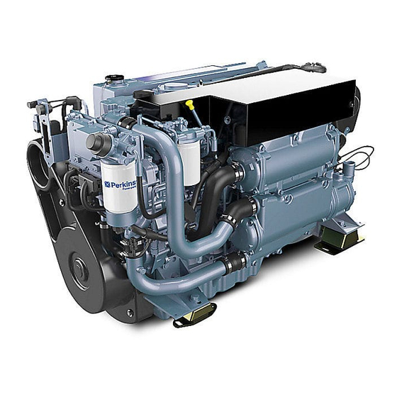
Perkins M190C Installation Manual (88 pages)
6 cylinder, turbocharged, intercooled, diesel engine for marine propulsion applications
Brand:
Perkins
| Category:
Engine
| Size: 7.83 MB
Table of Contents
General Safety Precautions
5
Table of Contents
7
1 Location of Engine Installation Points
11
2 Engine Mounting
13
Installation Angles
13
Nose down Capability
13
Engine Mounting Brackets
14
Flexible Engine Mounts
15
Engine Bearers
16
3 Propeller Shafts and Couplings
17
Propeller Shafts
17
4 Exhaust Systems
19
Wet Systems
19
Dry Systems
21
Part Dry, Part Wet Systems
22
Water Lift Systems
22
Silencers
23
5 Engine Room Ventilation
25
6 Engine Cooling Systems
27
Auxiliary Water Systems
27
Keel Cooling System
28
7 Fuel Systems
29
Cleanliness of Fuel System Components
29
Cleanliness of the Engine
29
Environment
29
New Components
29
Refuelling
29
Fuel Connections
29
Thread Details of the Connections on the Engines for Fuel Pipes
30
Typical Fuel Systems
31
Alarm Tank
32
8 Engine Electrical Systems
33
Engine Wiring Looms
33
Breakers
34
Interconnecting Cables
35
Instrument Panels
36
Main Panel
36
Auxiliary Panel
37
Mini Marine Power Display (MMPD) Digital Panel
38
Keyswitch Panel
38
Throttle Synchronization / Slow Vessel Mode Panel
39
Possible Panel Configurations
40
Mini Marine Power Display (MMPD) Instructions
41
CAN Data Link
45
For Engines Without an MJB (Marine Junction Box)
46
For Engines Fitted with the Marine Junction Box (MJB)
47
Single Engine MJB Features and Mounting Details
48
Twin Engine MJB Features and Mounting Details
49
Power Connections
50
Current Requirements 12 or 24 VDC System
50
ECM Port or Starboard Interface Connectors
50
Grounding the Battery Negative
50
Port or Starboard Expansion Connectors
51
Diagnostic Lamp (Pin 2)
52
Warning Lamp (Pin 1)
52
Battery (Pin 11)
52
Keyswitch (Pin 12)
52
Maintenance Clear Switch (Pin 16)
52
Cold Start System
53
Cold Start Data 12V and 24V
53
Battery Performance
53
Battery to Starter Lead Resistance
53
Battery Isolator Switches
54
Zinc Anode Bonding System
54
Typical System in Common Use
55
Optional Sensors
55
Wiring Diagrams
57
Engine Wiring Harness Overview, Without MJB
57
Engine Wiring Harness, Wiring Description, Without MJB
58
Engine Wiring Harness Overview
59
Panel Harness Overview
60
Engine Wiring Harness 1
61
Engine Wiring Harness 2
62
Engine Panels 1
63
Interconnecting Leads 1
64
Master/Slave Option, Port
65
Marine Junction Box
66
Master/Slave Option, Starboard
67
Interconnecting Leads 2
68
Engine Panels 2
69
9 Engine Controls
71
10 Provision for Power Take-Off
73
For Axial Drives
73
For Belt Drives
73
Polar Diagram
74
11 Calorifier and Block Heater Connections
75
Calorifier
75
Block Heater Connection Points
75
12 Options
77
Gearbox Oil Temperature Sensor
77
13 Reference Data
79
Basic Data M300C M250C M216C M190C
79
Cooling
79
Fuel System
80
Air Intake
80
Lubricating System
81
Electrical System
81
Cold Start Limits
81
Perkins M190C Installation Manual (82 pages)
Brand:
Perkins
| Category:
Engine
| Size: 8.23 MB
Table of Contents
Table of Contents
7
1 Location of Engine Installation Points
11
2 Engine Mounting
13
Installation Angles
13
Nose down Capability
13
Engine Mounting Brackets
14
Flexible Engine Mounts
15
Engine Bearers
16
3 Propeller Shafts and Couplings
17
Propeller Shafts
17
4 Exhaust Systems
19
Wet Systems
19
Dry Systems
21
Part Dry, Part Wet Systems
22
Water Lift Systems
22
Silencers
23
5 Engine Room Ventilation
25
6 Engine Cooling Systems
27
Auxiliary Water Systems
27
Keel Cooling System
28
7 Fuel Systems
29
Cleanliness of Fuel System Components
29
Cleanliness of the Engine
29
Environment
29
New Components
29
Refuelling
29
Fuel Connections
29
Thread Details of the Connections on the Engines for Fuel Pipes
30
Typical Fuel Systems
31
8 Engine Electrical Systems
33
Engine Wiring Looms
33
Breakers
34
Interconnecting Cables
35
Instrument Panels
36
Main Panel
36
Auxiliary Panel
37
Mini Marine Power Display (MMPD) Digital Panel
38
Keyswitch Panel
39
Possible Panel Configurations
40
Mini Marine Power Dispaly (MMPD) Instructions
41
CAN Data Link
45
Marine Junction Box (MJB)
46
Single Engine MJB Features and Mounting Details
47
Twin Engine MJB Features and Mounting Details
48
Power Connections
49
Current Requirements 12 or 24 VDC System
49
ECM Port or Starboard Interface Connectors
49
Grounding the Battery Negative
49
Port or Starboard Expansion Connectors
50
Diagnostic Lamp (Pin 2)
51
Warning Lamp (Pin 1)
51
Battery (Pin 11)
51
Keyswitch (Pin 12)
51
Maintenance Clear Switch (Pin 16)
51
Cold Start System
52
Cold Start Data 12V and 24V
52
Battery Performance
52
Battery to Starter Lead Resistance
52
Battery Isolator Switches
53
Zinc Anode Bonding System
53
Typical System in Common Use
54
Optional Sensors
54
Engine Wiring Harness Overview
55
Panel Harness Overview
56
Wiring Diagrams
57
Engine Wiring Harness 1
57
Engine Wiring Harness 2
58
Engine Panels 1
59
Interconnecting Leads 1
60
Master/Slave Option, Port
61
Marine Junction Box
62
Master/Slave Option, Starboard
63
Interconnecting Leads 2
64
Engine Panels 2
65
9 Engine Controls
67
10 Provision for Power Take-Off
69
For Axial Drives
69
For Belt Drives
69
Polar Diagram
70
11 Calorifier and Block Heater Connections
71
Calorifier
71
Block Heater Connection Points
71
12 Reference Data
73
Basic Data M300C/M250C
73
Cooling
73
Fuel System
74
Air Intake
74
Lubricating System
75
Electrical System
75
Cold Start Limits
75
Basic Data M216C/M190C
77
Cooling
77
Fuel System
78
Air Intake
78
Lubricating System
79
Electrical System
79
Cold Start Limits
79
Advertisement
Perkins M190C User Handbook Manual (64 pages)
6 cylinder, turbocharged, intercooled, diesel engines for marine propulsion applications
Brand:
Perkins
| Category:
Engine
| Size: 3.68 MB
Table of Contents
General Safety Precautions
5
Table of Contents
7
1 Engine Views
11
Introduction
11
Location of Engine Parts
12
Front and Right Side View
12
Rear and Left Side View
14
2 General Information
15
Introduction
15
Safety Notices
15
How to Care for Your Engine
16
Engine Guarantee
17
Engine Identification
17
Contact Details
18
3 Operation Instructions
19
Running-In
19
Control Panel Overview
20
Auxiliary Control Panel Overview
21
Digital Control Panel Overview
22
Keyswitch Panel Overview
23
Throttle Synchronization and Slow Vessel Mode Panel
23
Slow Vessel Mode Operation
23
Preparations for an Engine Start
24
How to Start the Engine
25
How to Stop the Engine
26
Adjustment of the Engine Speed Range
26
Operational Angles
26
Nose down Capability
26
Circuit Breakers
27
4 Engine Fluids
29
Fuel Specification
29
Low Temperature Fuels
29
Lubricating Oil Specification
30
Coolant Specification
31
5 Regular Maintenance
33
Maintenance Periods
33
Schedules
34
When Required
34
Daily
34
Every Week
34
Initial 500 Service Hours
34
Every 500 Service Hours or 1 Year
34
Every 1000 Service Hours
35
Every 2000 Service Hours
35
Every 3000 Service Hours or 2 Years
35
Every 3000 Service Hours or 3 Years
35
Every 4000 Service Hours
35
Every 6000 Service Hours or 3 Years
35
How to Fill the Coolant Circuit
36
How to Drain the Coolant Circuit
37
Engines Fitted with Keel Coolers
37
How to Check the Specific Gravity of the Coolant
38
How to Drain the Auxiliary Water System
39
How to Check the Impeller of the Auxiliary Water Pump
40
How to Check the Drive Belt of the Alternator
41
How to Adjust the Belt Tension
42
How to Check the Condition of the Heat Exchanger
43
Cleaning the Heat Exchanger
43
If Tubestack Is Greasy
44
Tubestack Is Not Greasy
44
How to Renew the Element on the Primary Fuel Filter
45
How to Renew the Element on the Secondary Fuel Filter
47
How to Renew the Lubricating Oil of the Engine
48
How to Renew the Canister of the Lubricating Oil Filter
49
How to Renew the Engine Breather
50
How to Clean the Air Filter
51
How to Check the Condition of the Vibration Damper
52
How to Check the Valve Tip Clearances
53
TC Compression Stroke
53
TC Exhaust Stroke
54
Corrosion
55
Supplementary Tools
55
6 Engine Preservation
57
Introduction
57
Procedure
57
How to Add Antifreeze to the Auxiliary Water System for Engine Preservation Purposes
58
7 Parts and Service
59
Introduction
59
Service Literature
59
Training
59
General Data
61
Advertisement
Related Products
Perkins M115T
Perkins M135: M130C
Perkins M185C
Perkins Perama M25
Perkins Perama M30
Perkins M65
Perkins M265TI
Perkins M300TI
Perkins M300C
Perkins M216C
Perkins Categories
Engine
Lifting Systems
Microphone
Compact Loader
Inverter
More Perkins Manuals
Login
Sign In
OR
Sign in with Facebook
Sign in with Google
Upload manual
Upload from disk
Upload from URL