Sign In
Upload
Manuals
Brands
Parker Manuals
Controller
890CD
Parker 890CD Variable Frequency Drives Manuals
Manuals and User Guides for Parker 890CD Variable Frequency Drives. We have
4
Parker 890CD Variable Frequency Drives manuals available for free PDF download: Product Manual, Quick Start Manual
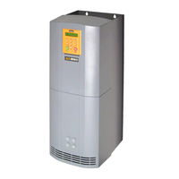
Parker 890CD Product Manual (710 pages)
Frequency, Frame E & F with STO SIL3/PLe
Brand:
Parker
| Category:
Controller
| Size: 7 MB
Table of Contents
Chapter 12 Routine Maintenance and Repair
6
Table of Contents
9
Chapter 1 Safety
11
Chapter 2 Getting Started
11
About this Manual
12
Equipment Inspection
14
Packaging and Lifting Details
14
Chapter 3 Product Overview
15
Product Range
16
Functional Diagrams
19
Keypads
21
Option Cards
22
Chapter 4 890CS & 890CD Common Bus Units
23
Step 1: Mechanical Installation
24
Step 2: Connecting Power
37
Step 3: Control Connections
49
Step 4: Checking the System
62
Powering-Up the System
66
Configure the 890CD Common Bus Drive
69
Initial Start-Up Routines
86
Chapter 5 890SD Standalone Drive
89
Step 1: Mechanical Installation
90
Step 2: Connecting Power
100
Step 3: Control Connections
109
Step 4: Powering-Up the Unit
119
Step 5: Run the Motor
134
Chapter 6 Safe Torque off
142
General Information
143
STO Function Description
144
Alignment to European Standards
145
Safety Specification
148
User Connections
149
STO Input Timing Diagrams
155
STO State Transition Diagram
160
STO Trip Annunciation
161
Safety Warnings and Limitations
162
Example User Wiring
165
STO Function Checking
173
Comprehensive Check
174
Regular Check
180
Chapter 7 Associated Equipment
183
Main Points
184
890CS : AC Line Reactors
185
External Braking Resistors
187
Dynamic Brake Resistor Overload Protection
192
890CS Semiconductor Protection Fuses
194
890CD Semiconductor Protection Fuses
195
Circuit Breakers
196
Filters
197
Chapter 8 Operating the Drive
201
Control Philosophy
202
Start/Stop and Speed Control
203
Starting and Stopping Methods
208
Application Advice
218
Chapter 9 The Keypad
249
Introduction
250
Keypad
250
Keypad
257
Contents
279
Remote Mounting the Keypad
289
Chapter 10 Keypad Menus
293
890CS Common Bus Supply
294
890 Common Bus/890 Standalone Drive
295
Chapter 11 Trips and Fault Finding
323
Trips
324
Fault Finding
347
Routine Maintenance and Repair
349
Routine Maintenance
350
Repair
350
Appendix A Options
352
Option Cards
353
Appendix B Sequencing Logic
355
Principle State Machine
356
External Control of the Drive
362
Appendix C Certification
369
What Is the EMC Directive?(2004/108/EC
370
Definition of Working Environments
372
General Installation EMC Considerations
373
Emissions
375
European Directives and the CE Mark
384
Appendix D Programming
388
Programming with Block Diagrams
389
Modifying a Block Diagram
390
Function Block Descriptions
391
Parameter Specifications
577
Parameter Table: PREF Number Order
579
Product Related Default Values
649
Appendix E Technical Specifications
650
Understanding the Product Code
651
Advertisement
Parker 890CD Product Manual (479 pages)
Brand:
Parker
| Category:
Controller
| Size: 3 MB
Table of Contents
Intended Users
4
Installation Details
4
Application Area
4
Chapter 1 Safety
4
Application Risk
7
Risk Assessment
7
Getting Started
9
About this Manual
10
How the Manual Is Organised
10
Installation
10
Initial Steps
11
Equipment Inspection
12
Packaging and Lifting Details
12
Product Overview
13
Product Range
14
890CD Common Bus Drive
15
Functional Diagrams
17
Option Cards
20
Control Board Access
20
Sizing the Enclosure
23
Enclosure/Environmental Information
24
Operation
26
Panel Mount Fixings
28
DIN Rail Mounting
28
Shield Bonding Clips
28
Installation Kit
29
Step 2: Connecting Power
30
Solid-State Short-Circuit Protection
30
Wiring Diagram
32
Key to Wiring Diagram
33
Power Connections - 890CS Common Bus Supply
35
Motor Thermistor
39
Busbar Installation
41
Step 3: Control Connections
42
Main Points 1
42
Control Connection Diagram
43
890CD Minimum Control Connections
44
Control Connections - 890CS Common Bus Supply
45
Control Connections - 890CD Common Bus Drive
47
Pre-Operation Checks
53
Initial Power-Up Conditions
55
Using the Keypad
57
How to Edit a Parameter
57
Speed Demand
58
Step 5: Run the Motor
59
Main Points
59
Before Applying Power
61
Powering-Up the Units
62
Initial Start-Up Routines
63
Routine 1: Local Mode
63
Routine 2: Remote Mode
65
890SD Standalone Drive
67
Step 1: Mechanical Installation
68
Fit the 890 Installation Kit to the Bottom of the Drive. 6
69
En61800
70
Mounting Dimensions
73
Key to Wiring Diagram
78
Main Points
85
890SD Minimum Control Connections
87
Control Connections - 890SD Standalone Drive
88
Step 4: Checking the System
94
Initial Power-Up Conditions
96
Using the DSE 890 Configuration Tool
97
Setup Parameters
99
Powering up the Unit
102
Associated Equipment
107
890CS : AC Line Reactors
109
External Braking Resistors
111
Wiring Details
112
890CS Dynamic Braking Resistor Kits - Usa/Canada
114
890SD Resistor Selection
116
Dynamic Brake Resistor Overload Protection
119
European Resistors
120
Circuit Breakers
122
Mechanical Brake
124
Operating the Drive
125
Control Philosophy
126
Start/Stop and Speed Control
127
Initial Power-Up Conditions
131
Control Key Definitions
132
Example: to View the INPUT CURRENT Diagnostic
132
Display Indications
133
The Menu System
134
Drive Status Indications
135
Alert Message Displays
135
Selecting Local or Remote Mode
136
LED Indications
140
Local to Remote Mode
143
The Menu System Map
148
How to Change a Parameter Value
152
How to Save the Application
153
Special Menu Features
154
Resetting to Factory Defaults (2-Button Reset)
154
Selecting the Menu Level
154
Power-Up Key Combinations
155
Changing the Product Code (3-Button Reset)
156
Restore Defaults
158
Control Key Definitions
160
Keys for Programming the Drive
160
Keys for Operating the Drive Locally
161
The PROG Key
163
Navigating the Menu System
168
Remote to Local Mode
170
Quick Tag Information
175
Password Protection (6901 Keypad)
176
To De-Activate Password Protection
177
To Re-Activate Password Protection
177
To Remove Password Protection (Default Status)
177
Remote Mounting the Keypad
182
Fitting the Remote 6901 Keypad
182
Assembly Procedure
183
Fitting the Remote 6511 Keypad
184
Keypad Menus
187
890CS Common Bus Supply
188
The DIAGNOSTIC Menu
188
The OPERATOR Menu
193
The QUICK SETUP Menu
205
Control Mode
206
Quick Setup Menu
206
Run Stop Mode
207
User Defined
208
Motor Current
209
Current Limit
210
Motor Base
210
The Setup Menu
215
The System Menu
215
Trips and Fault Finding
217
What Happens When a Trip Occurs
218
Drive Indications
218
Keypad Indications (When Connected)
218
Resetting a Trip Condition
219
Local Mode
219
Remote Mode
219
Trips Table
220
VDC Ripple
225
Hexadecimal Representation of Trips
234
Automatic Trip Reset (6901 Keypad)
234
Setting Trip Conditions (6901 Keypad)
235
Viewing Trip Conditions (6901 Keypad)
235
Viewing Trip Conditions (6511 Keypad)
235
Alert Messages
236
Control Board STATUS LED Indications
243
Routine Maintenance and Repair
245
Saving Your Application Data
246
Returning the Unit to Parker SSD Drives
246
Removing the Control Board
251
Sequencing Logic
253
Principle State Machine
254
Main Sequencing States
254
Function Block
255
Transition of States
256
S Tate Diagram
259
External Control of the Drive
260
Communications Command
260
Quick Stop
262
Enable Operation
262
Example Commands
263
Communications Status
264
Operation Enabled
265
Setpoint Reached
266
Internal Limit Active
266
Definition of Working Environments
271
General Installation EMC Considerations
272
Earthing Requirements
272
Cabling Requirements
273
Planning Cable Runs
273
Increasing Motor Cable Length
273
Relationship between Standards
275
En61000-6
275
Reducing Radiated Emissions
276
Conducted Emission
278
Star Point Earthing
279
Safety 8
279
Sensitive Equipment
280
Single VSD - Multiple Motors
281
European Directives and the CE Mark
281
CE Marking for Low Voltage Directive
281
Legal Requirements for CE Marking
282
Parker SSD Drives Responsibility
282
Customer Responsibility
282
Programming with Block Diagrams
286
Modifying a Block Diagram
287
Programming Rules
287
Saving Your Modifications
287
Understanding the Function Block Description
288
Function Blocks Alphabetically
289
Access Control
291
Analog Input
292
Break Enable
292
Break Value
292
Functional Description
293
Analog Output
294
Auto Restart
295
Comms Control
297
Comms Port
299
Digital Input
300
Digital Output
301
Drive Config
302
Drive Name
302
Dynamic Braking
310
Emc Capacitors
312
Reasons for Isolation
312
Firewire Ref
322
Local Control
330
Power up Mode
331
Mot Polarisation
335
To Start the STANDARD Polarisation
338
Phase Offset
345
Max Torque
350
Functional Description
353
Drive Mode
357
Speed Threshold
359
Load Inertia
360
Torque Setpoint
369
Position Set up
371
Speed Filter
371
Phase Shift
372
Sequencing Logic
373
Speed Fbk Trip
377
Trips History
383
Functional Description
384
Trips Status
385
Virtual Master
390
Zero Speed
394
Parameter Specifications
396
Parameter Table: PREF Number Order
398
Technical Specifications
437
Understanding the Model Number
438
Electrical Ratings: : 890CS - Calculation
445
Earthing/Safety Details
462
Cabling Requirements for EMC Compliance
463
Cooling Fans
464
Analog Output : 890CS
466
Digital Inputs : 890CS
466
Digital Outputs : 890CS
467
User 24V Supply
470
Reference Outputs
470
Wire Sizes
471
890CS Branch Protection Fuses (North America)
474
890SD Branch Protection Fuses (North America)
475
Auxiliary Power Supply Load Requirements
476
Parker 890CD Product Manual (586 pages)
890 series 890CS Common Bus Supply; 890CD Common Bus Drive; 890SD Standalone Drive
Brand:
Parker
| Category:
DC Drives
| Size: 7 MB
Table of Contents
Chapter 1 Safety
4
Initial Steps
9
Installation
10
Operation
26
Main Points 1
42
Fit the 890 Installation Kit to the Bottom of the Drive. 6
79
En61800
80
En61000-6
335
Safety 8
339
Advertisement
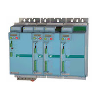
Parker 890CD Quick Start Manual (33 pages)
890 series (Common Bus) Drives Frames B, C & D with STO SIL3/PLe
Brand:
Parker
| Category:
Controller
| Size: 6 MB
Table of Contents
Table of Contents
2
Safety
3
Hazards to Personnel
3
Application Risk
3
Risk Assessment
4
Accessibility
4
Protective Insulation
4
Rcds
4
Introduction
5
About this Quickstart
5
Ssd_Rail
6
Installation
7
Dimensions
8
Ventilation
8
Environmental Conditions
8
Overview
9
890CS Power Connections
10
890CD Power Connections
11
Ssd_Rail Connections
12
Busbar Installation
12
890CS Control Connections
13
890CD Control Connections
14
890CD Feedback Connections
15
Drive Start-Up
16
Before Applying Power
16
Powering-Up the 890CS
17
Powering-Up each 890CD
17
890CD Set-Up
17
Quick Setup Parameters
18
Autotune
18
Running in Local
19
Running in Remote
19
Appendix A: Using the 6511 Keypad
20
The Menu Structure
21
890Cs
21
890Cd
22
Appendix B: Using the 6901 Keypad
23
The Menu Structure
24
890Cd
24
890Cs
25
Appendix C: Analog and Digital I/O
27
Appendix C: Analog and Digital I/O
27
890CD Control Terminals
27
890CS Control Terminals
28
890SD Control Terminals
28
890CS Control Terminals
29
Appendix D: Electrical Ratings
30
890CS Common Bus Supply
30
Appendix D: Electrical Ratings
30
890CD Common Bus Drive
31
Advertisement
Related Products
Parker 890CS
Parker 890SD
Parker 890 Series
Parker 8903/SP
Parker 8903/DN
Parker Hauser COMPAX 85XXS Series
Parker 890CA
Parker 8903/IM
Parker 8902/EQ
Parker 8902/LS
Parker Categories
Controller
Control Unit
Industrial Equipment
Water Filtration Systems
DC Drives
More Parker Manuals
Login
Sign In
OR
Sign in with Facebook
Sign in with Google
Upload manual
Upload from disk
Upload from URL