Sign In
Upload
Manuals
Brands
Panasonic Manuals
Fax Machine
KX-FP215
Panasonic KX-FP215 Manuals
Manuals and User Guides for Panasonic KX-FP215. We have
2
Panasonic KX-FP215 manuals available for free PDF download: Service Manual, Operating Instructions Manual
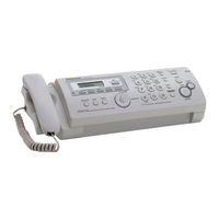
Panasonic KX-FP215 Service Manual (236 pages)
Compact Plain Paper Fax with Digital Answering System
Brand:
Panasonic
| Category:
Fax Machine
| Size: 6.78 MB
Table of Contents
Table of Contents
2
1 Safety Precautions
5
For Service Technicians
5
AC Caution
5
Personal Safety Precautions
6
Moving Sections of the Unit
6
Live Electrical Sections
6
Service Precautions
7
Precautions to Prevent Damage from Static Electricity
7
2 Warning
8
About Lead Free Solder (Pbf: Pb Free)
8
Suggested Pbf Solder
8
Insulation Resistance Test
9
Battery Caution
9
Discarding of P. C. Board
9
3 Specifications
10
4 General/Introduction
11
Optional Accessories
11
5 Features
11
Replacement Parts List
11
6 Technical Descriptions
12
Connection Diagram
12
General Block
13
General Block Diagram
14
Control Section
15
Block Diagram
15
Memory Map
16
Asic (Ic501)
17
Flash Memory (IC506)
20
Dynamic RAM (IC503)
20
Reset Circuit (Watch Dog Timer)
21
RTC Backup Circuit
22
Supervision Circuit for the Thermal Head Temperature
23
Facsimile Section
24
Image Data Flow During Facsimile Operation
24
Block Diagram
25
Thermal Head
26
Scanning Block
28
Stepping Motor Drive Circuit
29
Sensors and Switches
31
Document Top Sensor (SW351)
32
Document Set Sensor (SW352)
32
Paper Top Sensor (SW1001)
33
Cover Open Sensor (SW1001)
33
Film End Sensor (SW1003)
34
Motor Position Sensor (SW1004)
34
Hook Switch (SW1501)
34
Modem Section
35
Function
35
Modem Circuit Operation
41
NCU Section
42
General
42
EXT. TEL. Line Relay (RLY101)
42
Bell Detection Circuit
42
Pulse Dial Circuit and ON/OFF Hook Circuit
42
Line Amplifier and Side Tone Circuit
43
Auto Disconnect Circuit
43
Calling Line Identification Circuit
44
Its
45
Monitor Section
45
General
45
Speakerphone Circuit
45
Handset Circuit
45
Monitor Circuit for each Signals
45
Operation Board Section
46
LCD Section
47
Power Supply Board Section
48
Location of Controls and Components
51
Overview
51
Control Panel
51
8 Installation Instructions
52
Installation Space
52
Connections
53
Installing the Ink Film
53
Installing the Paper Tray
55
Paper Support
55
Installing the Recording Paper
56
9 Operating Instructions
57
Setting Your Logo
57
Test Mode
58
DTMF Signal Tone Transmit Selection
59
Button Code Table
60
Print Test Pattern
61
Service Mode
62
Programing and Lists
62
Operation
62
Operation Flow
62
Service Function Table
63
Memory Clear Specification
65
The Example of the Printed List
66
User Mode
66
Service Mode Settings
67
History
68
12 Troubleshooting Guide
70
Troubleshooting Summary
70
Precautions
70
Error Messages-Display
71
Error Messages-Report
73
Journal Report
73
Special Service Journal Report
82
Communication Section
86
Remote Programming
95
Entering the Remote Programming Mode and Changing Service Codes
95
Program Mode Table
96
Troubleshooting Details
98
Outline
98
Starting Troubleshooting
98
Troubleshooting Items Table
99
ADF (Auto Document Feed) Section
101
Digital Board Section
114
Analog Board Section
121
Digital Speakerphone
123
Power Supply Board Section
125
Operation Panel Section
128
Sensor Section
129
CIS (Contact Image Sensor) Section
131
Thermal Head Section
132
13 Service Fixture & Tools
133
14 Disassembly and Assembly Instructions
134
General Section
134
Disassembly Flowchart
135
Upper Cabinet Section
135
Lower Cabinet Section
135
Back Cover Section
136
Operation Panel Section
136
Disassembly Procedure
137
How to Remove the Image Sensor (CIS)
137
How to Remove the Thermal Head
138
How to Remove the Bottom Frame
140
How to Remove the P.C. Boards and Speaker
141
How to Remove the Power Supply Board and AC Cord
142
How to Remove the Gear Block and Separation Roller
143
How to Remove the Gears, Motors and Arms of the Gear Block
144
How to Remove the Handset Cradle and Hook Switch Board
146
How to Remove the Platen Roller and Lock Lever
147
How to Remove the Pickup Roller
150
How to Remove the Operation Panel
151
Lcd
152
How to Remove the Separation Holder and Exit Roller
153
Installation Position of the Lead Wires
154
15 Maintenance
158
Maintenance Items and Component Locations
158
Outline
158
Component Locations
158
Gear Section
160
Mode Selection
160
Mode Operation
161
Mechanical Movements
164
Receiving Faxes and Copying)
164
Jams
167
Recording Paper Jams
167
Document Jams - Sending
168
Cleaning
169
Document Feeder/Recording Paper Feeder/Scanner Glass Cleaning
169
Thermal Head Cleaning
170
16 Miscellaneous
171
Terminal Guide of the Ics Transistors and Diodes
171
Digital Board
171
Analog Board
171
Operation Board
171
Power Supply Board
172
Interface Board
172
How to Replace the Flat Package IC
173
Preparation
173
Flat Package IC Removal Procedure
173
Flat Package IC Installation Procedure
173
Bridge Modification Procedure
173
Test Chart
174
ITU-T No.1 Test Chart
174
ITU-T No.2 Test Chart
175
Test Chart
176
17 Schematic Diagram
178
Digital Board (PCB1)
178
Analog Board (PCB2)
182
Operation Board (PCB3)
184
Power Supply Board (PCB4)
185
Interface Board (PCB5)
186
Sensor Board (PCB6)
187
Film End Sensor Board (PCB7)
187
Motor Position Sensor Board (PCB8)
187
Hook Switch Board (PCB9)
188
18 Printed Circuit Board
189
Digital Board (PCB1)
189
Bottom View
189
Component View
190
Analog Board (PCB2)
191
Bottom View
191
Component View
192
Operation Board (PCB3)
193
Power Supply Board (PCB4)
194
Interface Board (PCB5)
195
Sensor Board (PCB6)
195
Film End Sensor Board (PCB7)
195
Motor Position Sensor Board (PCB8)
195
Hook Switch Board (PCB9)
196
19 Appendix Information of Schematic Diagram
196
20 Exploded View and Replacement Parts List
197
Cabinet, Mechanical and Electrical Parts Location
197
General Section
197
Operation Panel Section
198
Upper Cabinet Section
199
Back Cover Section
200
Lower Cabinet Section
202
Gear Block Section
203
Screws
204
Accessories and Packing Materials
205
Replacement Parts List
206
Cabinet and Electrical Parts
206
Digital Board Parts
207
Analog Board Parts
209
Operation Board Parts
210
Power Supply Board Parts
211
Interface Board Parts
211
Sensor Board Parts
211
Film End Sensor Board Parts
211
Motor Position Sensor Board Parts
212
Hook Swicth Board Parts
212
MIC Board Parts
212
Replacement Parts List
214
Reference Chart
214
Original and New Parts Comparison Lists
214
Changes
216
Schematic Diagram
216
Digital Board (PCB1)
216
Printed Circuit Board
221
Bottom View
221
Component View
222
Digital Board Parts
227
Advertisement
Panasonic KX-FP215 Operating Instructions Manual (60 pages)
Compact Plain Paper Fax and Copier with Digital Answering System
Brand:
Panasonic
| Category:
Fax Machine
| Size: 5.98 MB
Table of Contents
Operating Instructions
1
Important Information
4
Table of Contents
6
1 Table of Contents
7
Introduction and Installation
8
Included Accessories
8
Accessory Information
8
Button Descriptions
9
Overview
10
Ink Film
10
Handset Cord
12
Paper Tray
12
Paper Support
12
Recording Paper
13
2 Preparation
14
Connections
14
Quick Setup
15
Help Function
15
Adjusting Volume
16
Date and Time
16
Your Logo
17
Your Fax Number
18
3 Telephone
19
Storing Names and Telephone Numbers into the Phonebook
19
Making a Phone Call Using the Phonebook
19
Editing a Stored Item
19
Erasing a Stored Item
19
One Touch Dial
19
Caller ID
20
Caller ID Service
20
Viewing and Calling Back
21
Caller ID Number Auto Edit Feature
21
Erasing Caller Information
21
Storing Caller Information into the Phonebook
22
4 Fax
23
Sending a Fax Manually
23
Document Requirements
24
Sending a Fax Using the Phonebook and One Touch Dial
24
Broadcast Transmission
25
Selecting the Way to Use Your Fax Machine
26
Receiving a Fax Manually - Auto Answer off
27
Receiving a Fax Automatically - Auto Answer on
27
Junk Fax Prohibitor (Preventing Fax Reception from Undesired Callers)
28
5 Distinctive Ring
30
Distinctive Ring Service
30
Using Two or more Phone Numbers on a Single Telephone Line
30
Using Three or more Phone Numbers on a Single Telephone Line
30
Programming the Ring Pattern Assigned for Fax
30
6 Copy
31
Making a Copy
31
7 Answering Machine
33
Recording Your Greeting Message
33
Incoming Messages
33
Listening to Recorded Messages
34
Leaving a Message for Others or Yourself
34
Remote Operation
35
Operating from a Remote Location
35
8 Programmable Features
36
Programming
36
Basic Features
37
Advanced Features
38
9 Help
42
Error Messages - Reports
42
Error Messages - Display
43
When a Function Does Not Work, Check here
44
10 Maintenance
49
Recording Paper Jams
49
Document Jams
50
Cleaning
51
Document Feeder/Recording Paper Feeder/Scanner Glass Cleaning
51
Thermal Head Cleaning
52
11 General Information
53
Reference Lists and Reports
53
Specifications
53
FCC and Other Information
55
Limited Warranty
56
Limited Warranty (United States and Puerto Rico)
56
Customer Services
57
Customer Services Directory
57
Advertisement
Related Products
Panasonic KX-FP215AL
PANASONIC KX-FP218FX
Panasonic KX-FP218CX
Panasonic KX-FP215C
Panasonic KX-FP215E
Panasonic KX-FP218FX-S
Panasonic KX-FP218
Panasonic KX-FP206CX
Panasonic KX-FP245
Panasonic KX-FP205AL
Panasonic Categories
Camcorder
Air Conditioner
TV
Digital Camera
Cordless Telephone
More Panasonic Manuals
Login
Sign In
OR
Sign in with Facebook
Sign in with Google
Upload manual
Upload from disk
Upload from URL