Sign In
Upload
Manuals
Brands
Oshkosh Corporation Manuals
Lifting Systems
JLG H800AJ
Oshkosh Corporation JLG H800AJ Manuals
Manuals and User Guides for Oshkosh Corporation JLG H800AJ. We have
4
Oshkosh Corporation JLG H800AJ manuals available for free PDF download: Illustrated Parts Manual, Service And Maintenance Manual, Operation And Safety Manual
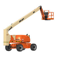
Oshkosh Corporation JLG H800AJ Service And Maintenance Manual (339 pages)
Brand:
Oshkosh Corporation
| Category:
Boom Lifts
| Size: 36 MB
Table of Contents
Table of Contents
6
Chassis & Turntable
55
Tires & Wheels
55
Tire Damage
55
Tire Replacement
55
Wheel Replacement
55
Wheel Installation
55
Powertrain Operating Modes
56
Hybrid Mode
56
Electric Mode
56
Switching between Modes on the Fly
56
Idle Reduction Stop Start
57
Drive Orientation System
58
Oscillating Axle System
58
Lockout Cylinder Bleeding
59
Oscillating Axle Lockout Test
62
Drive System
64
Drive Hub (Torque)
66
Removal
66
Installation
66
Drive Hub
66
Assembly/Disassembly
66
Drive Brake
66
Drive Motor
66
Removal
67
Installation
67
Description
67
Shaft Seal Replacement
67
Loop Flushing Valve
68
Troubleshooting
69
Disassembly
70
Inspection
74
Assembly
76
Initial Start-Up Procedures
81
Swing Drive
84
Roll, Leak and Brake Testing
84
Tightening and Torquing Bolts
85
Motor Control Valve Disassembly
86
Motor and Brake Disassembly
87
Main Drive Disassembly
88
Hub-Shaft Disassembly
89
Carrier Disassembly
90
Hub-Shaft Assembly
91
Carrier Assembly
91
Main Drive Assembly
92
Motor and Brake Assembly
93
Motor Control Valve Assembly
94
Swing Motor
101
Disassembly and Inspection
101
Assembly
108
One Piece Stator Construction
116
Swing Hub Installation
117
Procedure for Setting Swing Gear Backlash
117
Swing Drive Lubrication
118
Swing Hub Removal
118
Swing Bearing
119
Turntable Bearing Mounting Bolt Condition Check
119
Wear Tolerance
122
Swing Bearing Replacement
122
Swing Bearing Torque Values
123
Chassis Tilt Indicator System
125
Rotary Coupling
126
Generator
132
Maintenance Schedule
132
Overload Protection
133
Inspecting Brushes, Replacing Brushes, and Cleaning Slip Rings
133
Troubleshooting
135
Generator Disassembly and Assembly
136
Lead Connection List for Generator
144
Cold Start System
150
Engine Warmup
150
Clutch Adapter Plate Installation
150
Clutch Kit & Release Shaft Installation
151
Clutch Kit
151
Release Shaft
152
Clutch Installation
153
Clutch Linear Actuator/Throwout Bearing Positioning Installation Procedure
153
Counterweight
156
Boom & Platform
158
Boom Systems
158
Switch Systems
158
Above Elevation (above Horizontal) Cutout System
158
Beyond Transport Position - Drive Speed Cutback System
158
Drive/Steer - Boom Function Interlock System (CE Only)
158
Transport Position Interlock System (CE Only)
158
Platform Control Enable System
158
Function Speed Control System
158
Platform
159
Main Lift End Stroke Dampening System
159
Quikstick Lift System
159
Tower Boom Sequence Valve System
159
Upright Level Override System
159
Ground Control Keyswitch System
159
Main Boom Assembly
163
Removal
163
Disassembly
164
Inspection
164
Assembly
164
Installation
165
Upright
166
Removal
166
Installation
167
Tower Boom Assembly
169
Removal
169
Inspection
169
Assembly
170
Installation
170
Tower out of Sync
171
Upright Monitoring System (UMS)
173
Re-Synchronizing Upright
173
Calibration
175
Calibration Faults
179
Function Check
179
Service Mode/Tower Boom Retrieval
181
UMS Troubleshooting and Diagnostic Trouble Codes (DTC)
185
Backward Stability Concern DTC (2532)
185
Forward Stability Concern DTC (2530)
185
Out of Usable Range DTC (2531)
185
UMS Sensor Not Calibrated DTC (816)
185
UMS Sensor Faulted DTC (817)
185
Calibration Faults
185
Platform
186
Platform Valve Removal
186
Platform Valve Installation
186
Platform Support Removal
187
Support Installation
188
Bolt-On External Fall Arrest
190
Inspection before Use
190
Installation
190
Articulating Jib
192
Removal
192
Disassembly
192
Inspection
192
Assembly
193
Installation
193
Rotator and Slave Cylinder
194
Removal
194
Installation
194
Sequence for Hose Replacement in the Tower Boom
195
Limit Switches Adjustment
195
Main Boom Horizontal Limit Switch
195
Tower Boom Horizontal Limit Switch
195
Boom Valve Adjustment
199
Tower Boom
199
Main Boom
199
Boom Cleanliness Guidelines
200
Main Boom Powertrack
201
Removal
201
Installation
201
Powertrack Maintenance
206
Flat Bar Removal
206
Round Bar/Poly Bar Removal
206
Removing and Installing Links
207
Installing a New Flat Bar
210
Installing a New Round Bar/Poly Roller
211
Replacing a Fixed End Bracket
211
Replacing a Moving End Bracket
212
Replacing a One Piece Bracket
212
Rotator Assembly
214
Theory of Operation
214
Required Tools
214
Disassembly
217
Inspection
221
Assembly
221
Installing Counterbalance Valve
227
Greasing Thrust Washers
228
Testing the Actuator
228
Installation and Bleeding
229
Foot Switch Adjustment
229
Troubleshooting
230
Skyguard
231
Operation
231
Function Test
231
Diagnostics & Troubleshooting
232
Basic Hydraulic Information & Hydraulic Schematics
234
Lubricating O-Rings in the Hydraulic System
234
Cup and Brush
234
Dip Method
235
Spray Method
235
Brush-On Method
235
Hydraulic Connection Assembly and Torque Specification
236
Tapered Thread Types
236
Straight Thread Types, Tube and Hose Connections
236
Straight Thread Types, Port Connections
237
Flange Connection Types
237
Tightening Methods
237
Assembly and Torque Specifications
238
Assembly Instructions for American Standard Pipe Thread Tapered (NPTF) Connections
239
Assembly Instructions for British Standard Pipe Thread Tapered (BSPT) Connections
240
Assembly Instructions for 37° (JIC) Flare Fittings
241
Assembly Instructions for 45° SAE Flare Fittings
245
Assembly Instructions for O-Ring Face Seal (ORFS) Fittings
247
Assembly Instructions for DIN 24° Flare Bite Type Fittings (MBTL and MBTS)
249
Assembly Instructions for Bulkhead (BH) Fittings
251
Assembly Instructions for Metric ISO 6149 (MPP) Port Assembly Stud Ends
271
Assembly Instructions for Adjustable Port End (BSPP) Fittings
273
Assembly Instructions for Flange Connections: (FL61 and FL62)
281
Double Wrench Method
284
FFWR and TFFT Methods
285
Adjustable Stud End Assembly
285
O-Ring Installation (Replacement)
286
Hydraulic Cylinders
287
Axle Lockout Cylinder
287
Slave Cylinder
289
Upright Level Cylinder
295
Jib Lift Cylinder
296
Main Boom Lift Cylinder
302
Tower Boom Lift Cylinder
303
Master Cylinder
304
Cleaning and Inspection
306
Main Boom Telescope Cylinder
315
Tower Boom Telescope Cylinder
321
Cylinder Removal and Installation
327
Main Boom Telescope Cylinder Removal
327
Main Boom Telescope Cylinder Installation
329
Main Lift Cylinder Removal
330
Main Lift Cylinder Installation
331
Upright Level Cylinder Removal
332
Upright Level Cylinder Installation
333
Tower Boom Lift Cylinder Removal
333
Tower Boom Lift Cylinder Installation
334
Tower Telescope Cylinder Removal
335
Tower Telescope Cylinder Installation
335
Master Cylinder Removal
336
Master Cylinder Installation
336
Pressure Setting Procedures
337
Set up the Function Pump
337
Adjustments Made at the Main Valve Block
338
Adjustments Made at the Platform Valve Block
338
Advertisement
Oshkosh Corporation JLG H800AJ Illustrated Parts Manual (484 pages)
Brand:
Oshkosh Corporation
| Category:
Lifting Systems
| Size: 14 MB
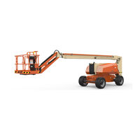
Oshkosh Corporation JLG H800AJ Operation And Safety Manual (145 pages)
Brand:
Oshkosh Corporation
| Category:
Boom Lifts
| Size: 15 MB
Table of Contents
Table of Contents
8
Section 1. Safety Precautions
15
General
15
Pre-Operation
15
Operator Training and Knowledge
15
Workplace Inspection
16
Machine Inspection
17
Operation
17
General
17
Trip and Fall Hazards
18
Electrocution Hazards
19
Minimum Approach Distances (M.A.D.)
20
Tipping Hazards
21
Beaufort Scale (for Reference Only)
23
Crushing and Collision Hazards
24
Towing, Lifting, and Hauling
25
Maintenance
25
Maintenance Hazards
25
Battery Hazards
26
Section 2 - User Responsibilities, Machine Preparation, and Inspection
28
2.1 Personnel Training
28
Operator Training
28
Training Supervision
28
Operator Responsibility
29
Machine Familiarization
29
Preparation, Inspection, and Maintenance
29
Inspection and Maintenance Table
30
Basic Nomenclature
31
Pre-Start Inspection
32
Daily Walk-Around Inspection
34
Walk-Around Inspection
35
Function Check
36
Tower Boom Vertical Limit Switch
37
Tower Boom Horizontal Limit Switch
38
Skyguard Function Test
41
Oscillating Axle Lockout Test (if Equipped)
43
Section 3 - Machine Controls and Indicators
45
General
45
Controls and Indicators
45
Ground Control Console
46
Ground Control Console
47
Ground Control Indicator Panel
51
Ground Control Indicator Panel
52
Ground Control Console Display Gauge
54
Splash Screen
54
Diagnostic Screen
55
Engine Diagnostic Screen
55
Ground Control Console Display Gauge
56
Platform Control Console
57
Platform Console
58
Platform Console Indicator Panel
63
Section 4 - Machine Operation
67
Description
67
Operating Characteristics and Limitations
67
Capacities
67
Platform Load Sensing System (LSS)
68
Stability
68
Position of Least Forward Stability
69
Positions of Least Backward Stability (Sheet 1 of 2)
70
Positions of Least Backward Stability (Sheet 2 of 2)
71
Engine Operation
72
Starting Procedure
72
Shutdown Procedure
73
Engine Warmup
74
Powertrain Operating Modes
74
HYBRID Mode
74
ELECTRIC Mode
75
Switching between Modes
76
Grade and Sideslopes
77
Traveling (Driving)
78
Traveling Forward and Reverse
79
Traveling on a Grade
80
Steering
80
Platform
80
Platform Level Adjustment
80
Platform Rotation
80
Boom
81
Swinging the Boom
81
Raising and Lowering the Tower Boom
81
Raising and Lowering the Main Boom
83
Telescoping the Main Boom
83
Battery Charging
83
Machine Safety System Override (Msso)
84
(Ce Only)
84
4.10 Skyguard Operation
84
Skyguard
84
Skyguard - Skyline
84
Skyguard - Skyeye
85
Skyguard Function Table
85
Shut down and Park
86
4.11 Lifting and Tie down
86
Lifting
86
Tie down
87
Lifting Chart
88
Towing
90
Tow Bar (if Equipped)
90
4.10 Re-Synchronize Upright
90
Releveling Valve
90
Tow Bar
90
Releveling Valve
91
Decal Legend
103
Section 5 - Emergency Procedures
108
General
108
Incident Notification
108
Emergency Operation
108
Operator Unable to Control Machine
108
Platform or Boom Caught Overhead
109
Emergency Towing Procedures
109
Machine Safety System Override (Msso)
110
(Ce Only)
110
Section 6 - Accessories
112
Available Accessories
112
Options/Accessories Relationship Table
113
Fall Arrest Platform
114
Safety Precautions
114
Skyglazier
114
Capacity Specifications
115
Safety Precautions
115
Preparation and Inspection
116
Operation
116
Skypower
116
Generator Output
117
Safety Precautions
117
Preparation and Inspection
118
Operation
118
Skywelder
118
Generator Output
119
Welding Accessories
119
Accessory Ratings
120
Safety Precautions
120
Preparation and Inspection
121
Operation
121
Soft Touch
121
Section 7 - General Specifications & Operator Maintenance
124
Introduction
124
Operating Specifications and Performance
124
Data
124
Operating Specifications
124
Tires
125
Batteries
125
Tire Specifications
125
Battery Specifications
125
Capacities
126
Engine Data
126
Kubota D1305
126
Hydraulic Oil
127
Mobilfluid 424 Specs
127
Mobil DTE 10 Excel 32 Specs
128
Ucon Hydrolube HP-5046
128
Mobil EAL 224H Specs
129
Exxon Univis HVI 26 Specs
129
Critical Stability Weights
130
Hydraulic Oil Operating Temperature Specifications
132
Hydraulic Oil Operating Temperature Specifications
133
Maintenance and Lubrication Diagram
134
Maintenance and Lubrication
135
Lubrication Specifications
135
Tires & Wheels
141
Tire Damage
141
Tire Replacement
141
Wheel Replacement
141
Wheel Installation
142
Supplemental Information
143
Wheel Torque Chart
143
Advertisement
Oshkosh Corporation JLG H800AJ Operation And Safety Manual (164 pages)
Brand:
Oshkosh Corporation
| Category:
Boom Lifts
| Size: 9 MB
Table of Contents
Table of Contents
7
Section 1. Safety Precautions
15
General
15
Pre-Operation
15
Operator Training and Knowledge
15
Workplace Inspection
16
Machine Inspection
17
Operation
17
General
17
Trip and Fall Hazards
18
Electrocution Hazards
19
Tipping Hazards
21
Crushing and Collision Hazards
24
Towing, Lifting, and Hauling
25
Maintenance
25
Maintenance Hazards
25
Battery Hazards
27
Section 2 - User Responsibilities, Machine Preparation, and Inspection
29
2.1 Personnel Training
29
Operator Training
29
Training Supervision
29
Operator Responsibility
29
2.2 Preparation, Inspection, and Maintenance
30
Pre-Start Inspection
33
Walk-Around Inspection
35
Function Check
39
From the Ground Control Console with no Load in the Platform
39
From the Platform Control Console
43
Skyguard Function Test
45
Oscillating Axle Lockout Test (if Equipped)
46
Section 3 - Machine Controls and Indicators
49
General
49
Controls and Indicators
49
Ground Control Console
50
Ground Control Indicator Panel
56
Ground Control Console Display Gauge
59
Platform Console
62
Platform Console Indicator Panel
68
Section 4 - Machine Operation
73
Description
73
Boom Operating Characteristics and Limitations
73
Capacities
73
Stability
73
Engine Operation
77
Starting Procedure
77
Shutdown Procedure
78
Engine Warmup
78
Powertrain Operating Modes
79
HYBRID Mode
79
ELECTRIC Mode
80
Switching between Modes
80
Traveling (Driving)
81
Traveling Forward and Reverse
83
Traveling on a Grade
84
Steering
84
Platform
84
Platform Level Adjustment
84
Platform Rotation
84
Boom
85
Swinging the Boom
85
Raising and Lowering the Tower Boom
86
Raising and Lowering the Main Boom
87
Telescoping the Main Boom
87
Shut down and Park
87
Battery Charging
88
Machine Safety System Override (Msso)
89
4.10 Skyguard Operation
89
4.11 Lifting and Tie down
91
Lifting
91
Tie down
91
Towing
93
Tow Bar (if Equipped)
93
4.10 Re-Synchronize Upright
95
Releveling Valve
95
Section 5 - Emergency Procedures
121
General
121
Incident Notification
121
Emergency Operation
121
Operator Unable to Control Machine
121
Platform or Boom Caught Overhead
122
Emergency Towing Procedures
122
Section 6 - Accessories
125
Fall Arrest Platform
127
Safety Precautions
127
Pipe Racks
127
Capacity Specifications (Australia Only)
128
Safety Precautions
128
Preparation and Inspection
128
Operation
128
Skyglazier
129
Capacity Specifications
129
Safety Precautions
130
Preparation and Inspection
130
Operation
130
Skypower
131
Generator Output
131
Safety Precautions
132
Preparation and Inspection
132
Operation
132
Skywelder
133
Generator Output
133
Welding Accessories
133
Accessory Ratings
134
Safety Precautions
134
Preparation and Inspection
135
Operation
135
Soft Touch
135
Section 7 - General Specifications & Operator Maintenance
137
Introduction
137
Operating Specifications and Performance
137
Data
137
Operating Specifications
137
Tires
138
Batteries
138
Capacities
139
Engine Data
139
Hydraulic Oil
140
Critical Stability Weights
143
Maintenance and Lubrication
148
Tires & Wheels
154
Tire Inflation
154
Tire Damage
154
Tire Replacement
154
Wheel Replacement
155
Wheel Installation
155
Supplemental Information
157
Section 8 - Inspection and Repair Log
159
Advertisement
Related Products
Oshkosh Corporation JLG H600SJ
Oshkosh Corporation JLG 3394RT
Oshkosh Corporation JLG 439RT
Oshkosh Corporation JLG 830P
Oshkosh Corporation JLG 19BD
Oshkosh Corporation JLG 1030S
Oshkosh Corporation JLG 1100SJ
Oshkosh Corporation JLG 20MVL
Oshkosh Corporation JLG AE1932
Oshkosh Corporation JLG EcoLift 70
Oshkosh Corporation Categories
Boom Lifts
Lifting Systems
Scissor Lifts
Industrial Equipment
Air Compressor
More Oshkosh Corporation Manuals
Login
Sign In
OR
Sign in with Facebook
Sign in with Google
Upload manual
Upload from disk
Upload from URL