Sign In
Upload
Manuals
Brands
Omron Manuals
Controller
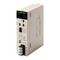
SYSMAC CS1W-RPT03
Omron SYSMAC CS1W-RPT03 Optic Repeater Manuals
Manuals and User Guides for Omron SYSMAC CS1W-RPT03 Optic Repeater. We have
1
Omron SYSMAC CS1W-RPT03 Optic Repeater manual available for free PDF download: Operation Manual
Omron SYSMAC CS1W-RPT03 Operation Manual (401 pages)
Controller Link Units
Brand:
Omron
| Category:
Controller
| Size: 4 MB
Table of Contents
Precautions
20
Table of Contents
20
Intended Audience
21
General Precautions
21
Safety Precautions
21
Operating Environment Precautions
22
Applications Precautions
23
Section 1 Features and System Configuration
26
Overview
27
What Is the Controller Link
27
Features
33
Specifications and Configurations
37
System Configuration
37
General Specifications
39
Communications Specifications
40
Controller Link Unit Models and Plcs
43
Devices for Connection
46
Programming Devices
48
Basic Procedures
52
Selection of Communications Functions
52
Application Precautions
54
Section 3 Installation and Wiring
70
Component Names and Functions
71
CS-Series Controller Link Units (CS1W-CLK23 and CS1W-CLK21-V1)
71
CJ-Series Controller Link Units (CJ1W-CLK23 and CJ1W-CLK21-V1)
73
C200HX/HG/HE Controller Link Unit
76
CVM1 and CV-Series Controller Link Unit
78
CQM1H-Series Controller Link Unit
80
Wire-To-Wire Repeater Unit
81
Wire-To-Optical (H-PCF) Repeater Unit
83
Wire-To-Optical (GI) Repeater Unit
84
Unit Installation
85
Mounting Controller Link Units
86
Mounting a Repeater Unit
91
Wiring
93
Communications Cables
93
Repeater Units
98
Constructing Networks with Repeater Units
105
Segments
106
Number of Repeater Units
107
Terminating Resistance
109
Section 4 Preparations for Communications
112
CS-Series Controller Link Units
113
Overview
113
Unit Number
113
Node Addresses
114
Baud Rates
115
Terminating Resistance
116
CJ-Series Controller Link Units
116
Overview
117
Unit Number
117
Node Addresses
118
Baud Rates
119
Terminating Resistance
119
C200HX/HG/HE Controller Link Units
120
Overview
121
Node Addresses
121
Baud Rates and Operating Levels
122
Terminating Resistance
123
CVM1 and CV-Series Controller Link Units
124
Overview
124
Unit Number
125
Node Addresses
125
Baud Rates
126
Terminating Resistance
126
CQM1H-Series Controller Link Units
127
Overview
127
Node Addresses
128
Baud Rates
128
Terminating Resistance
129
Repeater Units
129
Wire-To-Wire Repeater Unit
130
Baud Rates
130
Terminating Resistance
131
Section 5 Data Links
132
What Are Data Links
133
Data Link Specifications
138
Differences between Manual and Automatic Setting
139
Setting Data Links
140
Selecting Manual or Automatic Setting
140
Manual Setting
141
Manual Setting Examples
150
Automatic Setting
156
Automatic Setting Example
178
Starting and Stopping Data Links
180
Using a Programming Device or the User Program
181
Using the Controller Link Support Software and CX-Programmer
182
Using FINS Commands
182
Checking Data Link Status
183
LED Indicators
183
Data Link Status Area
183
Data Link Status Area
188
Checking by Manipulating Bit/Word Status
188
Error Detection Program Example
189
Programming Examples for Processing Data When Errors Occur
189
Section 6 Message Service
192
Introduction
193
SEND and RECV
194
CMND (CVM1, CV-Series, CS/CJ-Series, and CQM1H-Series Plcs Only)
207
Send/Receive Data Areas
212
Selecting Communications Instructions
214
Message Service Operations
215
Message Service Specifications
216
Using the Message Service
217
FINS Commands and Responses
227
FINS Communications Service
227
Sending and Receiving FINS Commands and Responses
227
Applicable Units for FINS Commands
228
Commands and Responses for Controller Link Units
229
Command Codes
229
Data Link Start
229
Data Link Stop
229
Controller Data Read
230
Controller Status Read
231
Network Status Read
233
Data Link Status Read
235
Echoback Test
237
Broadcast Test Results Read
237
6-5-10 Broadcast Test Data Send
238
6-5-11 Error Log Read
238
6-5-12 Error Log Clear
239
Commands and Responses for C200HX/HG/HE and CQM1H-Series Plcs
240
Command Codes
240
Memory Area Designations
240
Memory Area Read
242
Memory Area Write
243
Multiple Memory Area Read
244
Program Area Read
244
Program Area Write
245
Run
246
Stop
246
6-6-10 Controller Data Read
247
6-6-11 Controller Status Read
248
6-6-12 Clock Read
249
6-6-13 Clock Write
249
6-6-14 Error Clear
250
6-6-15 Forced Set/Reset
250
6-6-16 Forced Set/Reset Cancel
251
6-6-17 Multiple Forced Status Read
252
Response Codes
253
Configuration
253
Network Relay Errors
254
Response Codes and Troubleshooting
255
Section 7 Network Interconnections
262
What Is Network Interconnection
263
Interconnecting Controller Link Networks
263
Interconnecting Different Types of Networks
263
Remote Programming and Monitoring
265
Local Networks
265
Remote Controller Link Networks
266
Other Remote Networks
267
Routing Tables
268
Setting Routing Tables
269
Routing Table Setting Procedure
270
Editing Local Network Tables
270
Editing Relay Network Tables
271
Saving Routing Tables
271
Connecting to the PLC
272
Routing Table Enable Bit (C200HX/HG/HE and CQM1H-Series Only)
272
Transferring Routing Tables
272
Example Routing Table Settings
273
Section 8 Communications Timing
276
Communications Mechanism
277
Data Transmissions over the Network
277
Setting the Polling and Polled Nodes
278
Network Parameters
279
Specifying Network Parameters
280
Communications Cycle Time
280
Active Data Links
280
Inactive Data Links
281
Data Link I/O Response Time
282
Data Exchange Timing
282
Data Processing Time
283
Calculation Example
284
Message Delay Times
289
CS/CJ-Series, CVM1, and CV-Series Plcs
289
C200HX/HG/HE and CQM1H-Series Plcs
293
Section 9 Troubleshooting and Maintenance
298
Troubleshooting Using Indicators
299
CS/CJ-Series Controller Link Units
299
C200HX/HG/HE and CQM1H-Series Controller Link Units
306
CVM1 and CV-Series Controller Link Units
310
Repeater Units
314
Status Area and Troubleshooting
315
CS/CJ-Series Controller Link Units
316
C200HX/HG/HE Controller Link Units
321
CVM1 and CV-Series Controller Link Units
327
CQM1H-Series Controller Link Units
331
Error Log
335
Error Log Table
335
Error Codes
336
Reading and Clearing Error Logs
342
Troubleshooting Error Messages in CX-Net Data Link Table Check
343
Cleaning and Inspection
345
Cleaning
346
Inspection
346
Handling Precautions
346
Replacing the Unit
347
Setting the Unit after Replacement
348
Replacing the Unit
350
Section 10 Adding Nodes and Editing Active Data Link Tables
354
10-1 Adding Nodes Using a Repeater Unit
355
10-1-1 Overview
355
10-1-2 Procedure for Adding Nodes
356
10-1-3 Precautions When Connecting Nodes Using a Repeater Unit
356
10-2 Changing the Data Link Tables with Active Data Links
359
10-2-1 Overview
359
10-2-2 Example of Changing Data Link Table with Active Data Links
359
10-2-3 Operations When Changing Data Link Tables
359
(Theoretical)
360
Procedure for Changing the Data Link Tables with CX-Programmer
361
Advertisement
Advertisement
Related Products
Omron SYSMAC CS1W-RPT02
Omron CS1W-DRM21-V1
Omron CS1W-FLN22
Omron CS1W-EIP21 100Base-TX
Omron CS1W-SCB41
Omron SYSMAC CS1W-CLK23
Omron SYSMAC CS1W-CLK11
Omron SYSMAC CS1W-CLK21
Omron SYSMAC CS1W-CLK13
Omron SYSMAC CS1W-CLK53
Omron Categories
Blood Pressure Monitor
Controller
Accessories
Switch
Inverter
More Omron Manuals
Login
Sign In
OR
Sign in with Facebook
Sign in with Google
Upload manual
Upload from disk
Upload from URL