Sign In
Upload
Manuals
Brands
Omega Manuals
Network Hardware
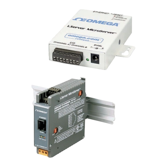
iServer Microserver
Omega iServer Microserver Manuals
Manuals and User Guides for Omega iServer Microserver. We have
1
Omega iServer Microserver manual available for free PDF download: User Manual
Omega iServer Microserver User Manual (74 pages)
Brand:
Omega
| Category:
Network Hardware
| Size: 2 MB
Table of Contents
Table of Contents
3
List of Figures
5
List of Tables
5
Part 1: Introduction
8
Safety and EMC Considerations
8
Before You Begin
8
Description
8
Part 2 Hardware
9
Mounting
9
Mounting the Wall Mount Iserver
9
Figure 2.1 Mounting - Wall Mount Iserver
9
Mounting the DIN Rail Iserver
10
Removal from a DIN Rail
10
Figure 2.2 Mounting - DIN Rail Iserver
10
Figure 2.3 Removal - DIN Rail Iserver
10
DIP Switches
11
SW1 DIP Switch Usage
11
Figure 2.4A DIP Switch SW1 - Wall Mount Iserver
11
Figure 2.4B DIP Switch SW1 - DIN Rail Iserver
11
SW3 DIP Switch Usage
12
Figure 2.5A DIP Switch SW3 - Wall Mount Iserver
12
Figure 2.5B DIP Switch SW3 - DIN Rail Iserver
12
Parts of Iserver Unit
13
Figure 2.6 Parts of Iserver Unit
13
Table 2.1 Parts of Iserver Unit
13
Wiring
14
Figure 2.7A Wall Mount Iserver 8 Position Connector
14
Figure 2.7B DIN Rail Iserver 8 Position Connector
14
Network Communication Interfaces
15
Base-T RJ-45 Pinout
15
Base-T Crossover Wiring
15
Figure 2.8 RJ45 Pinout
15
Figure 2.9 10Base-T Crossover Cable Wiring
15
Part 3: Network Configuration
16
Network Protocols
16
Ethernet (MAC) Address
16
Figure 3.1 Labeling
16
Dhcp
17
Dns
17
Figure 3.2 DIP Switch SW1
17
IP Address
18
Default IP Address
18
Port Number
18
Part 4: Operations
19
Testing the Connection
19
Figure 4.1 Pinging the Iserver from MS-DOS Prompt
19
Iconnect Software
20
Figure 4.2 Assigning an IP Address Using Iconnect
20
Figure 4.3 Accessing the Iserver's Home Page
20
Setting a New IP Address over the Network
21
Figure 4.4 Access Control
21
Setup and Operation Using a Web Browser
22
Figure 4.5 Iserver Home Page Menu
22
Login
23
Java Runtime Environment 1.7 Setup Instructions
23
Figure 4.6 Login Password
23
Figure 4.7 Java 1.7.X Screen Shot
23
Browser Proxy Selection
24
Iserver Operation Basic Menus
25
Chart Descriptions
25
Figure 4.8 Chart Descriptions
25
Table 4.1 Message Item Window Description
27
Device Configuration Page Items' Description and Concepts of Setup
28
Figure 4.9 Configuration/Device Setup
28
Device Type/Mode Selection
29
Frequency Mode
29
Totalizer Mode
30
Figure 4.10 Example of Totalizer Mode
31
Batch Mode
32
Figure 4.11 Example of Batch Mode
33
A-B F Mode
34
Figure 4.12 Example of A-B F Mode
35
A-B T Mode
36
Figure 4.13 Example of A-B T Mode with Bar Chart
37
Quadrature Mode
38
Figure 4.14 Example of Quadrature Mode
39
Totalizer Gate Mode
40
Figure 4.15 Example of Totalizer Gate Mode
41
Setpoint, Alarm and Alarm Output Operation Config
42
Figure 4.16 Example of Setpoint / Alarm Configuration
42
SP1 Active Mode
42
SP1 Active Status
42
SP1 Dead Band
42
SP1 Latch Mode
42
SP1 Value
42
SP2 Active Mode
43
SP2 Active Status
43
SP2 Dead Band
43
SP2 Latch Mode
43
SP2 Value
43
Figure 4.17 Example of Title Definability Utility
43
Title Definability Utility
43
Operation Condition Parameters
44
Figure 4.18 Example of Operation Condition Parameters
44
A Debounce Time (Ms)
45
A Gate Time (Ms)
45
A Offset
45
A Scale
45
B Debounce Time (Ms)
45
B Gate Time (Ms)
45
B Offset
45
B Scale
45
Input Reading Scale & Offset
45
Combined A-B Mode
46
Counter Mode
46
Counting Mode
46
Decimal Point
46
Number of Digit
46
Reading Format
46
Terminal/Remote (Tunneling) Server Setup
47
Figure 4.19 Terminal / Remote (Tunneling) Server Setup
47
Number of Connections
47
Server Type
47
Tcp/Udp
47
Port
48
Remote Access
48
Remote IP Address
48
Remote Port
48
List of Available Communication Commands
49
Telnet Setup
50
Send Remote Reset
50
Send Commands Manually
50
Figure 4.20 Telnet Login into the Iserver
50
Sending *SRP Command for Data Parameter String
51
Remote Display Format for Measurement Readings
51
A-B Mode
51
Figure 4.21 Response of Command *SRP Inquiry Using Terminal Setup
51
Figure 4.22 Dual Frequency Counter in A-B (+) Mode Is Displayed under Continuous Mode Using Remote Terminal Server
51
HTTPGET Program
52
HTTPGET Using Port 1000
52
Figure 4.23 Example of Using Httpget Program
53
HTTPGET and ARP to Setup Device IP Address
54
ARP Protocol
54
Remote Access (Tunneling)
55
Figure 4.24 ARP Commands and Responses
55
Figure 4.25 Device-To-Device Communication
55
Figure 4.26 Local Iserver Config. Terminal Server/Remote Access
56
Local Iserver
56
Figure 4.27 Remote Iserver Config. Terminal Server/Remote Access
57
Remote Iserver
57
Access Control Descriptions and Functions
58
Figure 4.28 Access Control
58
Ilog Software
59
Figure 4.29 Ilog Software Logging Data
59
Mail Notifier Software
60
Installation
60
Figure 4.30 Iserver Mail Notifier Main Window
60
Program Options Setup and Configuration
61
Figure 4.31 Iserver Mail Notifier Profile Setup
61
Sending Email Messages to a Cell Phone
61
Device Setting Setup and Configuration
62
Figure 4.32 Iserver Mail Notifier Device Setting
62
Part 5: Specifications
63
Part 6: Factory Preset Values
65
Appendix A Glossary
66
Appendix Bip Address
66
Appendix Cip Netmask
68
Appendix Dascii Chart
69
ASCII Chart Control Codes
69
Appendix E Ilog Error Messages
71
Part 7: Approvals Informatio
72
Electromagnetic Compatibility (EMC)
72
Fcc
72
Advertisement
Advertisement
Related Products
Omega I.Server MicroServer I.THX-M
Omega iServer MicroServer EIS-W
Omega iServer MicroServer iTHX-SD
Omega i-SERIES
Omega i Series
Omega iServer 2 Standard
Omega IS20X90
Omega iSD-TH
Omega iS2-THB-DP
Omega iS2-THB-DTC
Omega Categories
Measuring Instruments
Thermometer
Oven
Cooktop
Juicer
More Omega Manuals
Login
Sign In
OR
Sign in with Facebook
Sign in with Google
Upload manual
Upload from disk
Upload from URL