Sign In
Upload
Manuals
Brands
Nuvoton Manuals
Microcontrollers
NuMicro NuMaker-IoT-M263A
Nuvoton NuMicro NuMaker-IoT-M263A Manuals
Manuals and User Guides for Nuvoton NuMicro NuMaker-IoT-M263A. We have
1
Nuvoton NuMicro NuMaker-IoT-M263A manual available for free PDF download: User Manual
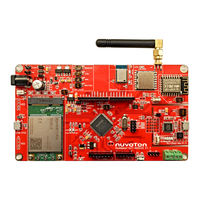
Nuvoton NuMicro NuMaker-IoT-M263A User Manual (50 pages)
Brand:
Nuvoton
| Category:
Microcontrollers
| Size: 3 MB
Table of Contents
Table of Contents
2
1 Overview
7
Figure 1-1 Numaker-Iot-M263A Board
7
Numaker-Iot-M263A Features
8
2 Numaker-Iot-M263A Overview
9
Figure 2-1 Front View of Numaker-Iot-M263A
9
Front View
9
Figure 2-2 Rear View of Numaker-Iot-M263A
11
Arduino uno Compatible Extension Connectors
12
Figure 2-3 Arduino uno Compatible Extension Connectors
12
Table 2-1 Arduino uno Extension Connectors and M263KIAAE Mapping GPIO List
13
Pin Assignment for On-Board Modules, Sensors and Connectors
14
Table 2-2 On-Board Modules, Sensors, Connectors and M263KIAAE GPIO Function List
15
Power Sources
16
System Configuration
16
Table 2-3 VIN Power Source
16
Table 2-4 5V Power Sources
16
VIN Power Source
16
Power Connectors
17
Power Sources
17
Table 2-5 3.3 V Power Sources
17
Table 2-6 1.8V Power Sources
17
Table 2-7 Power Connectors
17
Table 2-8 USB Connectors
17
USB Connectors
17
CAN Connectors
18
Power Switches
18
RS485 Connectors
18
Table 2-10 RS485 Connectors
18
Table 2-11 Power Switches
18
Table 2-9 CAN Connectors
18
2.5.10 Target Chip Power Supply Models
19
Figure 2-4 External Power Supply Sources on Nu-Link2-Me
19
Table 2-12 Supply External Power through Nu-Link2-Me
19
Figure 2-5 External Power Supply Sources on M263 Platform
20
Figure 2-6 Separate the Nu-Link2-Me from Numaker-Iot-M263A
21
Table 2-13 Supply External Power for M263 Platform
21
2.5.11 On-Board Module Power Supply Models
22
Figure 2-7 External Power Supply Sources on Numaker-Iot-M263A for On-Board Modules
22
Table 2-14 Supply External Power for On-Board Modules
22
2.5.12 Mini Pcie Connector Power Supply Models
23
Figure 2-8 External Power Supply Sources on Numaker-Iot-M263A for Mini Pcie Connector
23
Table 2-15 Supply External Power through Numaker-Iot-M263A
23
2.5.13 External Reference Voltage Connector
24
2.5.14 Ammeter Connector
24
2.5.15 Wi-Fi Module Update Switch
24
Figure 2-9 Wiring between Ammeter Connector and Ammeter
24
Table 2-16 External Reference Voltage Connector
24
Table 2-17 Ammeter Connector
24
Table 2-18 Wi-Fi Module Update Switch
24
2.5.16 Extension Connectors
25
2.5.17 Push-Buttons
25
2.5.18 Leds
25
Table 2-19 Extension Connectors
25
Table 2-20 Push-Buttons
25
Table 2-21 Leds
25
Rear View
11
Nu-Link2-Me
26
Table 2-22 VCOM Function of Nu-Link2-Me
26
Figure 2-10 Front Placement
27
Figure 2-11 Rear Placement
27
PCB Placement
27
Toolchains Support
28
Figure 3-1 Nu-Link USB Driver Installation Setup
28
Nuvoton Nu-Link Driver Installation
28
Figure 3-2 Nu-Link USB Driver Installation
29
BSP Firmware Download
30
Figure 3-3 Open VCOM Function
30
Figure 3-4 ICE USB Connector
30
Hardware Setup
30
Figure 3-5 Device Manger
31
Figure 3-6 Putty Session Setting
31
Execute the Project under Toolchains
32
Figure 3-7 Template Project Folder Path
32
Figure 3-8 Warning Message "Device Not Found
32
Find the Example Project
32
Keil MDK
32
Figure 3-10 Debugger Setting in Options Window
33
Figure 3-9 Project File Migrate to Version 5 Format
33
Figure 3-11 Programming Setting in Options Window
34
Figure 3-12 Compile and Download the Project
34
Figure 3-13 Keil MDK Debug Mode
35
Figure 3-14 Debug Message on Serial Port Terminal Windows
35
Figure 3-15 IAR EWARM Window
36
Figure 3-16 Compile and Download the Project
36
Iar Ewarm
36
Figure 3-17 IAR EWARM Debug Mode
37
Figure 3-18 Debug Message on Serial Port Terminal Windows
37
Nueclipse
37
3 Quick Start
28
Figure 4-1 Nu-Link2-Me Circuit
38
M263 Platform
39
Figure 4-2 M263 Platform Circuit
39
Extension Connector
40
Figure 4-3 Extension Connectors Circuit
40
Mini Pcie Connector
41
Figure 4-4 Mini Pcie Connector Circuit
41
Figure 4-5 On-Board Bluetooth Module Circuit
42
On-Board Bluetooth Module
42
Figure 4-6 On-Board Wi-Fi Module Circuit
43
On-Board Wi-Fi Module
43
Figure 4-7 On-Board Lora Module Circuit
44
On-Board Lora Module
44
On-Board Sensors
45
Figure 4-8 On-Board Sensors Circuit
45
CAN and RS485 Connector
46
Figure 4-9 CAN and RS485 Connector Circuit
46
Figure 4-10 Microsd Card Connector Circuit
47
Microsd Card Connector
47
Figure 4-11 On-Board Modules and Mini Pcie Connector Power Circuit
48
On-Board Modules and Mini Pcie Connector Power
48
4 Numaker-Iot-M263A Schematics
38
5 Revision History
49
Nu-Link2-Me
38
Advertisement
Advertisement
Related Products
Nuvoton NuMicro NuMaker-M032KG
Nuvoton NuMicro NuMaker-M032KI
Nuvoton NuMicro NuMaker-M483KG
Nuvoton NuMaker-M252KG
Nuvoton ARM NuMaker-emWin-RDK-N9H20
Nuvoton NuMicro NuMaker-PFM-M487KM
Nuvoton NuMicro NuMaker-M031KG
Nuvoton NuMaker-Volcano
Nuvoton Numicro NuMaker-NUC1311L
Nuvoton NuMicro NuMaker-HMI-M2354
Nuvoton Categories
Motherboard
Microcontrollers
Computer Hardware
Amplifier
Controller
More Nuvoton Manuals
Login
Sign In
OR
Sign in with Facebook
Sign in with Google
Upload manual
Upload from disk
Upload from URL