Sign In
Upload
Manuals
Brands
Nordson Manuals
Industrial Equipment
PURBlue EC
Nordson PURBlue EC Manuals
Manuals and User Guides for Nordson PURBlue EC. We have
1
Nordson PURBlue EC manual available for free PDF download: Manual
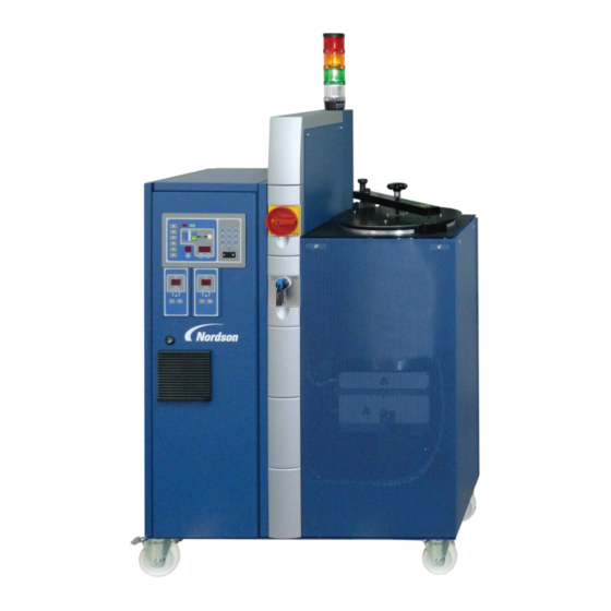
Nordson PURBlue EC Manual (182 pages)
Adhesive Melters
Brand:
Nordson
| Category:
Industrial Equipment
| Size: 2.91 MB
Table of Contents
Table of Contents
3
Nordson International
11
Europe
11
Distributors in Eastern & Southern Europe
11
Outside Europe / Hors D'europe / Fuera de Europa
12
Africa / Middle East
12
Asia / Australia / Latin America
12
Japan
12
North America
12
Safety
13
Safety Alert Symbols
13
Responsibilities of the Equipment Owner
14
Safety Information
14
Instructions, Requirements, and Standards
14
User Qualifications
15
Applicable Industry Safety Practices
16
Intended Use of the Equipment
16
Instructions and Safety Messages
16
Installation Practices
17
Operating Practices
17
Maintenance and Repair Practices
18
Equipment Safety Information
19
Equipment Shutdown
19
Relieving System Hydraulic Pressure
19
De-Energizing the System
19
Disabling the Guns
20
General Safety Warnings and Cautions
21
Other Safety Precautions
24
First Aid
24
Introduction
25
Intended Use
25
Area of Use (EMC)
25
Operating Restrictions
25
Unintended Use − Examples
25
Residual Risks
26
Definition of Terms
26
Inert Gas
26
Key-To-Line
26
Melter Description
27
Illustration − Exterior
27
Illustration − Interior Components
28
Tank Isolation Valve
28
Safety Valve Plate
29
Safety Valve
29
Pressure Control Valve
29
Plug
29
Heating Plate
29
Tank
30
Cable Glands
30
Melter Inputs/Outputs
30
Electrical Cabinet
31
ID Plate
32
Installation
33
Transport
33
Storage
33
Unpacking
33
Lifting (Unpacked Melter)
34
Installation Requirements
34
Required Space
34
Exhausting Material Vapors
35
Installation Personnel's Experience
35
Electrical Connections
36
General Notes
36
Observe When Using Residual Current Circuit Breakers
36
Laying Cable
36
Operating Voltage
36
External Control/Signal Circuits
37
Power Supply Connection
37
Setting Timer Relay (Inert Gas Interval)
38
Installing Melter Inputs and Outputs
39
Information on I/O Expansion Board
41
Standard Inputs
41
Standard Outputs
43
Connecting Hose
44
Connecting Electrically
44
Connecting
44
Second Open-Jawed Wrench
44
Disconnecting
45
Relieving Pressure
45
Connecting Inert Gas
46
Installing Gun
47
Conditioning Compressed Air for Gun Control Modules
47
Removing Melter
47
Disposing of Melter
47
Operation
49
Modes
49
Initial Startup
50
Purging Melter
50
Filling the Tank
52
Maximum Level
52
Setting up the Melter
53
Control Panel − Overview
53
Setting Operating Parameters
54
Helpful Information
55
Saving and Restoring Settings
56
Saving All Current Settings
56
Restoring Saved Settings
56
Saving Multiple Variations of Melter Settings
56
Daily Startup
57
Daily Switchoff
58
Switching off in an Emergency
58
Monitoring Aids
59
LED Ready
59
LED Fault
59
LED Service Required (Wrench Symbol)
59
Resetting Service LED
59
LED Pump
59
Change History Log
60
Calling up Change History Log
60
Structure of Change History Log
61
Example 1 − Parameter Changed
61
Example 2 − Setpoint Temperature Changed
61
Example 3 − Empty Log Entry
61
Entering Password
62
Heated Components
63
Meaning of LED Colors of Component Keys
63
Setpoint Temperature (Original State)
63
Adjusting Setpoint Temperatures
64
Adjusting Temperatures Using the Global Method
64
Switching off All Components
64
Adjusting Temperatures Using the Global-By-Component Group Method
65
Adjusting Temperature of an Individual Component
66
Switching off Component
66
Quick Adjustment − Tips
67
Helpful Information
67
Checking Temperatures
68
Checking Actual Temperature in Normal Mode
68
Checking Setpoint Temperature in Normal Mode
68
Checking Actual Temperature Manually
69
Functions and Function Keys
70
Standby
70
Manual Entry/Exit with the Key
70
Automatic Exit Via Parameter 26
70
Automatic Entry/Exit Via the Seven-Day Clock
70
Automatic Entry Via External Input 1
71
Entry/Exit Via External Input 1 − 4
71
Helpful Information
71
Pump
71
Heater
71
Seven-Day Clock
72
Bypassing the Seven-Day Clock
72
Setup
72
Controls Pump Speed and Purge Mode
73
Setting Speed (RPM)
73
Pump Speed Display
73
Mode Switch
73
Purging
74
Operating Parameter 8 (Automatic Pump On) Enabled − Original State
74
Operating Parameter 8 (Automatic Pump On) Disabled
74
Switching on Pump Via the Control Option
74
Enable/Disable Motor (External Motor Enable)
74
Important When Changing Material
75
Communication Via Serial Interface
75
Settings Record
76
Maintenance
77
Notes on Cardan Joint
78
Preventive Maintenance
79
External Cleaning
80
Purging with Cleaning Agent
81
Fan and Air Filter
82
Motor / Gear Box
84
Important for Mechanical Pressure Control Valve
86
Cleaning Tank by Hand
87
Safety Valve Plate
88
Replacing Plug (O-Ring)
89
Pneumatic Safety Valve
92
Maintenance Record Form
93
Troubleshooting
95
Fault Numbers
96
F1, F2 and F3 Faults
97
F4 Fault
98
Resetting Melter
99
Structure of Fault Log
100
Board Overview
101
Leds and Fuses on Main Board
102
Troubleshooting Tables
103
Control Panel Does Not Function
104
No Material (Motor Does Not Rotate)
105
Material Pressure too High
107
Others
108
Repair
109
Notes on Cardan Joint
110
Replacing Pump
111
Detaching Pump
112
Replacing Motor
113
Replacing Safety Valve
115
Replacing Motor Controller
116
Observe When Performing Work Behind Electrical Equipment Covers
117
Replacing Heater Cartridges
118
Reservoir
119
Band Heater
120
Replacing Control Panel (Service Kit)
121
Parts
123
How to Use Illustrated Parts List
123
Component Designation
123
Assembly Overview
124
Spare Parts, Service Kits and Accessories
127
Safety Valve
127
Gear Pump
128
Pressure Control Valve
129
Inert Gas Equipment
130
Manifold
132
Manifold Accessories
133
Bypass Plate
134
Heating Plate
135
Ship-With-Kit
136
Electrical Components
137
Additional Service Kits
140
Fuses Main Board
140
Main Board
141
Front Panel
142
CPU Board
142
RTD Sensor
142
Temperature Switches (Thermostats)
142
Panel Latch
143
By-Pack Frequency Converter
143
Additional Accessory Kits
144
Casters
144
Accessories for Pneumatic Connection by the Customer
144
Technical Data
145
General Data
145
Temperatures
146
Electrical Data
146
Mechanical Data
146
Options
147
Casters
147
Installing Kit (Accessory)
147
General Instructions Regarding Working with
149
Application Materials
149
Definition of Terms
149
Manufacturer Information
149
Liability
149
Risk of Burns
149
Vapors and Gases
150
Substrate
150
Processing Temperature
150
Important Note for Polyurethane Materials (PUR
150
Operating Parameters
151
Parameter Groups - Overview
151
Restore Melter Default Settings
151
Original State
151
Standard
152
Input Setup
161
Standard Inputs
161
Optional Inputs
163
Output Setup
164
Standard Outputs
164
Optional Outputs
165
Seven-Day Clock
166
Setting Internal Clock (Realtime Clock
166
Creating Schedule
166
Example 1
172
Example 2
172
Example 3
172
Timer for Automatic Filling
173
Output (Control Option 3): Reversal of Fault Logic
173
PID Selection
173
Melter Communication
175
Software Availability
175
System Requirements
175
Installing the Software
176
Removing the Software from Your PC
177
Linking PC and Melter
177
Using Nordson Configuration Manager
178
Saving Melter Settings
178
Restoring Melter Settings
179
Upgrading or Restoring Melter Firmware
180
Troubleshooting
182
Advertisement
Advertisement
Related Products
Nordson PURBlue 4
Nordson Prodigy HDLV Pump Generation II
Nordson ProBlue Fulfill
Nordson PRODIGY
Nordson Prodigy HDLV
Nordson ProBlue P4
Nordson ProBlue P7
Nordson PCI
Nordson ProBlue Flex
Nordson PatternCoat Series
Nordson Categories
Paint Sprayer
Industrial Equipment
Dispenser
Water Pump
Controller
More Nordson Manuals
Login
Sign In
OR
Sign in with Facebook
Sign in with Google
Upload manual
Upload from disk
Upload from URL