Sign In
Upload
Manuals
Brands
Nonin Manuals
Measuring Instruments
SenSmart X-100
Nonin SenSmart X-100 Manuals
Manuals and User Guides for Nonin SenSmart X-100. We have
2
Nonin SenSmart X-100 manuals available for free PDF download: Operator's Manual, Service Training
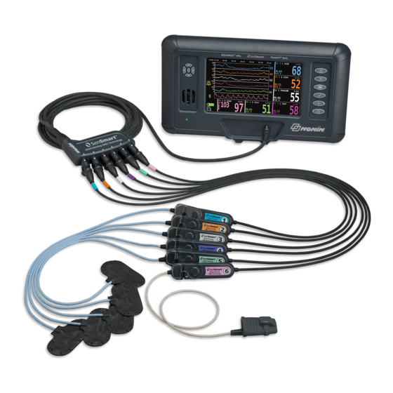
Nonin SenSmart X-100 Operator's Manual (107 pages)
Universal Oximetry System
Brand:
Nonin
| Category:
Measuring Instruments
| Size: 4 MB
Table of Contents
Table of Contents
3
Indications for Use
9
Contraindications
9
Warnings
9
Cautions
11
Declaration of Conformity with FCC and Canadian Ministry of Health Rules for Electromagnetic Compatibility
13
Federal Communications Commission (FCC) Notice
13
Table 1. Labeling and Packaging Symbols
14
Guide to Symbols
14
Figure 1. Monitoring Screen Symbols (Four-Channel View)
16
Table 2. X-100M Monitoring Screen Symbols and Indicators
16
System Components and Set up
20
System Configurations
20
Multiple Channels
20
Figure 2. System Set up (≥40 Kg Sensors, INT-100, 4 Channels Connected)
21
Figure 3. System Set up (≤40 Kg Sensors, 4 Channels Connected)
21
Single Channel
22
Figure 4. System Set up (≥40 Kg Sensors, 4 Channels Connected)
22
Figure 5. System Set up (≥40 Kg Sensor, INT-100, Single Channel)
22
X-100M (Monitor)
23
Figure 6. X-100M Front View
23
Table 3. X-100M Features
23
X-100H (Hub)
26
Connect/Disconnect the Hub
26
Figure 7. X-100H - Hub
26
Figure 8. Connect Hub or Signal Processor to Monitor
26
Table 4. X-100H Features
26
X-100HH (Hub Holster)
27
Using the Hub Holster
27
Figure 9. X-100HH - Hub Holster
27
Figure 10. Insert Hub into Hub Holster
27
Table 5. X-100HH Features
27
X-100SP (Signal Processor)
28
Connect a Signal Processor to Hub or Monitor
28
Disconnect a Signal Processor from Hub or Monitor
28
Figure 11. X-100SP - Signal Processor
28
Table 6. X-100SP Features
28
Connect/Disconnect an INT-100 Intermediate Cable to the Signal Processor
29
Connect/Disconnect a Sensor to the Signal Processor
29
Figure 12. Connect Intermediate Cable or Sensor to Signal Processor
29
Replacing the Lock on the Signal Processor
30
Cable Clips
30
Intermediate Cable)
30
Figure 13. Signal Processor Lock Replacement
30
Figure 14. INT-100 - Intermediate Cable
30
Table 7. INT-100 Features
30
Connect/Disconnect a Sensor to the Intermediate Cable
31
X-100EC (Extension Cable)
31
Figure 15. Connect Sensor to Intermediate Cable
31
Figure 16. X-100EC - Extension Cable
31
Rso 2 and Spo 2 Sensors
32
Battery
32
System Operation
33
Start-Up Sequence
33
Figure 17. Start-Up Screen
33
Figure 18. Select a Preset Screen
33
Sensor Application
34
Monitoring a Patient
34
Operating Screens and Menus
35
Monitoring Screen
36
Monitoring Screen - Description
36
Channels
36
Figure 19. Monitoring Screen with Four Channels Connected (3 Rso 2 and 1 Spo 2 )
36
Event Marks
37
Event Mark Table
37
Timescale
37
Figure 20. Event Marks, Timescale, and Scrolling Cursor
37
Figure 21. Event Mark Table
37
Scrolling Cursor and Cursor Values
38
Graphs
38
Figure 22. Graphs
38
Monitoring Screen - Procedures
39
Set All Rso Channel Baselines to Current %Rso Values
39
Mark an Event
39
View the Event Mark Table
39
Change the Timescale
39
Scroll through the Timescale
39
Graph Set-Up
39
Settings Menu Screen
40
Settings Menu - Description
40
Sensor Site
40
Figure 23. Settings Menu Screen
40
Sensor Type
41
Baseline (Rso 2 Channels Only)
41
Table 8. Commonly-Used Sensor Site Names
41
Alarm Limits
42
Table 9. Alarm Limit Settings
42
Graph Position
43
Preset
43
Settings Menu - Procedures
44
Open the Settings Menu
44
Assign a Pre-Defined Sensor Site Name
44
Customize a Sensor Site Name
44
Clear a Sensor Site Name
44
Set Sensor Type
45
Set Individual Baseline Values
45
Set Alarm Limits
46
Set Graph Position(S)
46
Review/Select a Preset
46
Presets Menu Screen
47
Presets Menu - Description
47
Presets Menu - Procedures
48
Open the Presets Menu
48
Activate a Preset
48
Save Current Settings as a Preset
48
Figure 24. Presets Menu Screen
48
Delete a Preset
49
Rename a Preset
49
Lock/Unlock a Preset
50
Case Menu Screen
51
Case Menu - Description
51
Start New Case
51
Edit Patient ID
51
Case Menu - Procedures
51
Open the Case Menu
51
Figure 25. Case Menu Screen
51
Start a New Case
52
Edit a Patient ID
52
System Menu Screen
53
System Menu - Description
53
Figure 26. System Menu Screen
53
Alarm Volume
54
Brightness
54
Pulse Tone Volume
54
Rso 2 Low Alarm Mode
54
Clear Memory
55
Data Output Modes
55
Pulse Tone Source
55
Restore Factory Defaults
55
System Information
55
Table 10. Factory Default Alarm Limit Settings
55
Date / Time
56
Figure 27. System Information Pop-Up
56
Nurse Call Mode
56
Bluetooth
57
Figure 28. Bluetooth Information Pop-Up
57
Language
57
Default Preset
58
Institution Default Limits
58
Patient ID Request
58
System Name
58
Institution Password
59
System Menu - Procedures
59
Open the System Menu
59
Adjust the Display Brightness
59
Figure 29. Institution Defaults Pop-Up
59
Adjust the Alarm Volume
60
Set the Rso 2 Low Alarm Mode
60
Adjust the Pulse Tone Volume
60
Select a Pulse Tone Source
61
Set Bluetooth And/Or RS-232 Data Output Formats
61
Clear the Memory
61
Restore Factory Defaults
62
Review System Information
62
Set the Date and Time
62
Set-Up Nurse Call
62
Enable/Disable Bluetooth Radio
63
Change Language
63
Set Patient ID Request
63
Assign System Name
64
Select Default Preset
64
Set Institution Default Limits
65
Change the Institution Password
65
Alarms
66
High Priority Alarms
66
Table 11. High Priority Alarms
66
Medium Priority Alarms
67
Silencing Alarms
67
Table 12. Medium Priority Alarms
67
Error Codes
68
Table 13. Error Codes
68
Memory and Data Output Features
69
Memory
69
Patient Data Output
69
Figure 30. RS-232 Serial Data Port
69
Bluetooth Connection
70
Determine the Bluetooth Address and PIN for the Monitor
70
Bluetooth Technology
70
Bluetooth Security
71
RS-232 Connection to Printer
71
Using the Dymo Printer
71
Figure 31. Sample Label from Dymo Printer
71
Connecting the Device into a Medical System
72
Data Output Formats
72
Nonin 1
73
Table 14. Nonin 1 Data Output Format
73
Nonin 2
76
Nonin 3
77
Nonin 4
78
Nonin 5
79
Printer
80
Sensmart Download Software
81
System Requirements
81
Installing Sensmart Download Software
81
Care and Maintenance
82
Cleaning Instructions
82
Parts and Accessories
83
Troubleshooting
84
Service, Support, and Warranty
87
Service and Support
87
Warranty
87
Technical Information
89
Manufacturer's Declaration
89
Table 15. Electromagnetic Emissions
89
Table 16. Electromagnetic Immunity
90
Table 17. Guidance and Manufacturer's Declaration-Electromagnetic Immunity
91
Table 18. Recommended Separation Distances
92
Equipment Response Time
93
Example - Spo Exponential Averaging
93
Testing Summary
94
Rso 2 Principles of Operation
94
Spo 2 Principles of Operation
94
Rso 2 Accuracy Testing
94
Spo 2 Accuracy Testing
95
Pulse Rate Accuracy Testing (Motion and Non-Motion)
95
Low Perfusion Accuracy Testing
95
Specifications
96
Transmitter
98
External Monitor Installation Instructions
99
Philips Monitors
99
Components
99
Vuelink Components
99
Intellibridge Components
99
Connection Specifications
99
Connecting the X-100M Monitor to the Philips Monitor
100
X-100M Configuration
100
Philips Interface Module Installation and Configuration
100
Setting up the Connection - Vuelink
100
Figure 32. X-100M Connection to Philips Monitor with Vuelink
101
Figure 33. Philips Indicator on Model X-100M Display
101
Setting up the Connection - Intellibridge
102
Figure 34. X-100M Connection to Philips Monitor with Intellibridge
102
Philips Monitor Display Configuration
103
Setup Philips Monitor with Vuelink Interface Module to Display X-100M Numerics
103
Setup Philips Monitor with Intellibridge Interface Module to Display X-100M Numerics
104
Alerts
105
Patient Alarms
106
Table 19. Philips Monitor Patient Alarms
106
Equipment Alarms
107
Table 20. Philips Monitor Equipment Alarms
107
Advertisement
Nonin SenSmart X-100 Service Training (34 pages)
Universal Oximetry System In-Service Training
Brand:
Nonin
| Category:
Medical Equipment
| Size: 3 MB
Table of Contents
Table of Contents
2
Introduction
4
Indications for Use
5
Theory of Operation
5
What Is Rso
5
Reusable Pulse Oximetry (Spo 2 ) Sensor Application
5
What Is %Spo
6
System Components
7
System Setup
8
X-100H Hub
8
Connect/Disconnect the Hub to the Monitor
8
X-100HH Hub Holster
8
X-100SP Signal Processors
9
Connect/Disconnect a Signal Processor
10
System Sensors
10
Connect/Disconnect a Sensor To/From the Signal Processor
10
Rso Sensors
10
Rso 2 Sensor Application
11
Spo 2 Sensors
12
X-100EC Extension Cables
13
System Power On/Off
13
Review of the Model X-100 Universal Oximetry System Setup
14
Monitor Features
15
Controls and Navigation
16
System Display
18
System Configuration Screens and Menus
20
Settings Menu
20
Sensor Site
21
Sensor Type
21
Baseline (Manual Setting)
21
Setting High and Low Alarm Limits for Rso or Spo
22
Graph Position
22
Review Current Preset
23
Presets Menu
23
Case Menu
24
System Menu
25
Review System Menus
27
System Alarm Indicators
28
High Priority Alarms
28
Medium Priority Alarms
28
Troubleshooting
29
System Memory
31
System Data Outputs
31
Cleaning the System Components
32
Warranty
33
How to Get Help - Service and Support
33
Customer and Technical Service Contact Information
33
Advertisement
Related Products
Nonin Sensmart H500
Nonin 7600
Nonin Categories
Medical Equipment
Measuring Instruments
Personal Care Products
Accessories
Pet Care Product
More Nonin Manuals
Login
Sign In
OR
Sign in with Facebook
Sign in with Google
Upload manual
Upload from disk
Upload from URL