Table of Contents
Advertisement
Quick Links
Download this manual
See also:
Service Training
Advertisement
Table of Contents

Subscribe to Our Youtube Channel
Related Manuals for Nonin SenSmart X-100


Summary of Contents for Nonin SenSmart X-100
- Page 1 Operator’s Manual Model X-100 Universal Oximetry System English 0123...
- Page 2 Nonin Medical, Inc. The Bluetooth word mark and logos are owned by the Bluetooth SIG, Inc. and any use of such marks by Nonin Medical, Inc. is under license. Other trademarks and trade names are those of their respective owners.
-
Page 3: Table Of Contents
Contents Indications for Use ....................1 Contraindications ........................ 1 Warnings ..........................1 Cautions ..........................3 Declaration of Conformity with FCC and Canadian Ministry of Health Rules for Electromagnetic Compatibility ..................5 Federal Communications Commission (FCC) Notice ............5 Guide to Symbols..................... 6 System Components and Set Up................ - Page 4 Contents (Continued) Scroll Through the Timescale ..................31 Graph Set-up ........................ 31 Settings Menu Screen .................... 32 Settings Menu – Description..................... 32 Sensor Site ........................32 Sensor Type ........................ 33 Baseline (rSO channels only)..................33 Alarm Limits ........................34 Graph Position ......................35 Preset #: ........................
- Page 5 RS-232 Connection to Printer ..................63 Using the Dymo Printer ....................63 Connecting the Device into a Medical System ..............64 Data Output Formats......................64 Nonin 1 .......................... 65 Nonin 2 .......................... 68 Nonin 3 .......................... 69 Nonin 4 .......................... 70...
- Page 6 Contents (Continued) Nonin 5 ......................... 71 Printer ........................... 72 SenSmart Download Software................73 System Requirements ...................... 73 Installing SenSmart Download Software ................73 Care and Maintenance.................... 74 Cleaning Instructions ......................74 Parts and Accessories ................... 75 Troubleshooting...................... 76 Service, Support, and Warranty ................79 Service and Support ......................
- Page 7 Figures Figure 1. Monitoring Screen Symbols (Four-Channel View)..............8 Figure 2. System Set Up (≥40 kg Sensors, INT-100, 4 Channels Connected)........13 Figure 3. System Set Up (≤40 kg Sensors, 4 Channels Connected)..........13 Figure 4. System Set Up (≥40 kg Sensors, 4 Channels Connected)..........14 Figure 5.
- Page 8 Table 11. High Priority Alarms......................58 Table 12. Medium Priority Alarms ..................... 59 Table 13. Error Codes ........................60 Table 14. Nonin 1 Data Output Format ..................... 65 Table 15. Electromagnetic Emissions ....................81 Table 16. Electromagnetic Immunity ....................82 Table 17.
-
Page 9: Indications For Use
Indications for Use Indications for Use Nonin’s SenSmart™ Model X-100 Universal Oximetry System is a modular system and is indicated for use in simultaneously measuring, displaying, monitoring, and recording up to six (6) channels of functional oxygen saturation of arterial hemoglobin (SpO... - Page 10 Indications for Use Warnings (Continued) As with all medical equipment, carefully route patient cables and connections to reduce the possibility of entanglement, strangulation, or tripping. For remote monitoring, use the X-100M monitor only within its designated range (approximately 100 meters (300 feet) spherical radius from monitor to remote location).
-
Page 11: Cautions
Do not autoclave, sterilize, immerse, or spray this device with liquid or use caustic or abrasive cleaning agents. Do not use cleaning agents or cleaning products that contain ammonium chloride. Follow local, state and national governing ordinances and recycling instructions regarding disposal or recycling of the device and device components, including batteries. Use only Nonin-approved battery packs. - Page 12 If you are unsure how to reach your distributor, please call Nonin for your distributor’s contact information. Data is written continuously to memory when the device is on. If the entire memory is filled, portions of the oldest record will be overwritten when new data is written.
-
Page 13: Declaration Of Conformity With Fcc And Canadian Ministry Of Health Rules For Electromagnetic Compatibility
C95.1-2005. The FCC requires the user to be notified that any changes or modifications to this device that are not expressly approved by Nonin Medical, Inc. may void the user’s authority to operate the equipment. NOTE: No modifications to this device are allowed that in any way affect or alter its antenna... -
Page 14: Guide To Symbols
Guide to Symbols Guide to Symbols This chapter describes the symbols that are found on the Model X-100 system components and packaging. Detailed information about functional symbols can be found in "System Components and Set Up" on page 12. Table 1. Labeling and Packaging Symbols Symbol Description CAUTION! - Page 15 Guide to Symbols Table 1. Labeling and Packaging Symbols (Continued) Symbol Description Do not discard. Do not pull on cable. Retract connector and remove. Lot Number Catalogue number Quantity Date of manufacture Manufacturer Non-sterile STERILE STERILE Storage/shipping temperature range Handle with care. Keep dry.
-
Page 16: Figure 1. Monitoring Screen Symbols (Four-Channel View)
Guide to Symbols Figure 1. Monitoring Screen Symbols (Four-Channel View) Table 2. X-100M Monitoring Screen Symbols and Indicators Symbol Description Event Marks example: Located at the top of the monitoring screen, event marks (A, B, C, D, etc.) display when the Event Mark button is pressed. Timescale example: Located below the event marks, the timescale shows the amount of data... - Page 17 Guide to Symbols Table 2. X-100M Monitoring Screen Symbols and Indicators (Continued) Symbol Description Channel Located at the top of each channel, this indicator shows the channel’s number (e.g., Ch 1, Ch 2, etc.). If set, the sensor site name displays to the right of the channel indicator.
- Page 18 Guide to Symbols Table 2. X-100M Monitoring Screen Symbols and Indicators (Continued) Symbol Description Low Alarm Limit example: The low alarm limit is determined by the %rSO Low setting and displays as the following: • Numeric value – This value displays to the right of a trendline graph. The color of the value matches the color of the associated channel.
- Page 19 Guide to Symbols Table 2. X-100M Monitoring Screen Symbols and Indicators (Continued) Symbol Description Alarm Silence This yellow indicator flashes once every 2 seconds when the audible alarm is silenced for 2 minutes. If the alarm volume is at step 4 or lower (less than 45 decibels), the Alarm Silence indicator is solidly lit.
-
Page 20: System Components And Set Up
System Components and Set Up System Components and Set Up NOTES: • Before using the SenSmart system, please review all contraindications, warnings, and cautions. • Before using the Model X-100M for the first time, the battery should be charged for 4 hours. •... -
Page 21: Figure 2. System Set Up (≥40 Kg Sensors, Int-100, 4 Channels Connected)
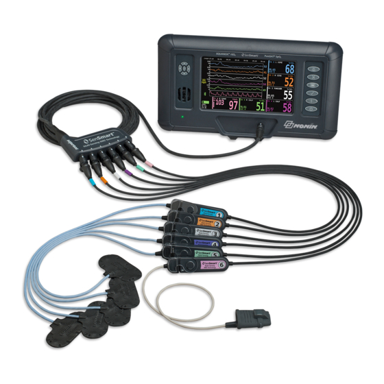
System Components and Set Up X-100M X-100H X-100SP INT-100 Sensors Figure 2. System Set Up (≥40 kg Sensors, INT-100, 4 Channels Connected) X-100M X-100H X-100SP Sensors Figure 3. System Set Up (≤40 kg Sensors, 4 Channels Connected) -
Page 22: Single Channel
System Components and Set Up X-100M X-100H X-100SP Sensors Figure 4. System Set Up (≥40 kg Sensors, 4 Channels Connected) Single Channel When using a single channel (figure 5), the signal processor can be connected directly to the monitor. If needed, an extension cable can be used between the monitor and the signal processor. -
Page 23: X-100M (Monitor)
System Components and Set Up X-100M (Monitor) The X-100M monitor (figure 6) allows the user to view up to six channels of rSO and SpO data. Each channel is color coded and numbered to match a signal processor. See table 3 for monitor features and descriptions. - Page 24 System Components and Set Up Table 3. X-100M Features (Continued) Symbol Description Menu Button Pressing this button opens the Settings menu and allows access to the Presets, Case, and System menus: • Settings – allows users to assign a sensor site name to a channel, select sensor type (rSO or SpO ), set limits and graphs, and review...
- Page 25 System Components and Set Up Table 3. X-100M Features (Continued) Symbol Description Navigation Buttons These buttons are used to navigate between fields, scroll, and change the timescale. (Up) and (Down): In menus, used to navigate between items. On the monitoring screen, used to change the rSO trendline timescale.
-
Page 26: X-100H (Hub)
System Components and Set Up X-100H (Hub) The X-100H hub (figure 7) connects to the connector port on the front of the monitor. The hub provides connections for up to six X-100SP signal processors via the hub ports. Each hub port has a protective port cover. -
Page 27: X-100Hh (Hub Holster)
System Components and Set Up X-100HH (Hub Holster) The hub fits inside the X-100HH hub holster (figure 9). The hub holster clamp allows the hub to be attached to bed rails, equipment poles, and linen. Using the Hub Holster 1. To insert the hub: Figure 9. -
Page 28: X-100Sp (Signal Processor)
System Components and Set Up X-100SP (Signal Processor) Up to six signal processors can be connected to the hub. Each signal processor is programmed to be a specific channel on the monitor, so a signal processor may be connected to any hub port. -
Page 29: Connect/Disconnect An Int-100 Intermediate Cable To The Signal Processor
System Components and Set Up Connect/Disconnect an INT-100 Intermediate Cable to the Signal Processor NOTE: The INT-100 is used to connect the 8204CA (patients ≥40 kg) sensor to the signal processor. 1. To connect: a. Flip the clear lock on the signal processor back to expose the connection port. b. -
Page 30: Replacing The Lock On The Signal Processor
System Components and Set Up Replacing the Lock on the Signal Processor NOTE: Replacement locks may be ordered if the lock is lost or damaged. 1. Align the lock hinge with the connector end of the signal processor (figure 13-A). 2. -
Page 31: Connect/Disconnect A Sensor To The Intermediate Cable
System Components and Set Up Connect/Disconnect a Sensor to the Intermediate Cable NOTE: The INT-100 is used to connect the 8204CA (patients ≥40 kg) sensor to the signal processor. 1. To connect: a. Slide the sensor lock on the INT-100 away from the port. b. -
Page 32: Rso 2 And Spo 2 Sensors
• Follow local, state and national governing ordinances and recycling instructions regarding disposal or recycling of the device and device components, including batteries. • Use only Nonin-approved battery packs. • Batteries are a fire hazard if damaged. Do not damage, mishandle, disassemble, service, or replace with non-specified components. -
Page 33: System Operation
Nonin logo (figure 17). 3. An audible tone sounds. Verify each of the above items occur on initialization. If any do not occur, contact Nonin Technical Service for assistance. Figure 17. Start-up Screen Following the start-up sequence, the monitor displays the Select a Preset screen (figure 18). -
Page 34: Sensor Application
System Operation Sensor Application Refer to the sensor instructions for use for proper sensor application sites and sensor application cautions and warnings. WARNING: This device is intended only as an adjunct device in patient assessment. It should not be used as the sole basis for diagnosis or therapy decisions. It must be used in conjunction with other methods of assessing clinical signs and symptoms. -
Page 35: Operating Screens And Menus
System Operation Operating Screens and Menus The X-100M monitoring screen can be configured to display up to six channels of rSO data, along with rSO trendlines and SpO plethysmograms. See “Monitoring Screen” on page 28 for more information. The operating menus display when the Menu button is pressed. The Settings Menu screen opens and additional menu tabs for Presets, Case, and System display across the top of the screen. -
Page 36: Monitoring Screen
Monitoring Screen Monitoring Screen This section contains: • Description of the monitoring screen features • Monitoring screen procedures (see page 31) Monitoring Screen – Description Channels When up to four channels are monitoring, real-time numeric data displays by channel on the right side of the screen. -
Page 37: Event Marks
Monitoring Screen Event Marks Event marks are located at the top of the monitoring screen above the timescale (figure 20). When pressed, the Event Mark button places a mark above the displayed graphs, in the memory, and in the real-time serial data output. Events are marked with increasing alphabetic letters. -
Page 38: Scrolling Cursor And Cursor Values
Monitoring Screen Scrolling Cursor and Cursor Values The scrolling cursor and the cursor values display when the Left navigation button is pressed. The scrolling cursor displays directly below the timescale and moves back and forth across the top of the channel graph display area (figure 20). Use the Left and Right navigation buttons to move the cursor. -
Page 39: Monitoring Screen - Procedures
Monitoring Screen Monitoring Screen – Procedures Set All rSO Channel Baselines to Current %rSO Values 1. (OPTIONAL STEP) Press Event Mark to mark an event. Record the letter of the event in the hospital records. 2. While in the monitoring screen, press Baseline. “Update baselines for rSO channels”... -
Page 40: Settings Menu Screen
Settings Menu Screen Settings Menu Screen This section contains: • Description of the Settings Menu • Settings Menu procedures (see page 36) Settings Menu – Description The Settings screen allows the user to configure the system for specific use case needs. From the Settings screen, the user can review and configure the following settings and alarm limits. -
Page 41: Sensor Type
Settings Menu Screen Table 8. Commonly-Used Sensor Site Names Head Arms Torso Legs Leg Compartments L Cere L Delt Abdomen L Thigh (Left Cerebral) (Left Deltoid) (Abdominal) (Left Thigh) (Left Anterior Calf) R Cere R Delt L Flank R Thigh (Right Cerebral) (Right Deltoid) (Left Flank) -
Page 42: Alarm Limits
Settings Menu Screen Alarm Limits Most alarm limits can be set and saved in a preset according to the options listed in table 9. The exceptions are the “%rSO Low” and “%SpO Low” alarm limits, which cannot be saved in a preset with a value lower than the institution default settings. See the “%rSO Low”... -
Page 43: Graph Position
Settings Menu Screen Anytime the low alarm limit is modified, the AUC recalculates from the beginning of the current record. The rSO low alarm limit displays as a value to the right of a trendline graph on the monitoring screen. When a graph shows a single rSO trendline, the low alarm limit also displays as a white, dotted line in the graph. -
Page 44: Settings Menu - Procedures
Settings Menu Screen Settings Menu – Procedures Open the Settings Menu 1. Press Menu. Settings Menu screen displays. Assign a Pre-Defined Sensor Site Name 1. While in the Settings Menu screen, use the navigation buttons to move to and highlight the desired channel’s “Sensor Site”... -
Page 45: Set Sensor Type
Settings Menu Screen Set Sensor Type NOTE: Sensor type is automatically set and cannot be manually changed when a Nonin SenSmart-compatible rSO or SpO sensor is attached to the signal processor. 1. While in the Settings Menu screen, use the navigation buttons to move to and highlight the desired channel’s “Sensor Type”... -
Page 46: Set Alarm Limits
Settings Menu Screen Set Alarm Limits 1. Follow steps 1 – 4 of the "Set Sensor Type" on page 37 or connect a Nonin SenSmart- compatible sensor to the signal processor. 2. Use the navigation buttons to move to and highlight the desired channel’s alarm limit setting. -
Page 47: Presets Menu Screen
Presets Menu Screen Presets Menu Screen This section contains: • Description of the Presets Menu • Presets Menu procedures (see page 40) TIPS: • All channel-specific settings on the Settings Menu screen can be saved in a preset. • Six of the System Menu settings will be saved in a preset: Brightness, Alarm Volume, rSO Low Alarm Mode, Pulse Tone Volume, Pulse Tone Source, and Data Output Modes. -
Page 48: Presets Menu - Procedures
Presets Menu Screen Figure 24. Presets Menu Screen Presets Menu – Procedures Open the Presets Menu 1. Press Menu. 2. Press Right once to highlight the Presets tab. Presets Menu screen displays. Activate a Preset 1. While in the Presets Menu screen, use the navigation buttons to move to and highlight the desired preset. -
Page 49: Delete A Preset
Presets Menu Screen 5. Using the Up/Down navigation buttons, select a preset to overwrite. NOTE: If the preset is locked, the message Cannot overwrite locked preset! displays. To unlock the preset, see “Lock/Unlock a Preset” on page 42. 6. Press Select. Preset name box displays along with alphanumeric keyboard screen. If updating an existing preset, continue to step 8. -
Page 50: Lock/Unlock A Preset
Presets Menu Screen Lock/Unlock a Preset NOTE: An unlocked preset displays an open lock symbol next to the preset name, and a locked preset displays a closed lock symbol next to the preset name. 1. While in the Presets Menu screen, use the navigation buttons to move to and highlight the desired preset. -
Page 51: Case Menu Screen
Case Menu Screen Case Menu Screen This section contains: • Description of the Case Menu • Case Menu procedures (see page 43) Case Menu – Description The Case menu screen (figure 25) allows the user to view the current patient’s ID (identification), start a new case, or edit a patient’s ID. -
Page 52: Start A New Case
Case Menu Screen Start a New Case 1. While in the Case Menu screen, use the navigation buttons to move to and highlight “Start new case.” 2. Press Select. “Start new case?” pop-up displays with “No” highlighted. 3. Press Down to highlight “Yes.” 4. -
Page 53: System Menu Screen
System Menu Screen System Menu Screen This section contains: • Description of the System Menu • System Menu procedures (see page 51) System Menu – Description The System Menu screen (figure 26) allows the user to access the following settings: •... -
Page 54: Brightness
System Menu Screen Brightness This setting determines the display screen brightness. The brightness slider has 15 steps. The default brightness is maximum brightness (15). This setting can be saved as a preset parameter. Alarm Volume This setting determines the volume of audible alarms. The alarm volume slider has 15 steps. The default alarm volume is maximum volume (15). -
Page 55: Pulse Tone Source
Data Output Modes This device features 5 different once-per-second, real-time data output formats (Nonin 1, Nonin 2, Nonin 3, Nonin 4, Nonin 5). In addition, the RS-232 port outputs data for the optional Dymo printer (Printer). This setting can be saved as a preset parameter. -
Page 56: Date / Time
System Menu Screen Figure 27. System Information Pop-up Date / Time This setting allows the user to set the monitor’s date and time (24-hour clock). Nurse Call Mode This setting allows alarm notification at a central monitoring location. Nurse call functions on AC or battery power. -
Page 57: Bluetooth
System Menu Screen WARNING: It is the user’s responsibility to implement the interface between the Nurse Call system and the Model X-100M, and to adequately test the interface between the Model X-100M and the Nurse Call system to ensure operation. The X-100M monitor has not been evaluated with specific nurse call systems. -
Page 58: Patient Id Request
System Menu Screen Patient ID Request This setting determines whether or not the user will be asked to enter patient identification (ID) when a new case is started. If set to “At Start of New Case,” the Enter Patient ID screen will display when the monitor is turned on and when “Start a new case”... -
Page 59: Institution Password
System Menu Screen Figure 29. Institution Defaults Pop-up Institution Password The default institution password is 0000. The institution password may be set to any four-digit number and is used to unlock parameter settings on the System Menu screen. The institution password can be used to unlock saved presets. -
Page 60: Adjust The Alarm Volume
System Menu Screen Adjust the Alarm Volume 1. While in the System Menu screen, use the navigation buttons to move to and highlight “Alarm Volume.” 2. Press Select. Alarm volume slider displays. 3. Press the Up/Down navigation buttons to adjust the setting. •... -
Page 61: Select A Pulse Tone Source
System Menu Screen Select a Pulse Tone Source NOTE: When setting a channel as the pulse beep source, verify the pulse tone volume has been adjusted so it is audible. 1. While in the System Menu screen, use the navigation buttons to move to and highlight “Pulse Tone Source.”... -
Page 62: Restore Factory Defaults
System Menu Screen Restore Factory Defaults 1. While in the System Menu screen, use the navigation buttons to move to and highlight “Restore Factory Defaults.” 2. Press Select. “Discard ALL presets and settings?” pop-up displays with “No” highlighted. • To cancel, press Select. •... -
Page 63: Enable/Disable Bluetooth Radio
System Menu Screen 5. Press Select to save. Display returns to System Menu screen. 6. Change additional settings, press Menu twice to return to monitoring screen, or allow the screen to time out. Enable/Disable Bluetooth Radio 1. While in the System Menu screen, use the navigation buttons to move to and highlight “Bluetooth.”... -
Page 64: Assign System Name
System Menu Screen Assign System Name 1. While in the System Menu screen, use the navigation buttons to move to and highlight “System Name.” 2. Press Select to review current setting. Pop-up window displays setting along with “Edit...” highlighted. • To change the setting, press Select and continue with step 3. •... -
Page 65: Set Institution Default Limits
System Menu Screen Set Institution Default Limits 1. While in the System Menu screen, use the navigation buttons to move to and highlight “Institution Default Limits.” 2. Press Select to review current settings. Pop-up window displays settings along with “Edit...” highlighted. •... -
Page 66: Alarms
Alarms Alarms The Model X-100M has audible and visual alarm indicators to alert the operator in case immediate patient attention is required or an equipment alarm occurs. The intended operator’s position for correctly perceiving a visual alarm signal and its priority is 1 meter (3.3 feet). -
Page 67: Medium Priority Alarms
Alarms Medium Priority Alarms Medium priority alarms signal potential problems with the equipment or other non-life- threatening situations. On the Model X-100M, the medium priority alarms are as follows: Table 12. Medium Priority Alarms Alarm Visual Indicator Audible Indicator Warning background flashes YELLOW once (rSO 5% or less above... -
Page 68: Error Codes
1. Turn the unit off and then back on again to remove the error code. 2. If the error persists, note the error code and contact Nonin Technical Service at (800) 356-8874 (USA and Canada), +1 (763) 553-9968, or +31 (0)13 - 79 99 040 (Europe). -
Page 69: Memory And Data Output Features
Memory and Data Output Features Memory and Data Output Features Memory The Model X-100M monitor can collect and store: • 840 hours of data when 2 channels are in use. • 420 hours of data when 4 channels are in use. •... -
Page 70: Bluetooth Technology
X-100M monitor to a remote monitor location, giving increased ability to move the monitor freely. Nonin’s X-100M monitor uses an automatically switchable class I/class II Bluetooth radio with a maximum range of about 100 meters (328 feet) (spherical radius). -
Page 71: Bluetooth Security
Memory and Data Output Features NOTE: If the Bluetooth radio in the X-100M monitor needs to be disconnected from the host device, there are three ways to disconnect it: 1) use the host device, 2) disable the monitor’s Bluetooth radio (see "Enable/Disable Bluetooth Radio" on page 55”), or 3) cycle power on the monitor. -
Page 72: Connecting The Device Into A Medical System
RS-232 ports have separate selection options and may use different data output formats. NOTE: When using SenSmart download software with the monitor, the port used to download data (either Bluetooth or RS-232) must be set to Nonin 1 or Nonin 5 before connecting to the SenSmart software. -
Page 73: Nonin 1
Ch1=XXX Ch2=XXX Ch3=XXX Ch4=XXX 1234&$*| yyyy-mm-ddThh:mm:ss|rSO2=xxx,xxx,xxx,xxx|HbI=xx.x,xx.x,xx.x,xx.x| AUC=xxxx,xxxx,xxxx,xxxx|REF=xxx,xxx,xxx,xxx|HI_LIM=xxx,xxx,xxx,xxx| LOW_LIM=xxx,xxx,xxx,xxx|ALM=xxx,xxx,xxx,xxx|SIG_QUAL_ALM=x,x,x,x| POD_COMM_ALM=x,x,x,x|SNS_FLT=x,x,x,x\LCD_FLT=x\ LOW_BATT=x\CRIT_BATT=x\BATT_FLT=x\STK_KEY=x\SND_FLT=x\ SND_ERR=x\EXT_MEM_ERR=x\CKSUM=xxxx<CR><LF> NOTE: The 1234&$* order shall be preserved in all alarm conditions. Table 14. Nonin 1 Data Output Format Following Parameter Value Delimiter Channel 1 regional oximeter value. Ch1=XXX space Leading zeros blank;... - Page 74 Memory and Data Output Features Table 14. Nonin 1 Data Output Format (Continued) Following Parameter Value Delimiter Regional oximetry values for channels 1,2,3,4 in %. rSO2=xxx,xxx,xxx,xxx Leading zeros blank; --- if no value available. Hemoglobin index values for channels 1,2,3,4 in grams per deciliter.
- Page 75 Memory and Data Output Features Table 14. Nonin 1 Data Output Format (Continued) Following Parameter Value Delimiter Battery fault indicator. BATT_FLT=x 0 = no battery fault. 1 = battery fault active. Stuck key fault indicator. STK_KEY=x 0 = no stuck key fault active.
-
Page 76: Nonin 2
Memory and Data Output Features Nonin 2 NOTE: This format is not compatible with all of the X-100M’s features. Baud Rate 9,600 Delimiter Comma [0x2C] Line Terminator CR [0x0D] LF [0x0A] Column 1 Column 2 Column 3 Column 4 Current value... -
Page 77: Nonin 3
Memory and Data Output Features Nonin 3 NOTE: This format is not compatible with all of the X-100M’s features. Baud Rate 9,600 Delimiter One or more consecutive spaces [0x20] Line Terminator LF [0x0A] CR [0x0D] Channel Version Date Time Event... -
Page 78: Nonin 4
Memory and Data Output Features Nonin 4 NOTE: This format is not compatible with all of the X-100M’s features. Baud Rate 9,600 Delimiter One or more consecutive spaces [0x20] Line Terminator LF [0x0A] CR [0x0D] Sensor Sensor Sensor Sensor Date... -
Page 79: Nonin 5
Memory and Data Output Features Nonin 5 This data format was designed to be extensible. Future enhancements to the Model X-100M may be included in the data output. As these enhancements become available, new column labels may be added at any position within the data format. -
Page 80: Printer
Memory and Data Output Features Status is defined by the following and are active high: Bit 7 Bit 6 Bit 5 Bit 4 Bit 3 Bit 2 Bit 1 Bit 0 Measurement Low Alarm: Accuracy: Sensor Signal 0 = Auto Comm. -
Page 81: Sensmart Download Software
• 50 MB free space on hard drive Installing SenSmart Download Software Nonin’s SenSmart patient data management software works with Microsoft Windows operating systems. It allows users to transfer recorded patient data from the device to a PC and then analyze, report, and archive the data. -
Page 82: Care And Maintenance
• Follow local, state and national governing ordinances and recycling instructions regarding disposal or recycling of the device and device components, including batteries. • Use only Nonin-approved battery packs. • Batteries are a fire hazard if damaged. Do not damage, mishandle, disassemble, service, or replace with non-specified components. -
Page 83: Parts And Accessories
For more information about Nonin parts and accessories: • See the Part and Accessories List on the operator’s manual CD. • Contact your distributor or Nonin at (800) 356-8874 (USA and Canada), +1 (763) 533-9968, or +31 (0)13 - 79 99 040 (Europe). -
Page 84: Troubleshooting
Plug in the Model X-100M AC power Monitor will not charged. adapter to charge the battery pack. operate on battery Contact Nonin Technical Service for power. The battery pack is inoperable. repair or replacement. Monitor displays The sensor types connected to... - Page 85 Turn the monitor off and then back on An error code again to remove the error code. The monitor encountered an appears in the error. If the error persists, note the error code display area. and contact Nonin Technical Service.
- Page 86 Fault within the Bluetooth Contact Nonin Technical Service. yellow. module. If these solutions do not correct the problem, please contact Nonin Technical Service at (800) 356-8874 (USA and Canada), +1 (763) 553-9968, or +31 (0)13 - 79 99 040 (Europe).
-
Page 87: Service, Support, And Warranty
Service, Support, and Warranty Service, Support, and Warranty Service and Support A return authorization number is required before returning any product to Nonin. To obtain this return authorization number, contact Nonin Technical Service: Nonin Medical, Inc. 13700 1st Avenue North... - Page 88 This warranty excludes cost of delivery to and from Nonin. All repaired units shall be received by the purchaser at Nonin's place of business. Nonin reserves the right to charge a fee for a warranty repair request on any device that is found to be within specifications.
-
Page 89: Technical Information
Technical Information Technical Information NOTE: This product complies with ISO 10993, Biological Evaluation of Medical Devices Part 1: Evaluation and Testing. CAUTION: A functional tester cannot be used to assess the accuracy of the oximeter monitor or sensor. CAUTION: Portable and mobile RF communications equipment can affect medical electrical equipment. -
Page 90: Table 16. Electromagnetic Immunity
Technical Information Table 16. Electromagnetic Immunity IEC 60601 Electromagnetic Immunity Test Compliance Level Test Level Environment—Guidance This device is intended for use in the electromagnetic environment specified below. The user of this device should ensure that it is used in such an environment. Electrostatic ±6 kV contact ±6 kV contact... -
Page 91: Table 17. Guidance And Manufacturer's Declaration-Electromagnetic Immunity
Technical Information Table 17. Guidance and Manufacturer’s Declaration—Electromagnetic Immunity IEC 60601 Compliance Immunity Test Electromagnetic Environment—Guidance Test Level Level This device is intended for use in the electromagnetic environment specified below. The user of this device should ensure that it is used in such an environment. Portable and mobile RF communications equipment should be used no closer to any part of the device, including cables, than the recommended separation distance calculated from the equation applicable to the frequency of the transmitter. -
Page 92: Table 18. Recommended Separation Distances
Technical Information Table 18. Recommended Separation Distances This table details the recommended separation distances between portable and mobile RF communications equipment and this device. This device is intended for use in an electromagnetic environment in which radiated RF disturbances are controlled. -
Page 93: Equipment Response Time
Technical Information Equipment Response Time If the signal from the sensor is inadequate, the last measured values freeze for 20 seconds and are then replaced with dashes. Values Response Latency Fast Averaged SpO 3 second or faster exponential time constant 2 beats Pulse Rate Values Response... -
Page 94: Testing Summary
Accuracy Testing accuracy testing was conducted by Nonin Medical, Inc., as described below: 8003CA/8004CA/8204CA At an independent research laboratory, rSO accuracy testing was conducted during induced hypoxia studies on healthy, non-smoking, light- to dark-skinned subjects that were 18 years of age and older. -
Page 95: Spo 2 Accuracy Testing
Technical Information 8004CB/8004CB-NA accuracy testing was conducted in cardiac catheterization laboratories on sick, male and female, pediatric patients ranging in age from 4 days to 10 years with light- to dark-skin. The measured regional hemoglobin saturation value (rSO ) of the sensors is compared to arterial/ venous hemoglobin oxygen (SavO ) value, determined from venous and arterial blood samples. -
Page 96: Specifications
Technical Information Specifications CAUTION: The device has been designed for use within the specified ranges. Use outside of these ranges has not been tested and may result in improper oximeter performance. Oxygen Saturation Display Ranges: : 0 to 100% : 0 to 100% Pulse Rate Display Range: 18 to 300 beats per minute (BPM) Sensor Accuracy:... - Page 97 Technical Information Dimensions: X-100M: 305 mm W x 180 mm H x 130 mm D (12.0 in. W x 7.2 in. H x 5.0 in. D) X-100H: 105 mm W x 66 mm H x 22 mm D with 4.0 m cable (4.14 in.
-
Page 98: Transmitter
Technical Information Transmitter Bluetooth Compliance: Version 2.0 Operating Frequency: 2.4 to 2.4835 GHz Output Power: < 20 dBm Operating Range: 100-meter (328-feet) radius indoors (line of sight when connected to a class I device) Network Topology: Star Operation: Bluetooth Slave Antenna Type: Internal Modulation Type:... -
Page 99: External Monitor Installation Instructions
Monitoring System using an Interface Module and a cable (figures 32 and 34). See the appropriate “Setting up the Connection” section for detailed steps. Components • Nonin Model X-100 oximetry system • Philips IntelliVue™ Patient Monitoring System (MP40/50/60/70/90, MX600/700/800, running software revisions H.0 and above) VueLink Components •... -
Page 100: Connecting The X-100M Monitor To The Philips Monitor
External Monitor Installation Instructions Connecting the X-100M Monitor to the Philips Monitor Once the connection between the X-100M monitor and the Philips monitor is established, the X-100M monitor transfers patient numerics (rSO and AUC), as well as patient and equipment alarms, to the Philips monitor. -
Page 101: Figure 32. X-100M Connection To Philips Monitor With Vuelink
X-100M monitor (figure 33). VueLink Philips Interface MP50 Module Monitor VueLink Cable RS-232 Serial Data Port Nonin X-100M Monitor - Rear View Figure 32. X-100M Connection to Philips Monitor with VueLink Philips indicator Figure 33. Philips Indicator on Model X-100M Display... -
Page 102: Setting Up The Connection - Intellibridge
X-100M monitor (figure 33). IntelliBridge EC10 Interface Philips Module MP50 Monitor Patch Cable RS-232 Serial Data Port IntelliBridge EC5 ID Module Nonin X-100M Monitor - Rear View Figure 34. X-100M Connection to Philips Monitor with IntelliBridge... -
Page 103: Philips Monitor Display Configuration
External Monitor Installation Instructions Philips Monitor Display Configuration The numerics transmitted from Nonin’s X-100M monitor to the Philips monitor will vary depending on which type of Philips interface module is used. VueLink Interface Module – Nonin’s X-100M rSO and AUC real-time numeric data are transmitted to the Philips monitor through the VueLink Interface Module. -
Page 104: Setup Philips Monitor With Intellibridge Interface Module To Display X-100M Numerics
14. In the Please Confirm task bar, user is asked to select Confirm to store new settings. Select Confirm. 15. Philips monitor stores active values as user defaults. 16. Close Setup NONIN X-100M window. 17. Close Measurements window. 18. Close Main Setup window. -
Page 105: Alerts
External Monitor Installation Instructions 12. Select Setup Numerics. a. Drop down list, which shows the in-use numerics, displays to right of the numerics. NOTE: The X-100M channel number appears at the end of the numeric (e.g., AUC 1, -3). b. Numerics can be added or deleted. To add, select Add. Drop down list of numerics displays. -
Page 106: Patient Alarms
External Monitor Installation Instructions Patient Alarms The Open Interface Protocol defines two types of patient alarms: • Red alarms: Indicate potentially life-threatening situations that require an immediate response. • Yellow alarms: Indicate less critical situations. A response is required, but is of less critical importance. -
Page 107: Equipment Alarms
External Monitor Installation Instructions Equipment Alarms The Philips monitor displays equipment alarms as “inops” or “inoperatives.” Each inop carries information either on the validity of all related measurements (general inop) or on the validity of a specific numeric. Depending on this information, the numeric may display differently on the Philips IntelliVue monitor (e.g., it may blink or be replaced with “-?-”).
Need help?
Do you have a question about the SenSmart X-100 and is the answer not in the manual?
Questions and answers