Sign In
Upload
Manuals
Brands
Neoway Manuals
Control Unit
N51
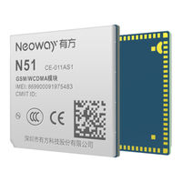
Neoway N51 3G Cellular Module Manuals
Manuals and User Guides for Neoway N51 3G Cellular Module. We have
3
Neoway N51 3G Cellular Module manuals available for free PDF download: Hardware User's Manual, User Manual
Neoway N51 Hardware User's Manual (57 pages)
Brand:
Neoway
| Category:
Control Unit
| Size: 3 MB
Table of Contents
Table of Contents
3
About N51
10
Product Overview
10
Block Diagram
10
Table 1-1 Variant and Frequency Bands
10
Basic Features
11
Figure 1-1 Block Diagram
11
Table 1-2 Basic Features
11
Module Pins
13
Pad Layout
13
Figure 2-1 Pin Assignment of N51
13
Pin Description
14
Table 2-1 IO Definition
14
Table 2-2 Pin Description
14
Application Interfaces
19
Power Interfaces
19
Vbat
19
Figure 3-1 Reference Design 1
20
Figure 3-2 Reference Design 2
20
Figure 3-3 Reference Design 3
21
Vdd_1P8
23
Vddio
23
Control Interfaces
23
Pwrkey_N
23
Figure 3-4 Reference Design of Startup Controlled by Button
23
Figure 3-5 Reference Design of Startup Controlled by MCU
24
Figure 3-6 Reference Design of Automatic Start Once Powered up
24
Reset_N
25
Figure 3-7 N51 Startup Timing
25
Figure 3-8 N51 Shutdown Timing
25
Peripheral Interfaces
26
Usb
26
Figure 3-9 Reset Timing of N51
26
Uart
27
Figure 3-10 USB Connection
27
Figure 3-11 Reference Design 1 of UART Connection
28
Figure 3-12 Reference Design 2 of UART Connection
28
Figure 3-13 Recommended Level Shifting Circuit 1
29
Figure 3-14 Recommended Level Shifting Circuit 2
29
Figure 3-15 Recommended Level Shifting Circuit 3
30
Usim
31
Figure 3-16 Reference Design of USIM Card Interface
31
Spi
32
I2C
33
Figure 3-17 SPI Connection
33
Figure 3-18 I2C Connection
33
Audio Interface
34
Analog Audio Input Interfaces
34
Figure 3-19 Reference Design of Differential MIC Input
34
Analog Audio Output Interfaces
35
Figure 3-20 Reference Design of SPK Differential Output
35
RF Interface
36
Antenna Interface
36
Figure 3-21 L Network
36
Figure 3-22 T Network
37
Figure 3-23 Pi Network
37
Antenna Assembling
38
Figure 3-24 Recommended RF PCB Design
38
Figure 3-25 Specifications of MM9329-2700RA1
38
Figure 3-26 RF Connections
39
Figure 3-27 Antenna Layout
39
GPIO Interface
40
MUX Interfaces
40
Figure 3-28 Layout Around the Antenna
40
Table 3-1 MUX Pins
40
Other Interfaces
41
Ring
42
Figure 3-29 Pulse Wave for an Incoming Call
42
Figure 3-30 RING Indicator for SMS
42
Net_Light
43
Sleep
43
Figure 3-31 Reference Design of LED Driving
43
Figure 3-32 Reference Design of Sleep Control
43
Adc
44
Usb_Boot
44
Keypad
44
Figure 3-33 Reference Design of USB_BOOT
44
Figure 3-34 Reference Design of Keypads
45
Electric Feature and Reliability
46
Electric Features
46
Table 4-1 Operating Conditions of N51
46
Table 4-2 Current Consumption of N51 (Typical)
46
Temperature Feature
47
ESD Protection
47
Table 4-3 Temperature Features of N51
47
Table 4-4 N51 ESD Protection
47
RF Features
48
Operating Bands
48
TX Power and RX Sensitivity
48
Table 5-1 Operating Band of N51
48
Table 5-2 TX Power and RX Sensitivity of N51
48
Mechanical Features
50
Dimensions
50
Figure 6-1 N51 Dimensions (Unit: MM)
50
Three Views
51
Packing
51
Tray
51
Moisture
51
Figure 6-2 Three Views of N51
51
Mounting N51 Onto the Application Board
52
Bottom Dimensions
52
Figure 7-1 N51 Bottom Dimensions (Unit: MM)
52
Application Foot Print
53
Stencil
53
Solder Paste
53
Figure 7-2 Recommended PCB Foot Print (Unit: MM)
53
SMT Furnace Temperature Curve
54
Figure 7-3 SMT Furnace Temperature Curve
54
Safety Recommendations
55
A Abbreviation
56
Advertisement
Neoway N51 User Manual (14 pages)
EVK
Brand:
Neoway
| Category:
Motherboard
| Size: 0 MB
Table of Contents
Table of Contents
3
1 Overview
6
2 About N51 EVB
7
3 Power and Connection
9
Power Supply
9
2A Adapter
9
Soldering Power Cable
9
Communication Connection
10
M5X0-PWR Board
10
Micro-USB Cable
11
4 Commissioning
12
Through Serial Port
12
Through USB Port
13
Neoway N51 User Manual (12 pages)
Brand:
Neoway
| Category:
GSM/GPRS Modules
| Size: 0 MB
Table of Contents
Table of Contents
3
Overview
5
EVB Functions
6
Power Supply and Connection
8
Connecting the EVB to a Power Source
8
Using an AC/DC Power Adapter
8
Using Alligator Clips
8
Soldering Cables
9
Power on the Module
10
Communication Connection
10
Antenna Connection
10
Commissioning
12
Advertisement
Advertisement
Related Products
Neoway N58
Neoway N21-EU-011AS1
Neoway Neo_M680
Neoway N11 V2
Neoway N720
Neoway N27
Neoway N77
Neoway N75-A
Neoway N75-NA
Neoway N75 EVK
Neoway Categories
Control Unit
GSM/GPRS Modules
Motherboard
Network Router
Network Hardware
More Neoway Manuals
Login
Sign In
OR
Sign in with Facebook
Sign in with Google
Upload manual
Upload from disk
Upload from URL