Sign In
Upload
Manuals
Brands
MR Manuals
DC Drives
ETOS TD
MR ETOS TD Manuals
Manuals and User Guides for MR ETOS TD. We have
1
MR ETOS TD manual available for free PDF download: Operating Instructions Manual
MR ETOS TD Operating Instructions Manual (356 pages)
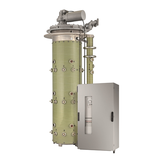
Motor-drive unit
Brand:
MR
| Category:
DC Drives
| Size: 17 MB
Table of Contents
Table of Contents
3
1 Introduction
10
Manufacturer
10
Completeness
10
Safekeeping
10
Notation Conventions
11
Symbols
11
Hazard Communication System
12
Information System
13
Instruction System
14
Typographic Conventions
14
2 Safety
15
Appropriate Use
15
Inappropriate Use
15
Fundamental Safety Instructions
16
Personnel Qualification
18
Personal Protective Equipment
19
Drying Transformer
20
Drying Transformer in Autoclave
20
Drying Transformer in Its Own Tank
20
3 Security
21
4 Product Description
24
Scope of Delivery
24
Function Description
24
Performance Features
25
Operating Modes
26
Design
27
Name Plate
28
Gear Motor
28
Control Cabinet
29
ISM® Assemblies
31
Visualization
38
Main Screen
38
Additional Operating Controls and Display Elements When Using the Mcontrol Touch Panel (Optional)
42
Operating Concept
42
5 Packaging, Transport and Storage
46
Packaging
46
Suitability
46
Markings
47
Transportation, Receipt and Handling of Shipments
47
Storage of Shipments
48
Unpacking Shipments and Checking for Transportation Damages
49
6 Mounting
52
Fitting the Control Cabinet to the Transformer
52
Cable Recommendation
55
Information about Connecting Serial Interfaces RS232 and RS485
55
Notes on Connecting to the MR Sensor Bus
57
Msense® Dga
59
MESSKO® Mtec® EPT303 FO
60
Messko® Mtrab® 2.5
61
Msense®-Fo Ecu-I/S
62
Information about Connecting Analog Sensors
62
Information about Screening the Cables for Analog Signals
65
Information about Laying Fiber-Optic Cable
65
Connecting Motor-Drive Unit
66
7 Commissioning
69
Performing Tests
69
Function Test of the Motor-Drive Unit
69
High-Voltage Tests on the Transformer
69
Dielectric Tests on Transformer Wiring
70
Transporting Transformer to the Operating Site
70
Commissioning the Transformer at the Operating Site
71
8 Operation
72
Actuating Motor-Drive Unit Locally
72
Selecting the Operating Mode
72
Monitoring Motor-Drive Unit
72
9 Visualization
73
Establishing Connection to Visualization
73
General
75
Setting General Device Functions
76
Set up Automatic Logout
77
Activating/Deactivating Service User Access
78
Configuring the Network
79
Mqtt
81
Setting the Device Time
83
Time Synchronization Via PTP
84
Configuring Syslog
85
Scada
87
Configuring IEC 61850 (Optional)
87
Configuring IEC 60870-5-101 (Optional)
89
Configuring IEC 60870-5-103 (Optional)
92
Configuring IEC 60870-5-104 (Optional)
94
Configuring Modbus (Optional)
96
Configuring DNP3 (Optional)
98
Configuring GOOSE (Optional)
100
Configure Data Points (Optional)
105
Display Status of the SCADA Connection
112
Name Plate
113
Enter the Name Plate Data
113
Displaying the Name Plate
114
Linking Signals and Events
114
Linking Functions
115
Linking Digital Outputs
117
Linking Control System Messages
118
Cooling System Control (Optional)
119
Configuring Cooling Stages
119
Set the Operating Mode
121
Deactivating Cooling System Control
121
Configuring Load-Dependent Mode
121
Configuring Periodic Mode
123
Configuring Alternating Mode
124
Configuring the Frequency-Based Cooling System Control
125
Displaying Status of Cooling Stages
128
Cooling System Monitoring (Optional)
129
Setting the Cooling System Monitoring Function
129
Cooling Efficiency Monitoring (Optional)
130
Cooling System Flow Monitoring (Optional)
131
Drive Overview
135
Displaying Power Characteristics
136
Regulation
137
Response to Control System Disconnection (Optional)
137
Setting Control Variable (Optional)
139
Voltage Regulation
140
Setting the Desired Value
140
Reactive Power Regulation (Optional)
157
Transformer Data
160
Setting Transformer Data
161
Circuit Examples for Voltage Transformers and Current Transformers
163
Measurement
176
UI Measuring Channels
176
Control Variable
177
Regulation Mode
177
Display Power Factor Negative
177
Synchronizing the Motor-Drive Unit
178
Single-Column On-Load Tap-Changer Model
178
Multi-Column On-Load Tap-Changer Model
179
Line Drop Compensation
180
R&X Compensation
180
Z Compensation
180
Parallel Operation (Optional)
183
Parallel Operation Methods
184
Configuring Parallel Operation
188
TAPCON® 2Xx Retrofit
192
Detecting Parallel Operation Via Group Inputs (Optional)
193
Monitoring Functions
194
Voltage Monitoring
194
Current Monitoring
196
Power Monitoring
199
Power Flow Monitoring
201
Tap Position Monitoring (Optional)
203
U Bandwidth Monitoring
204
Q Bandwidth Monitoring (Optional)
206
Phase Symmetry Monitoring
208
Temperature Monitoring
209
Monitoring the Gas Volume of the Buchholz Relay (OLTC)
210
Monitoring the Gas Volume of the Buchholz Relay (Transformer)
211
Monitoring the Oil Pressure (Transformer)
211
Monitoring the Oil Pressure (On-Load Tap-Changer)
212
Target-Tap-Position Operation
213
Measured Values
213
Displaying Current Measured Values
213
Displaying Measured Value Recorder (Optional)
214
Setting the Measured Value Recorder
218
Displaying Temperature Curve (Optional)
220
Displaying Winding Temperatures (Optional)
221
Displaying the Measured Values of the Buchholz Relay (Optional)
221
Displaying the Measured Values of the Pressure Relief Device (Optional)
222
Displaying the Measured Value Trend of the Oil Level and Dehydrating Breather (Optional)
222
On-Load Tap-Changer Monitoring
223
Changing Tap Position Designation (Optional)
223
Setting the TCR Calculation Factor (Optional)
223
Displaying Tap-Change Operation Statistics (Optional)
224
Motor Current Index (MCI)
225
Displaying Information about Contact Wear (Only OILTAP®)
229
Configuring OLTC Precheck
230
Information about the On-Load Tap-Changer
231
Transformer Monitoring (Optional)
232
Hot-Spot Calculation (Optional)
232
Hot-Spot Forecast (Optional)
235
Setting Calculation of Transformer's Loss of Life (Optional)
236
Displaying Protective Device Status (Optional)
237
Dissolved Gas Analysis (Optional)
237
Configuring DGA Monitoring
238
Displaying Measured Values
241
MR Sensor Bus
246
Configuring MR Sensor Bus
247
Managing Sensors
248
Function Assignment
250
Defining the Sensors
251
Displaying Information on the Connected Sensors
255
Configuring Analog Inputs and Outputs (Optional)
257
Configuring Digital Inputs and Outputs
259
Maintenance (Optional)
261
Setting Operator Interval for OLTC Maintenance
262
Setting Operator Interval for Transformer Maintenance
263
Undertaking and Confirming Maintenance
264
Displaying Maintenance Overview
267
Displaying the Maintenance Logbook
267
Suppressing a Maintenance Event
269
Dynamic Transformer Rating (Optional)
270
Configuring the Dynamic Transformer Rating
271
Displaying the Dynamic Transformer Rating
272
Event Management
274
Displaying and Acknowledging Events
274
Configuring Events
275
Displaying Event Memory
277
User Administration
278
User Roles
278
Changing the Password
280
Creating, Editing and Deleting Users
281
Setting Access Rights to Parameters and Events
282
User Authentication Via RADIUS (Optional)
283
Information about Device
285
Hardware
285
Software
286
Parallel Operation
286
Import/Export Manager
287
Exporting Data
287
Importing Data (Software Version 3.44 and Later)
288
Configuring Media Converter with Managed Switch
289
Commissioning
290
Configuration
291
TAPCON® Personal Logic Editor (TPLE)
292
Function
292
Configuring TPLE
306
10 Fault Elimination
310
Motor-Drive Unit
310
Human-Machine Interface
311
Other Faults
311
11 Inspection and Maintenance
312
Maintaining Motor-Drive Unit
312
Cleaning Motor-Drive Unit
312
12 Event Messages
313
13 Disassembly
324
14 Disposal
326
15 Technical Data
327
Gear Motor
327
Control Cabinet
327
Connection Terminals
328
Drawings
329
ISM® Assemblies
335
Voltage Measurement and Current Measurement
335
UI 5-4 Voltage Measurement and Current Measurement
336
Digital Inputs and Outputs
338
Analog Inputs and Outputs
340
CPU (Central Processing Unit) I
341
CPU (Central Processing Unit) II
343
System Networking
345
Tests
347
Glossary
348
List of Key Words
350
Advertisement
Advertisement
Related Products
MR ETOS ED
MR ETOS IM
MR ECOTAP VPD III
MR ECOTAP VPD CONTROL PRO
MR TAPMOTION ED 100-S/L
MR TAPMOTION ED 200-S/L
MR MESSKO EI100/160
MR CEDASPE DAROC EDS R2
MR CEDASPE DAROC EDS-R 50
MR CEDASPE DAROC EDS-R 80
MR Categories
Industrial Equipment
Controller
Measuring Instruments
Thermometer
Control Systems
More MR Manuals
Login
Sign In
OR
Sign in with Facebook
Sign in with Google
Upload manual
Upload from disk
Upload from URL