Sign In
Upload
Manuals
Brands
MR Manuals
Measuring Instruments
ETOS IM
MR ETOS IM Manuals
Manuals and User Guides for MR ETOS IM. We have
1
MR ETOS IM manual available for free PDF download: Operating Instructions Manual
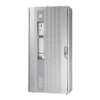
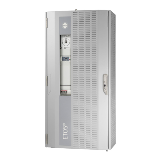
MR ETOS IM Operating Instructions Manual (412 pages)
Brand:
MR
| Category:
Measuring Instruments
| Size: 20 MB
Table of Contents
Table of Contents
3
1 Introduction
11
Manufacturer
11
Completeness
11
Safekeeping
11
Notation Conventions
11
Hazard Communication System
11
Information System
13
Instruction System
13
Typographic Conventions
14
2 Safety
15
Appropriate Use
15
Inappropriate Use
16
Fundamental Safety Instructions
16
Personnel Qualification
18
Personal Protective Equipment
19
3 IT Security
21
4 Product Description
25
Scope of Delivery
25
Function Description
26
Bushing Monitoring
26
Performance Features
27
Design
29
Power Supply
30
CPU (Central Processing Unit) I
31
Voltage Measurement and Current Measurement
32
Digital Inputs and Outputs
33
Analog Inputs and Outputs
33
Media Converter
34
Media Converter with Managed Switch
35
Voltage Measurement
36
Bus Extension Module
36
Bushing Adapter and Bushing Coupling Unit
37
Main Screen
38
Additional Operating Controls and Display Elements When Using the Mcontrol Touch Panel (Optional)
41
Operating Concept
41
5 Mounting
47
Preparation
47
Electromagnetic Compatibility
47
Wiring Requirement of Installation Site
48
Wiring Requirement of Operating Site
48
Wiring Requirement in Control Cabinet
49
Information about Shielding the CAN Bus
50
Minimum Distances
51
Installing the 19-Inch Plug-In Housing
51
Installing the Individual Components on a Cap Rail
54
Fastening the Cap Rail
54
Installing the Bus Rail on the Cap Rail
55
Installing the Assembly at a Distance on the Cap Rail
56
Connecting Device
57
Cable Recommendation
58
Information about Connecting Serial Interfaces RS232 and RS485
59
Notes on Connecting to the MR Sensor Bus
61
Information about Laying Fiber-Optic Cable
63
Mounting Terminating Resistor of CAN Bus
64
Connecting Cables to the System Periphery
64
Wiring the CPU Assembly
65
Wiring the UI 1/UI 3/UI 5 Assembly
68
Wiring the AIO 2/AIO 4/AIO 8 Assembly
69
Wiring the DIO Assembly
74
Wiring the MC 2-2/SW3-3 Assembly
78
Wiring the QS3.241 Assembly
81
Connecting the Power Supply
83
6 Commissioning
85
Performing Tests
85
Ground Test
85
Performing a Dielectric Test
87
Setting the Language
89
Setting Date and Time
90
Commissioning Wizard
90
Checking Measured Values and Status of Digital Inputs and Outputs
91
7 Operation
92
Establishing Connection to Visualization
92
General
94
Configuring Visualization
94
Activating/Deactivating Automatic Launch of Commissioning Wizard
95
Setting Measured Value Display
95
Transformer Name
96
Remote Behavior
96
Accessing Online Help
96
Activating/Deactivating the USB Interface
96
Set up Automatic Logout
97
Control (Optional)
97
Setting the Desired Value
98
Bandwidth
111
Delay Time T1
112
Delay Time T2
114
Transformer Data
116
Setting Transformer Data
116
Circuit Examples for Voltage Transformers and Current Transformers
119
Measurement
133
Setting UI Measuring Channels
133
Control Variable
133
Regulation Mode
134
Setting the Display for the Power Factor
134
Control of the Motor-Drive Unit (Optional)
135
Setting the Switching Pulse for Controlling the Motor-Drive Unit
135
Setting Motor Runtime Monitoring
136
Setting the Switching Direction
137
Parallel Operation (Optional)
137
Parallel Operation Methods
137
Configuring Parallel Operation
142
TAPCON® 2Xx Retrofit
147
Detecting Parallel Operation Via Group Inputs (Optional)
148
Monitoring Functions
149
Voltage Monitoring
149
Current Monitoring
151
Power Monitoring
154
Power Flow Monitoring
155
Tap Position Monitoring (Optional)
157
Bandwidth Monitoring
158
Phase Symmetry Monitoring
160
Temperature Monitoring
162
Tx Statistics Monitoring
163
Monitoring the Gas Volume of the Buchholz Relay (OLTC)
164
Monitoring the Gas Volume of the Buchholz Relay (Transformer)
165
Monitoring the Oil Pressure (Transformer)
166
Monitoring the Oil Pressure (On-Load Tap-Changer)
167
Target-Tap-Position Operation
168
Measured Values
168
Displaying Current Measured Values
168
Displaying Measured Value Recorder (Optional)
169
Setting the Average Value Interval
173
Displaying Temperature Curve (Optional)
174
Displaying Winding Temperatures (Optional)
175
Displaying the Measured Values of the Buchholz Relay (Optional)
176
Displaying the Measured Values of the Pressure Relief Device (Optional)
177
Displaying the Measured Values of the Dehydrating Breather (Optional)
177
On-Load Tap-Changer Monitoring
178
Changing Tap Position Designation (Optional)
178
Displaying Tap-Change Operation Statistics (Optional)
179
Motor Current Index (MCI)
180
Displaying Information about Contact Wear (Only OILTAP®)
184
Transformer Monitoring
185
Hot-Spot Calculation (Optional)
185
Hot-Spot Forecast (Optional)
188
Setting Calculation of Transformer's Loss of Life (Optional)
189
Displaying Protective Device Status (Optional)
190
Cooling System Control (Optional)
191
Configuring Cooling Stages
191
Configuring Load-Dependent Mode
195
Configuring Periodic Mode
196
Configuring Alternating Mode
196
Displaying Status of Cooling Stages
197
Configuring the Frequency-Based Cooling System Control
198
Dissolved Gas Analysis (Optional)
201
Configuring DGA Monitoring
202
Displaying Measured Values
205
Bushing Monitoring (Optional)
211
Setting the Transformer Data for the Reference System (Optional)
211
Configuring Bushing Monitoring
212
Displaying the State of the Bushings
218
MR Sensor Bus
219
Configuring MR Sensor Bus
219
Managing Sensors
222
Function Assignment
223
Defining the Sensors
224
Displaying Information on the Connected Sensors
229
Configuring Analog Inputs and Outputs (Optional)
230
Configuring Digital Inputs and Outputs
232
Name Plate (Optional)
234
Enter the Name Plate Data
234
Displaying the Name Plate
235
Maintenance (Optional)
235
Setting Operator Interval for OLTC Maintenance
236
Setting Operator Interval for Transformer Maintenance
237
Undertaking and Confirming Maintenance
238
Displaying Maintenance Overview
241
Displaying the Maintenance Logbook
241
Suppressing a Maintenance Event
243
Overload (Optional)
244
Configuring Overload
245
Displaying Overload
251
Event Management
252
Displaying and Acknowledging Events
253
Configuring Events
253
Displaying Event Memory
255
Scada
256
Configuring IEC 61850 (Optional)
256
Configuring IEC 60870-5-101 (Optional)
259
Configuring IEC 60870-5-103 (Optional)
264
Configuring IEC 60870-5-104 (Optional)
267
Configuring Modbus (Optional)
270
Configuring DNP3 (Optional)
273
Configuring GOOSE (Optional)
277
Configure Data Points (Optional)
283
Configuring Syslog
290
Time Synchronization
292
Activating Time Synchronization Using SNTP
293
Entering the Time Server Address
293
Setting the Time Zone
294
Setting Synchronization Interval
294
Automatic Switchover between Daylight Saving Time and Standard Time
295
Setting the Date and Time Manually
295
User Administration
295
User Roles
295
Changing Password
297
Creating, Editing and Deleting Users
298
Setting Access Rights to Parameters and Events
300
User Authentication Via RADIUS (Optional)
301
Information about Device
303
Hardware
303
Software
305
Parallel Operation
305
Import/Export Manager
306
Exporting Data
306
Importing Data (Software Version 3.44 and Later)
308
Configuring Media Converter with Managed Switch
309
Commissioning
309
Configuration
311
Linking Signals and Events
312
Linking Functions
312
Linking Digital Outputs and Control System Messages
314
TAPCON® Personal Logic Editor (TPLE)
316
Function
316
Configuring TPLE
329
8 Fault Elimination
333
General Faults
333
Human-Machine Interface
333
Other Faults
334
9 Messages
335
Event Messages
335
10 Uninstallation
370
Uninstalling the CPU Assembly
371
Uninstalling the UI 1/UI 3 Assembly
374
Uninstalling the AIO 2/AIO 4 Assembly
375
Uninstalling the DIO 28-15/DIO 42-20 Assembly
377
Uninstalling the MC 2-2/SW 3-3 Assembly
379
Uninstalling the QS3.241 Assembly
381
Uninstalling the Bus Rail
382
Removing the Bushing Adapter and Bushing Coupling Unit
383
11 Disposal
384
12 Technical Data
385
Voltage Supply
385
Voltage Measurement and Current Measurement
386
Voltage Measurement UI 5-3
387
Digital Inputs and Outputs
388
Analog Inputs and Outputs
390
CPU (Central Processing Unit) I
391
System Networking
393
Bus Extension Module
394
Bushing Monitoring
395
Bushing Adapter
395
Bushing Coupling Unit
398
Connection Cable
399
Ambient Conditions
399
Standards and Directives
400
13 Appendix
402
Check List for Commissioning
402
Measured Value Log
403
Glossary
404
List of Key Words
406
Advertisement
Advertisement
Related Products
MR MESSKO EI100
MR MESSKO EI100/160
MR MESSKO EI160
MR ETOS ED
MR ETOS TD
MR ECOTAP VPD I
MR CEDASPE DAROC EDS-R 100
MR ECOTRAC SMART BREATHER
MR ECOTAP VPD MD&C
MR CEDASPE DAROC EDS-R 80-8
MR Categories
Industrial Equipment
Controller
Measuring Instruments
Thermometer
Control Systems
More MR Manuals
Login
Sign In
OR
Sign in with Facebook
Sign in with Google
Upload manual
Upload from disk
Upload from URL